Gondola PlottyBot
Introduction
This is Gondola PlottyBot, a vertical pen plotter you can build.
It’s based on a Raspberry Pi Zero W which means it’s loaded with software to make it easy to use. It also comes with novel features. It shares a software stack with the Tabletop PlottyBot.
Features
- Simple control from a web interface, with plot preview, play, pause & stop
- Works on complex days long plots without missing a step
- Arbitrary size, it can be deployed on vertical surfaces of various sizes
- GCode support, or simpler human readable (and kid friendly) Plotter code. Automatic conversion from GCode to Plotter code.
- Various pen stroke aggregation algorithms & normalization to drawing area.
- Internet enabled live drawing
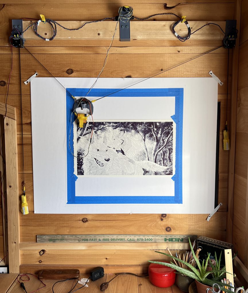
Finished Build
Downloads
Circuit Diagram (optional: for reference)
SKP Model (optional: for editing)
Build Instructions
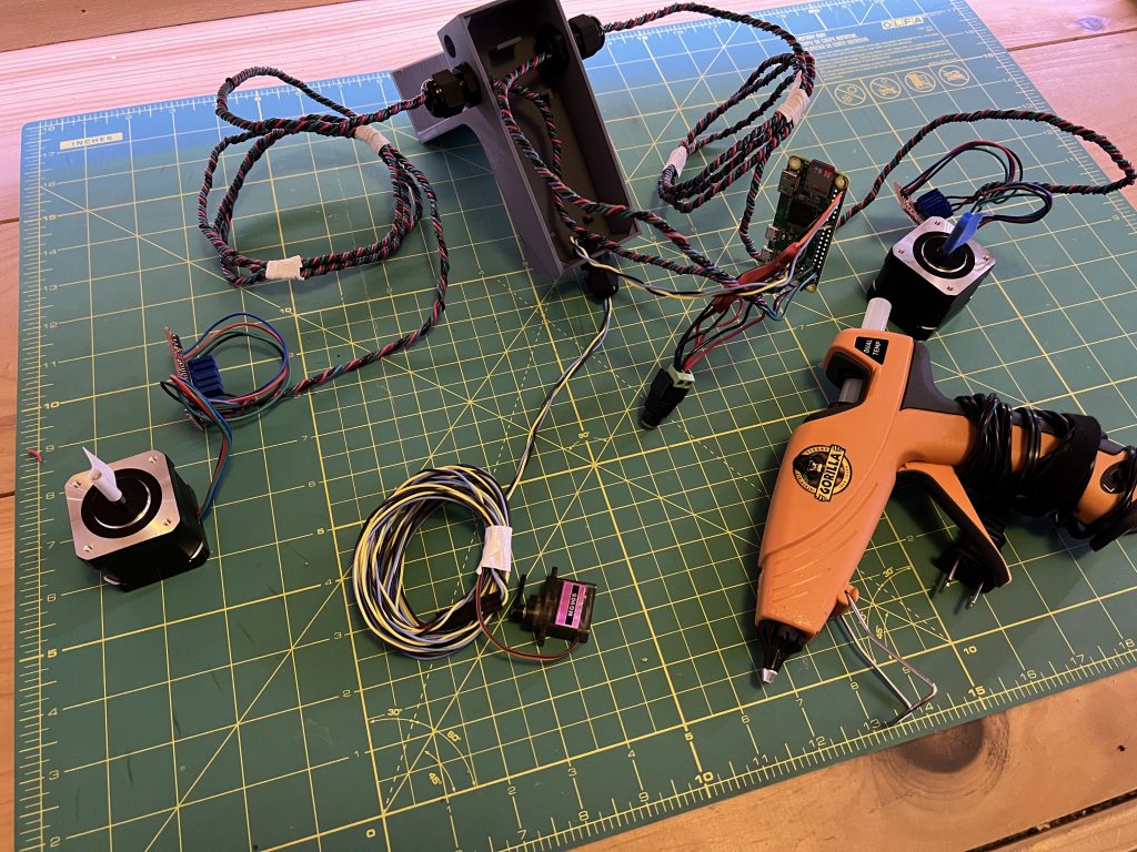
Parts to gather
3D Printed
Grab all the STL parts from here. Each part file has a name finishing with the quantity you need print of it.
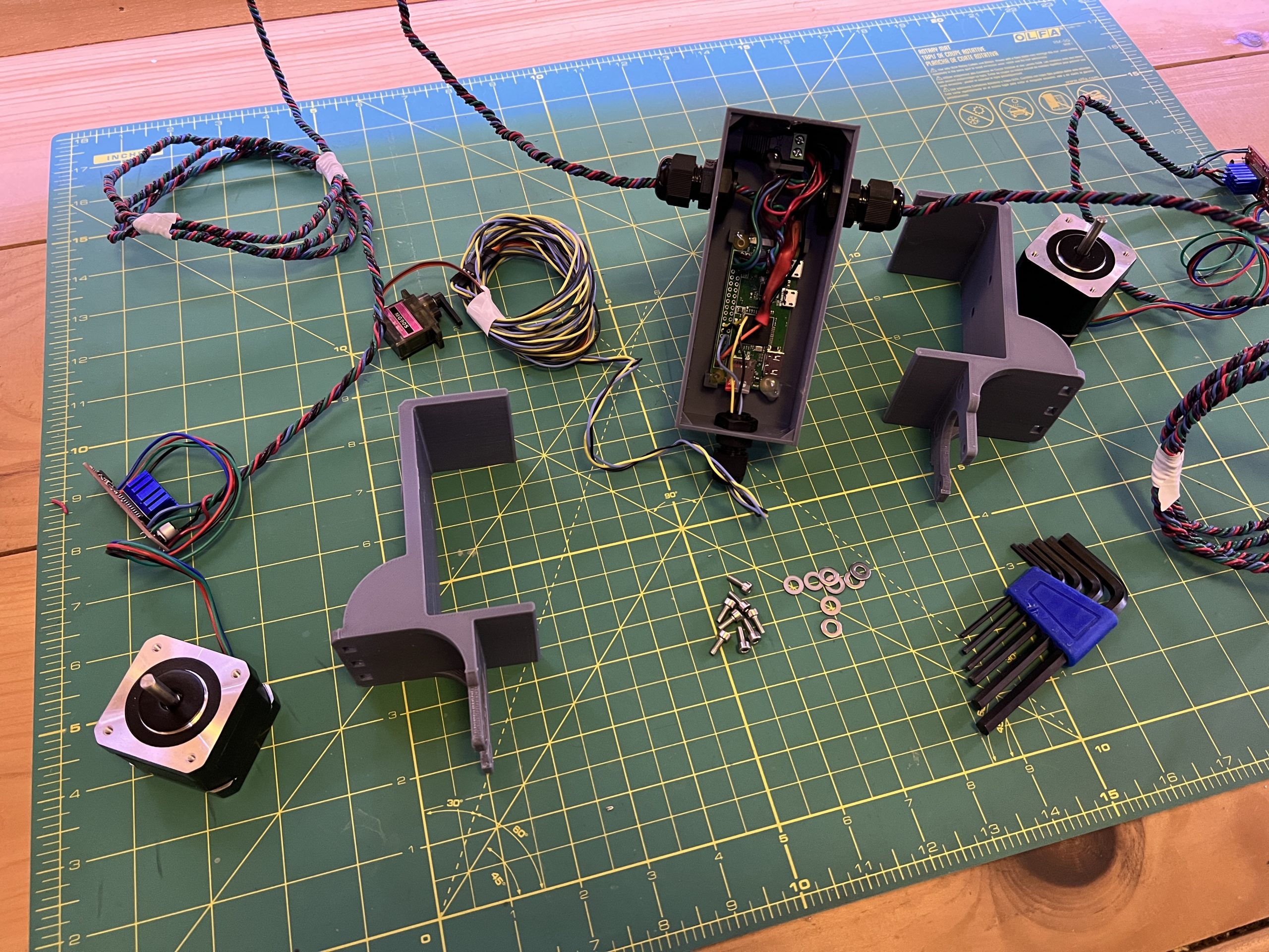
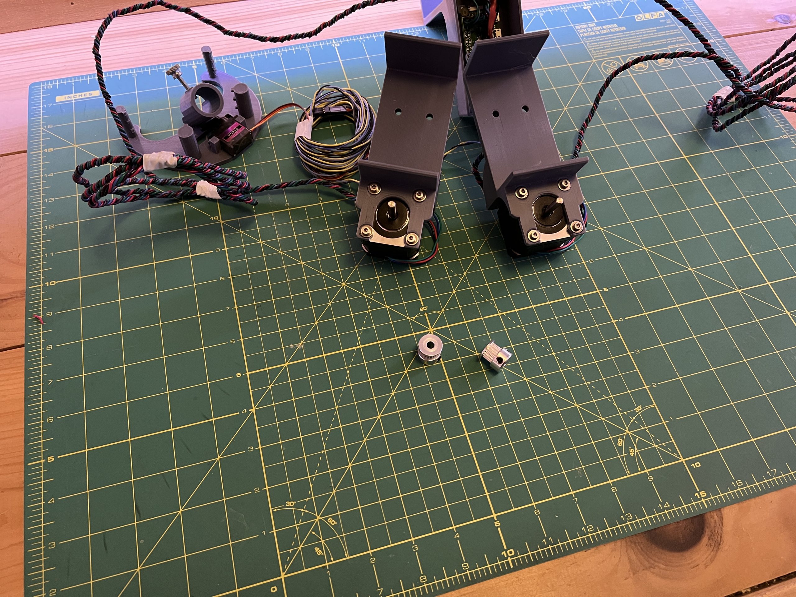
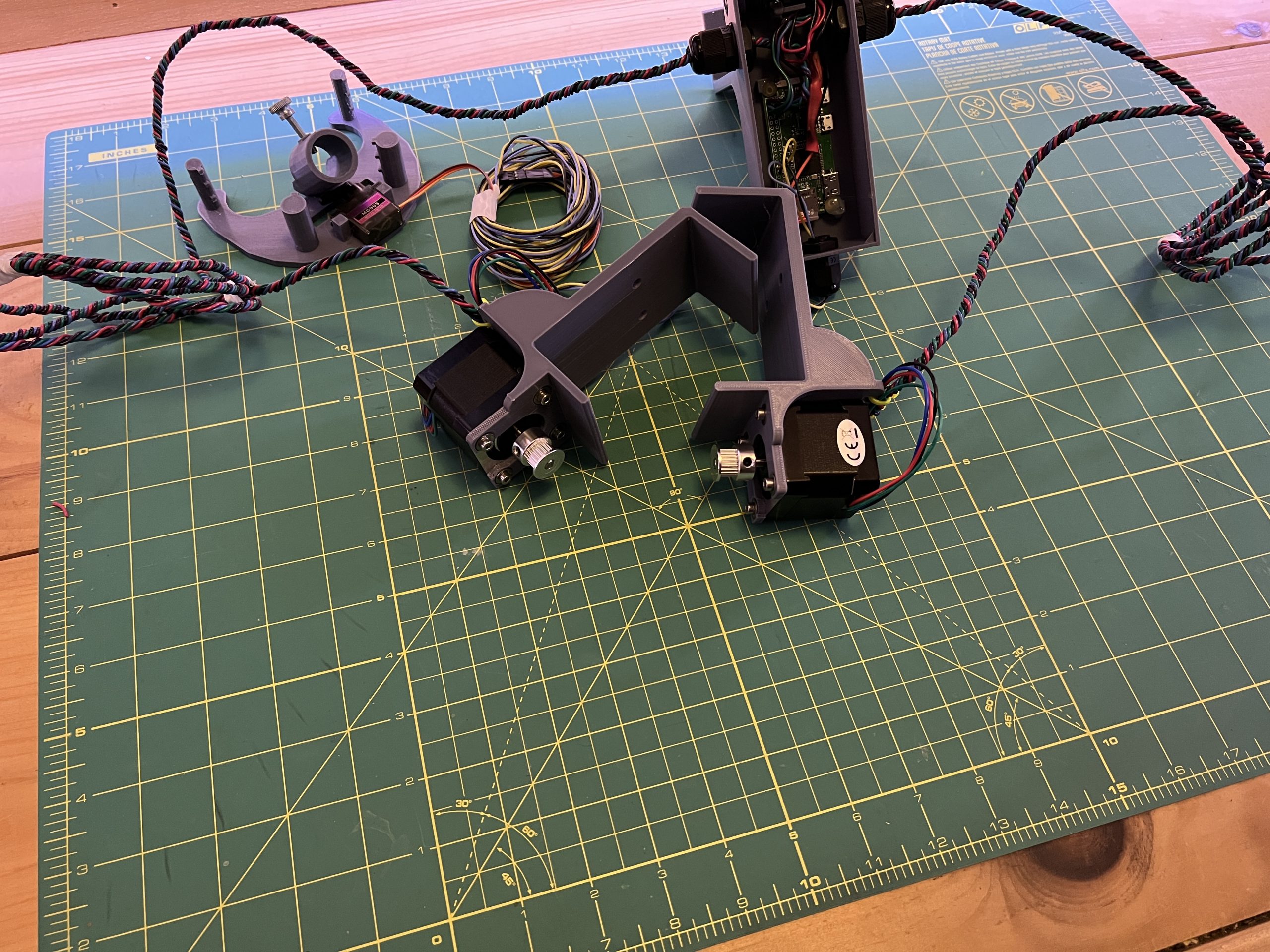
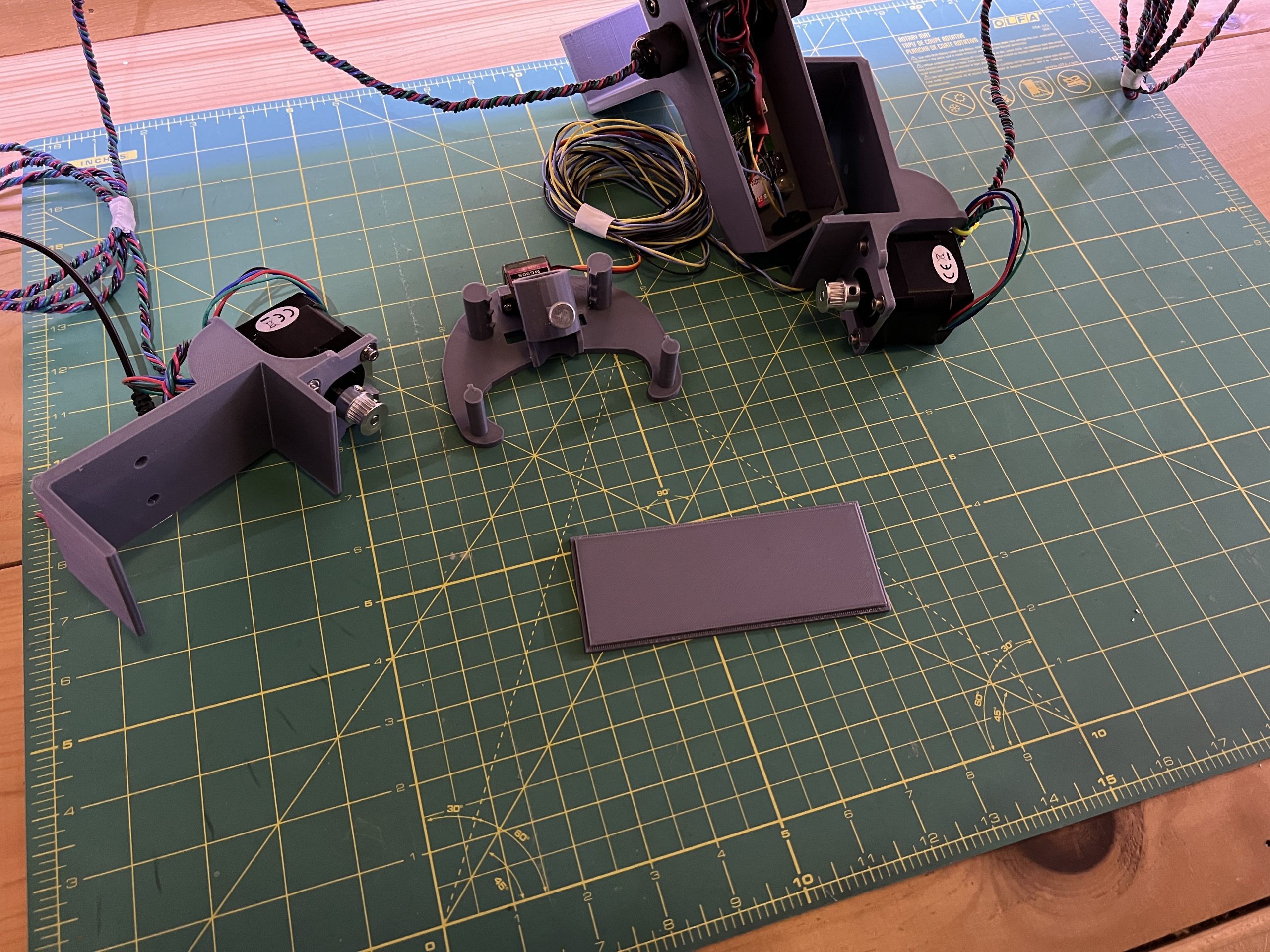
When all are printed, you’ll have this:

Acquired
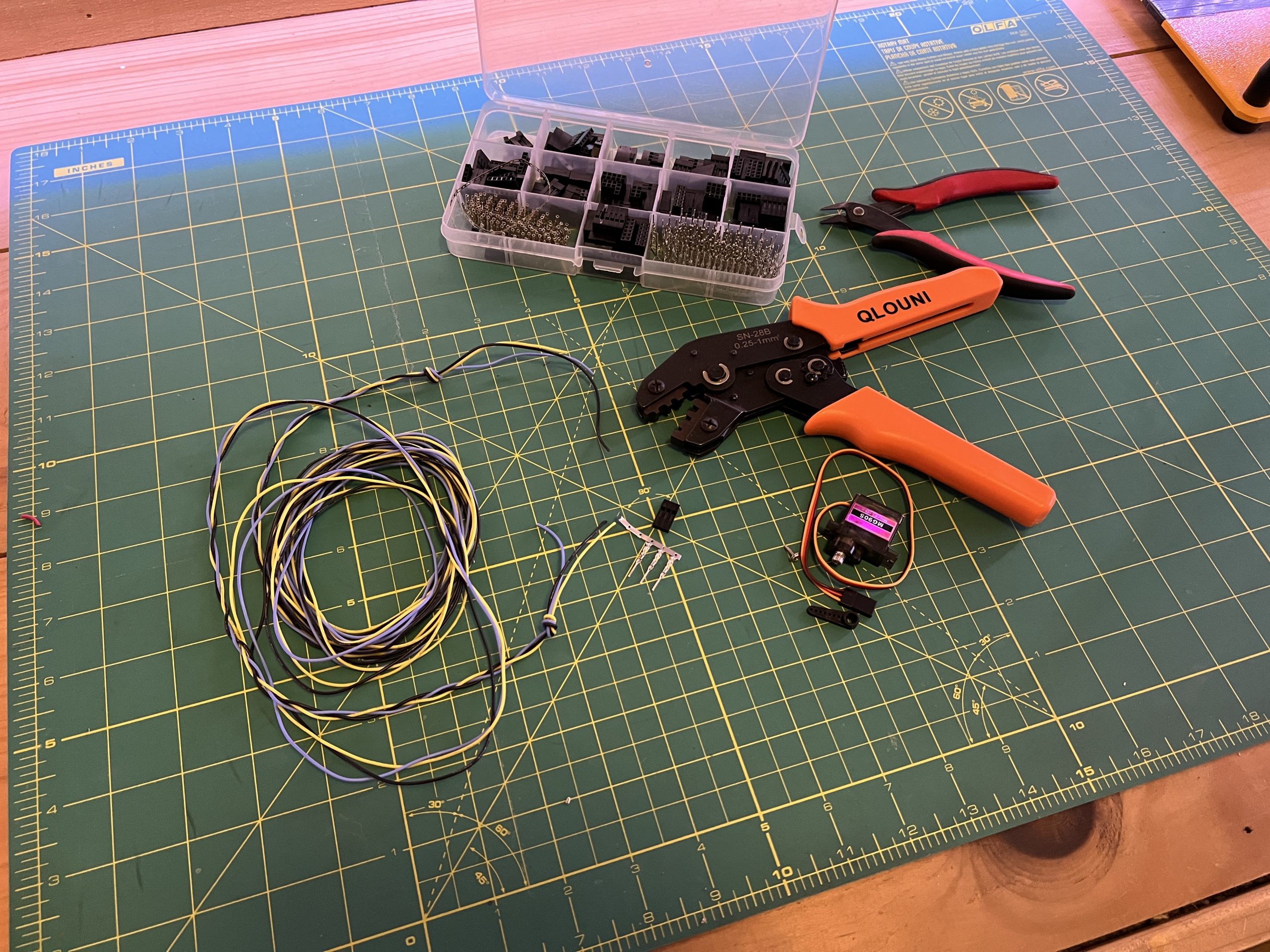
Tools to have
- soldering iron
- glue gun (or sugru moldable glue)
- allen wrench set
- needle nose pliers
- dupont wire connection kit (possibly optional)
- voltmeter (preferable)
- cordless drill (preferable)
Consumables
- 22AWG wiring of various colors
- heat shrink tubing
Circuit
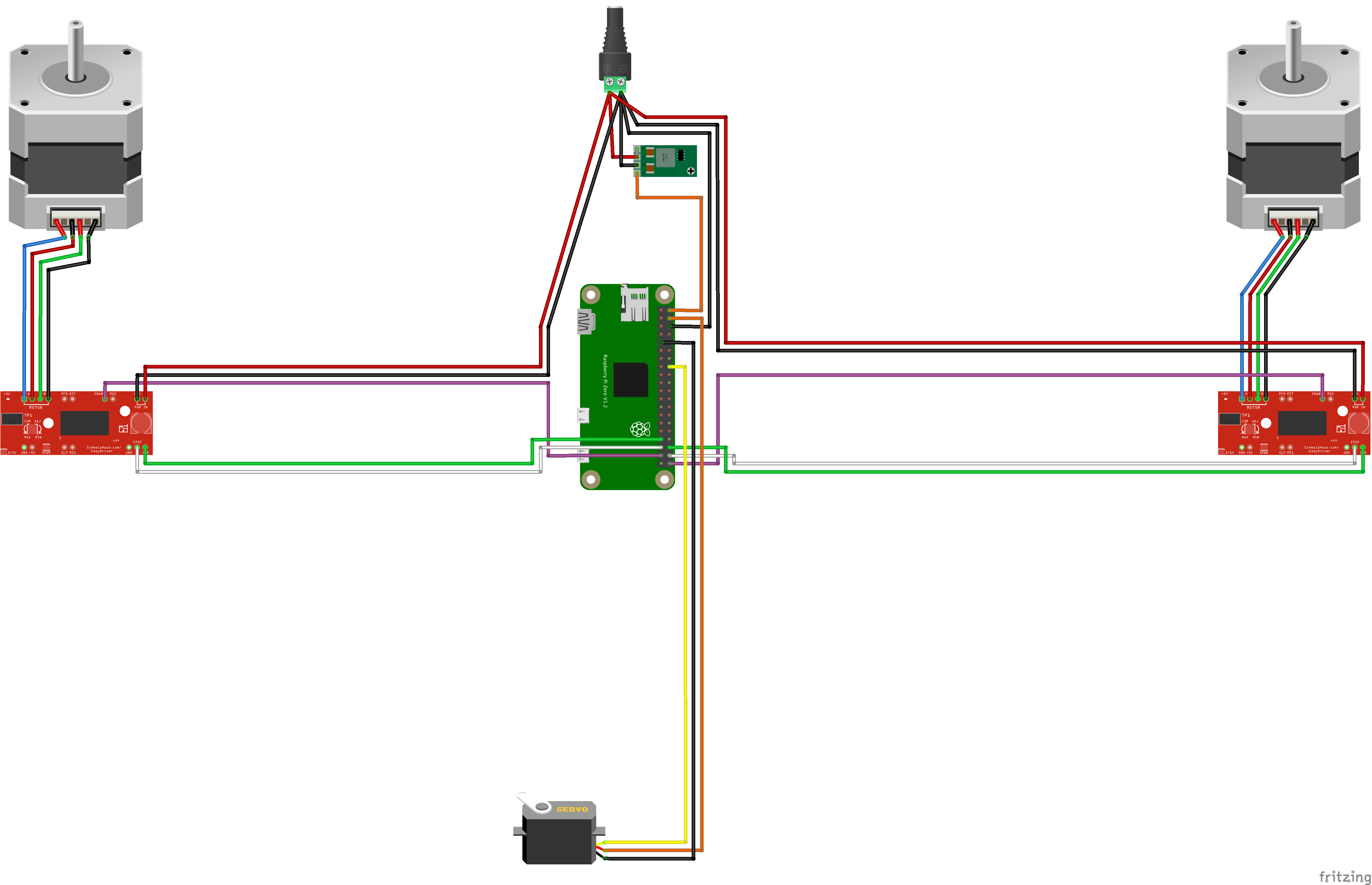
Here is a full representation of the final circuit where we’re going to build. We’ll take it step by step, this is only for reference
(click image for full size)
Step by Step
1. Logic Box
Parts
3D printed
– logic_box_x1
Acquired
– PG9 cable gland x2
– PG7 cable gland x1
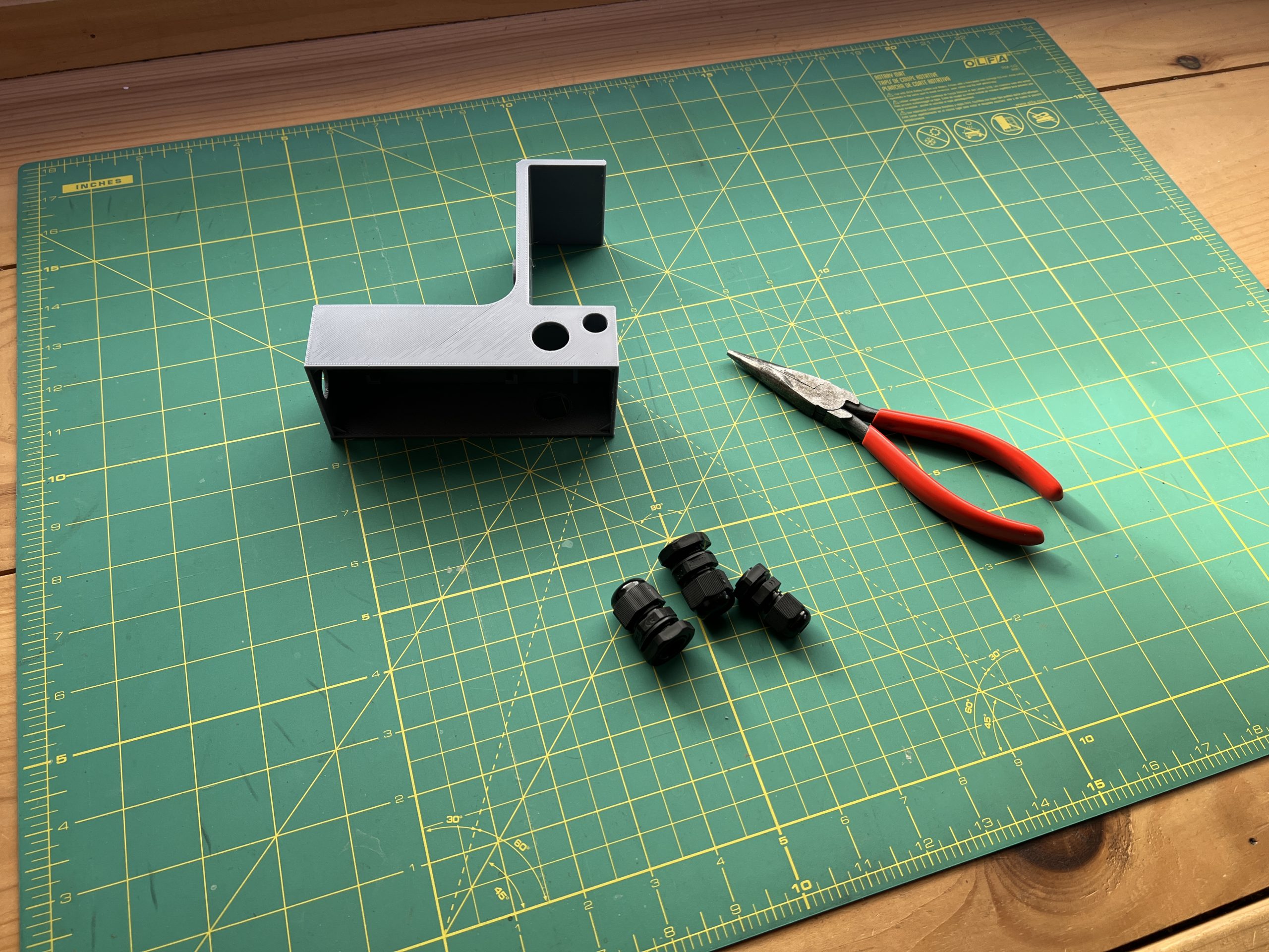
Install the cable glands on the logic box, 2 PG9s on each side and the PG7 in the back. Tighten with help from the pliers.

2. Voltage Regulator & Powering the Pi
Parts
Acquired
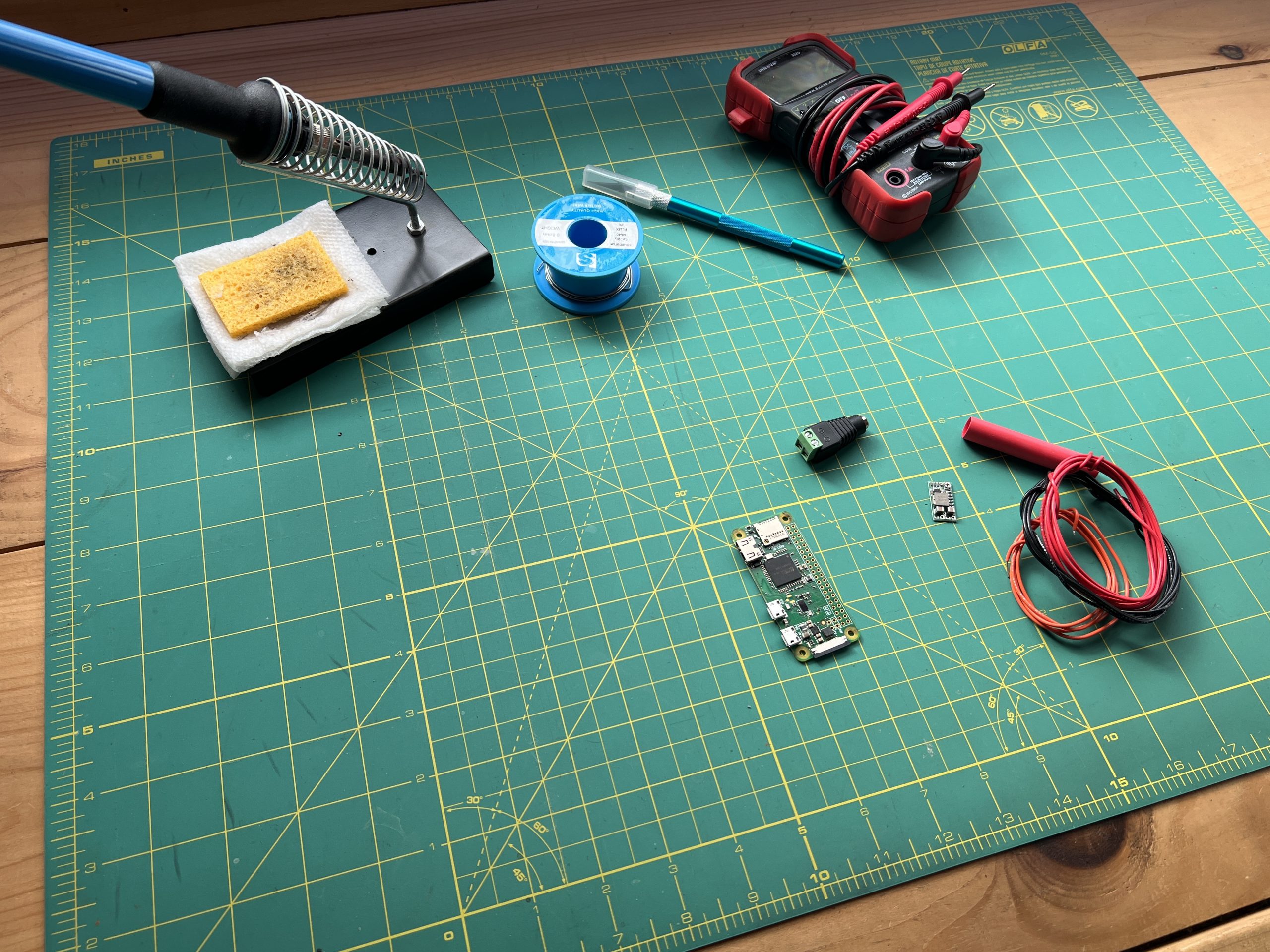
– Raspberry Pi Zero W
– 5V voltage regulator
– black, red & orange electrical wiring
– 12V power connector
– a piece of heat shrink tubing slightly longer than the 5V voltage regulator
The 5V voltage regulator needs to be permanently set to take the 12V from our power supply and convert it into 5V for the Pi. This is done by sectioning one part of the circuit and soldering another.
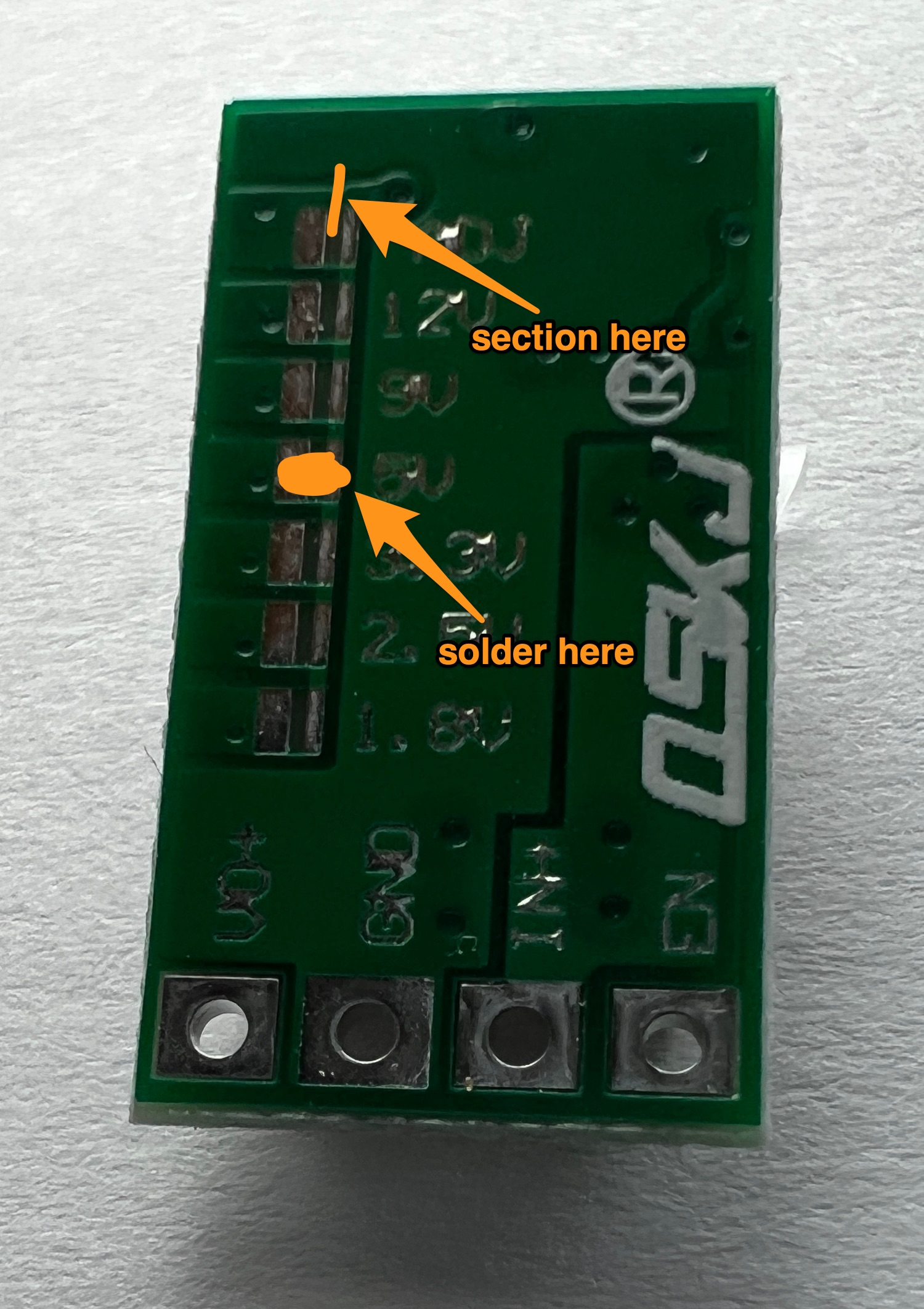
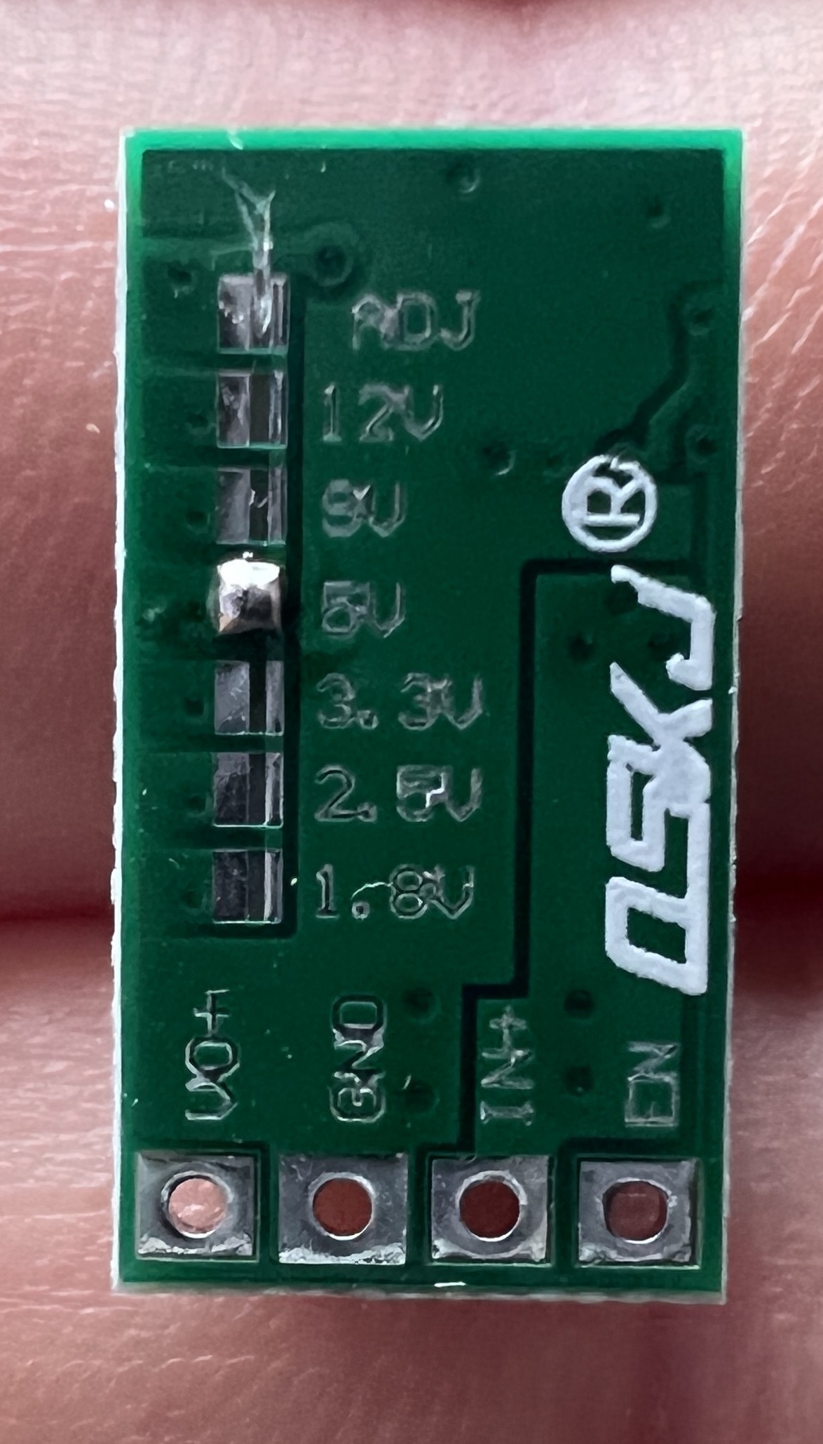
You can use an exacto knife to section the circuit. Make sure you do several passes at different angles, you want to permanently remove any contact. When you are done, your regulator will look something like this:
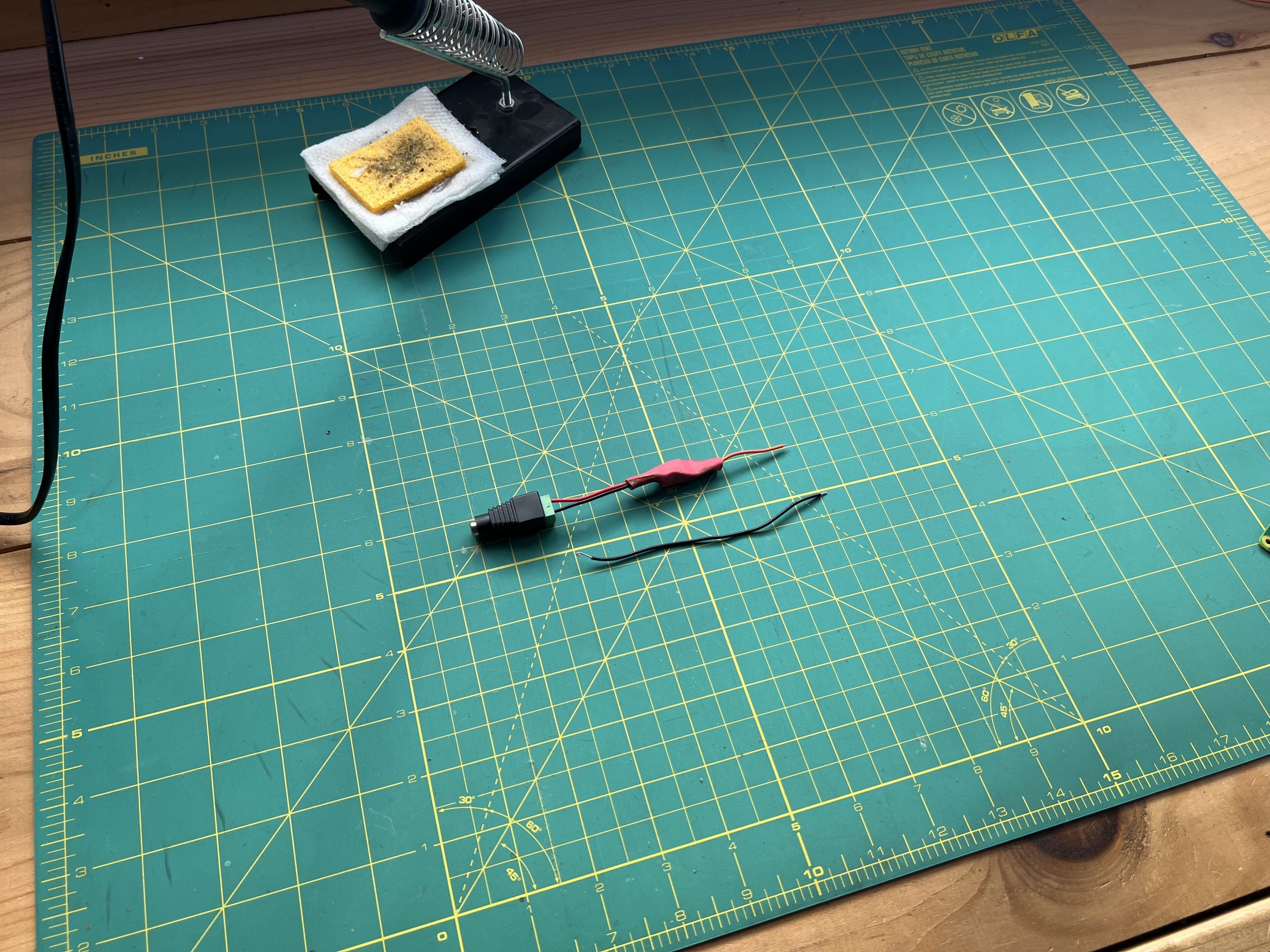
Grab 3 wires of each color, cut them to about 10cm and strip their ends. Then solder them onto the voltage regulator as such:
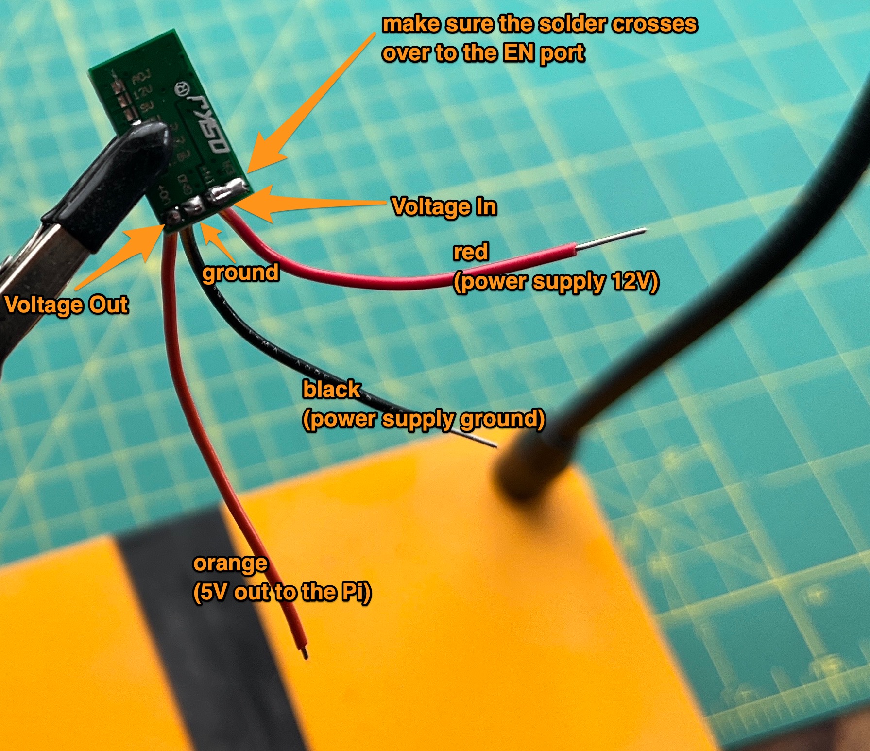
Make sure that the solder crosses from the IN+ port to the EN port. This will make the voltage regulator always ENabled when the plotter is plugged in and receiving 12V.
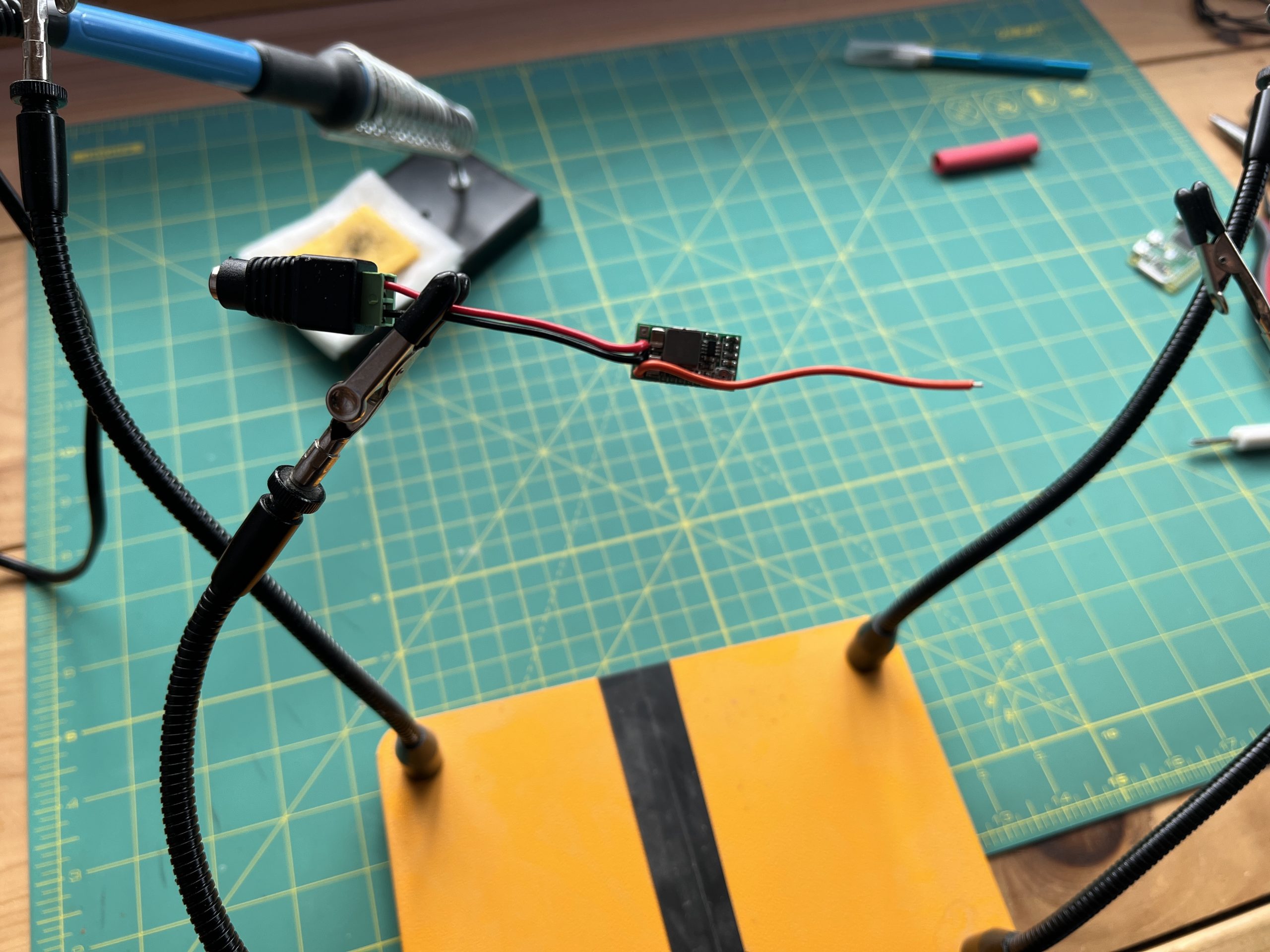
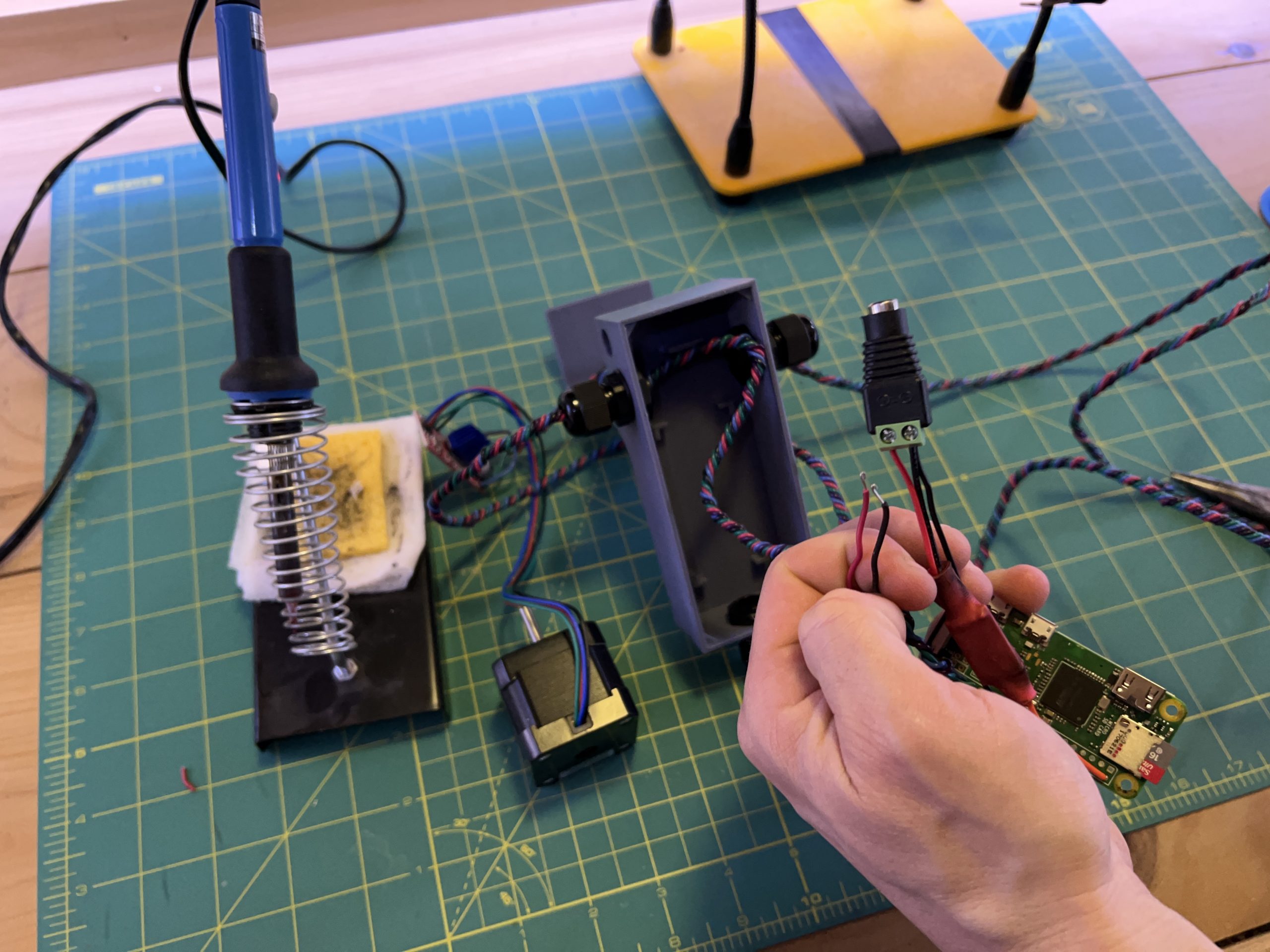
Attach the power connector to the red and black wire you just soldered. Of course red goes to the + side of the connector, and black to the – side.
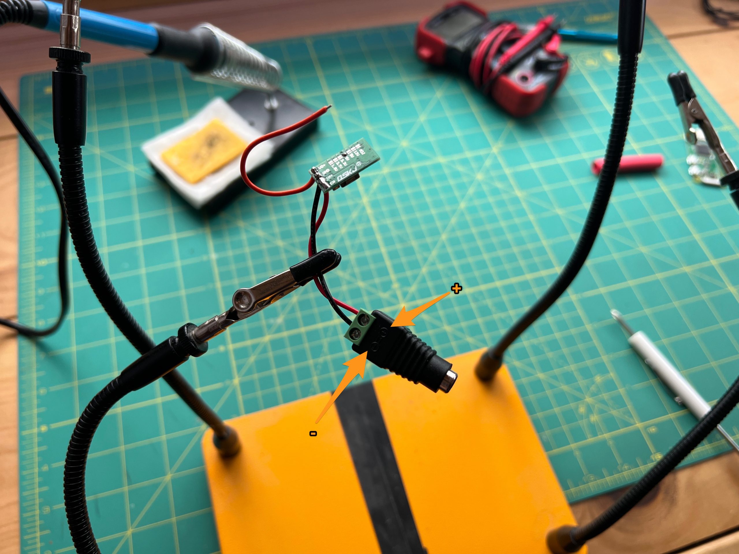
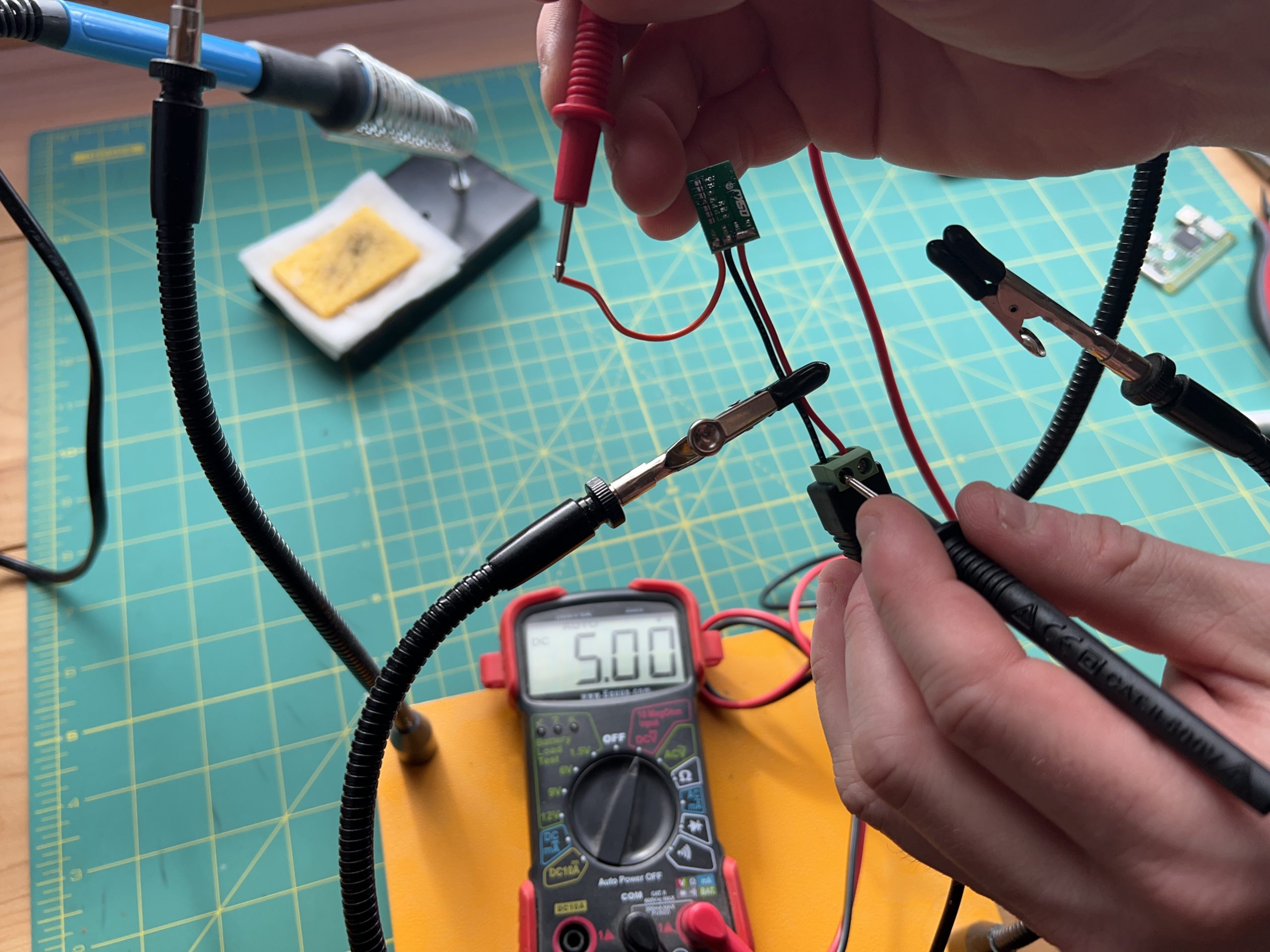
Let verify that the regulator is turning 12V into 5V. Plug in the 12V power supply into the connector.

Grab a voltmeter and measure between – or GND, and the end of the orange wire, you should read 5V.
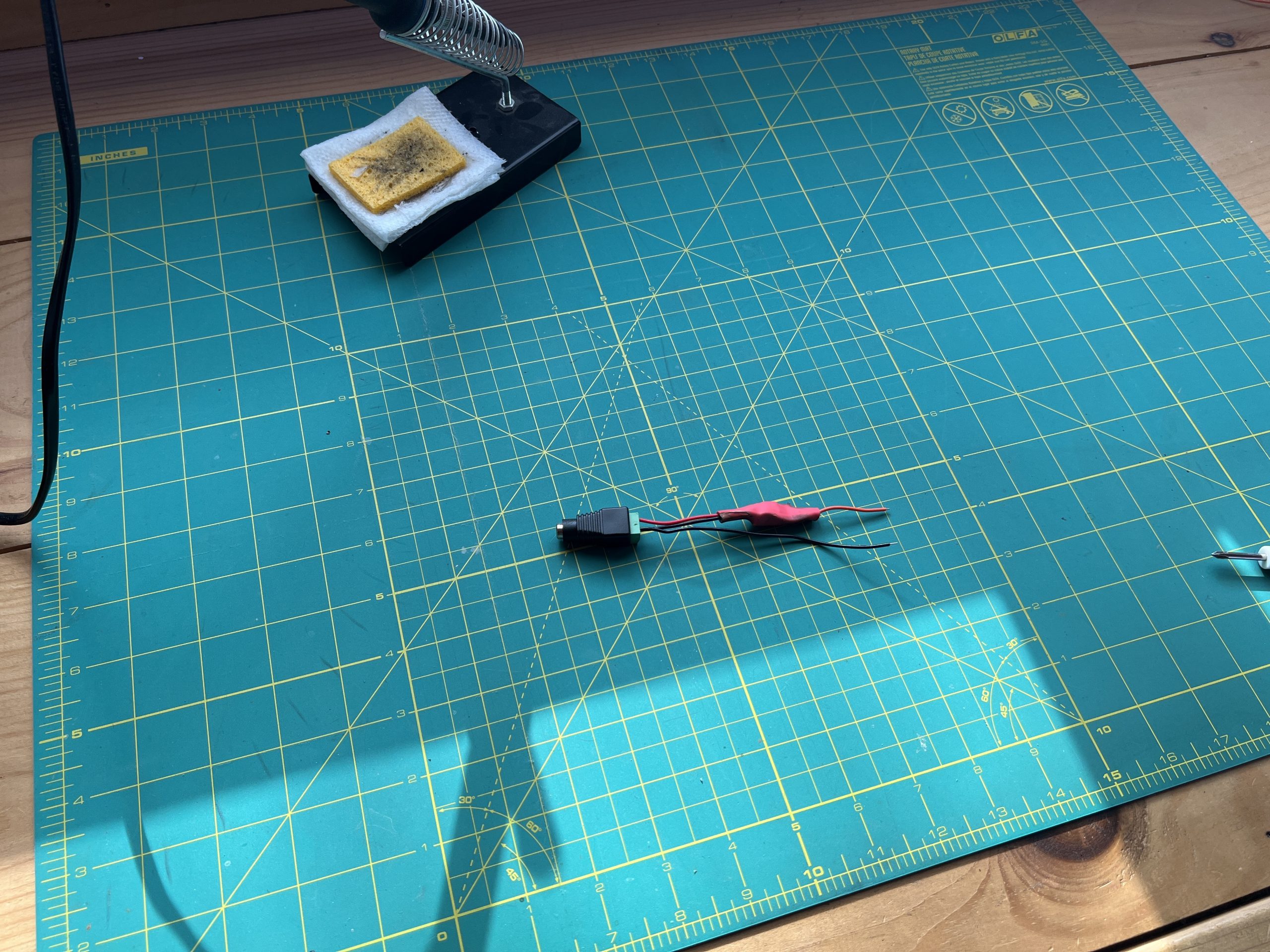
Disconnect power and elongate the wires on either sides of the connector.
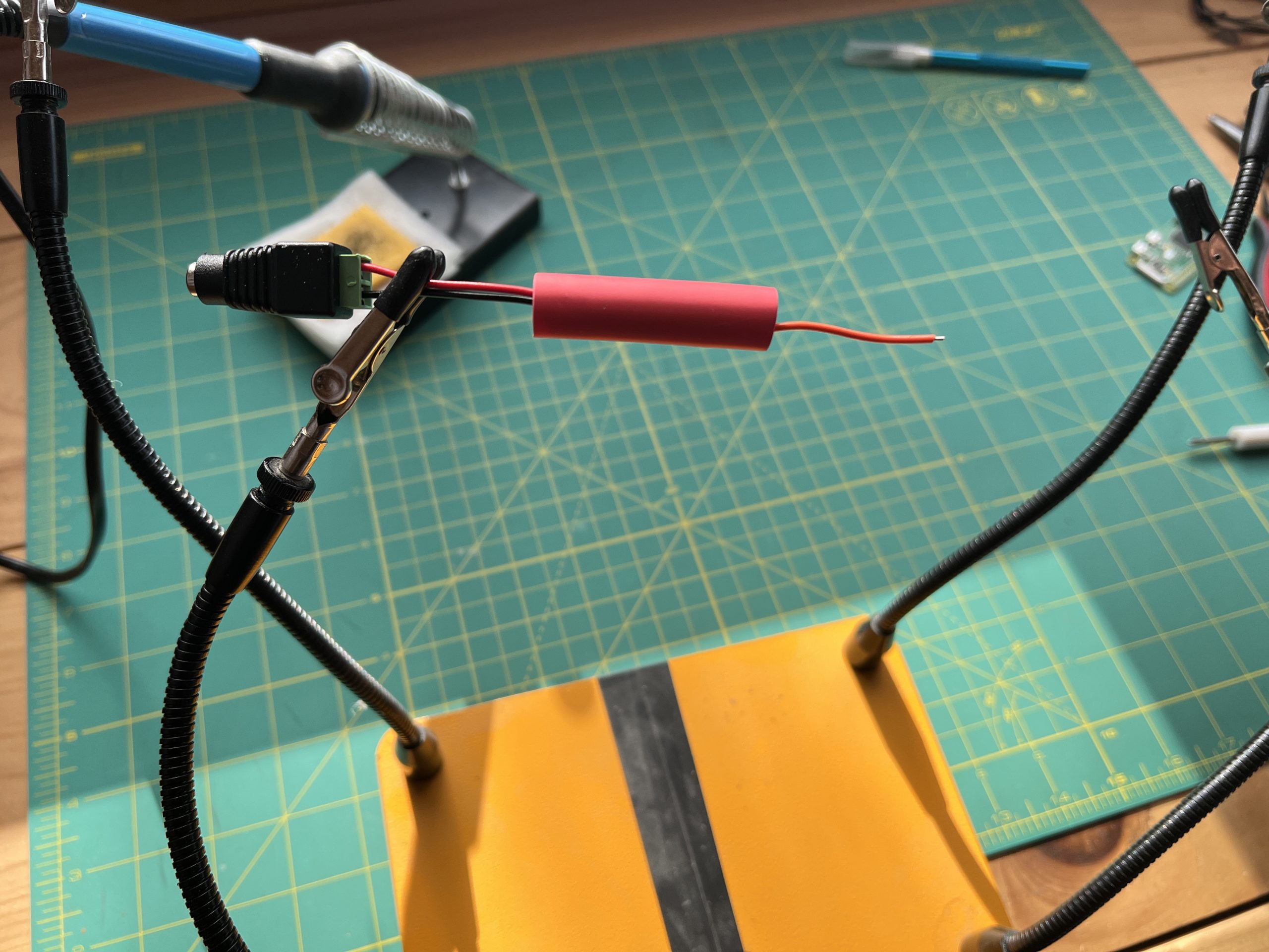
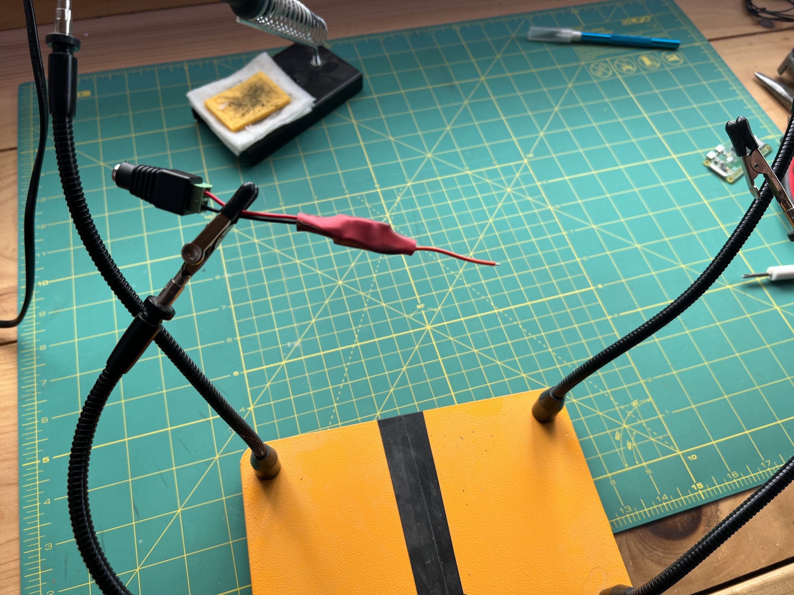
Slide the shrink tubing over it, making sure it covers beyond the regulator on either side, and heat it up until shrunk.

Get another black wire of the length of the regulator plus its wires.
Add it so the – side of the power connector.
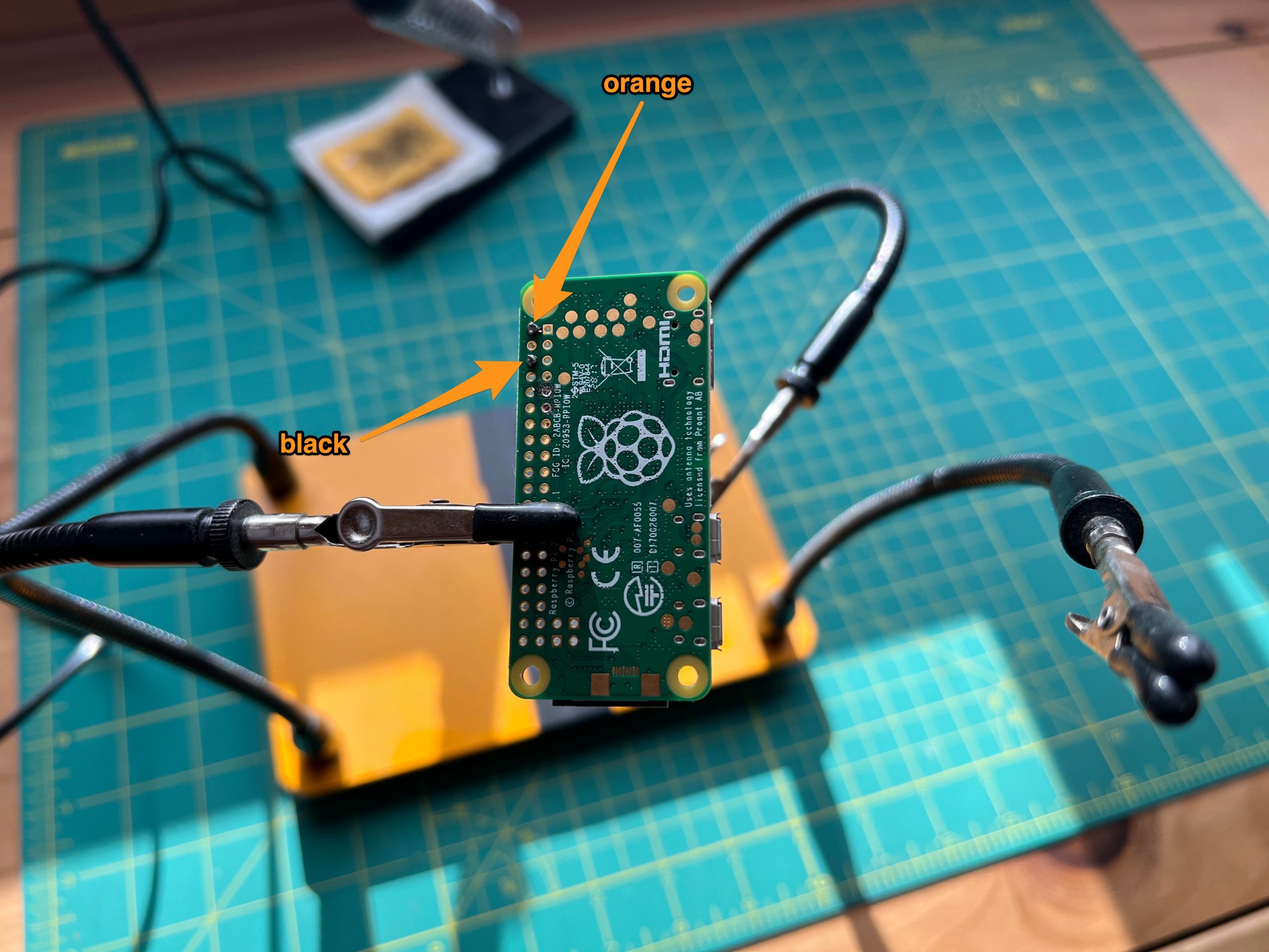
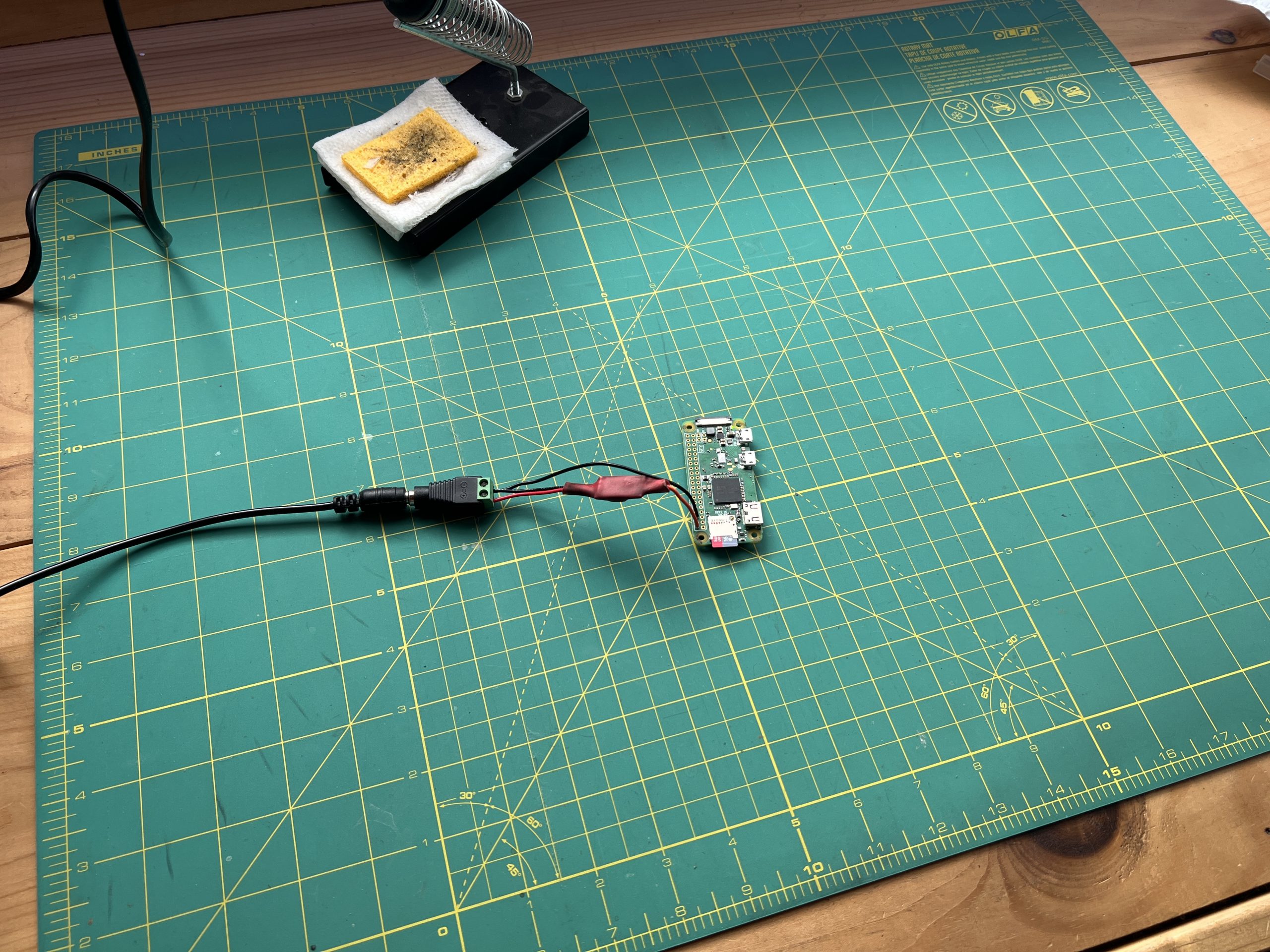
Grab the Pi and solder the orange wire to pin 2 (5V power), and the black wire to pin 6 (Ground). You can refer to https://pinout.xyz to make sure you are hitting the right pins.
You Pi is ready to be powered from our 12V circuit. But don’t do it just yet, first grab an SD card.
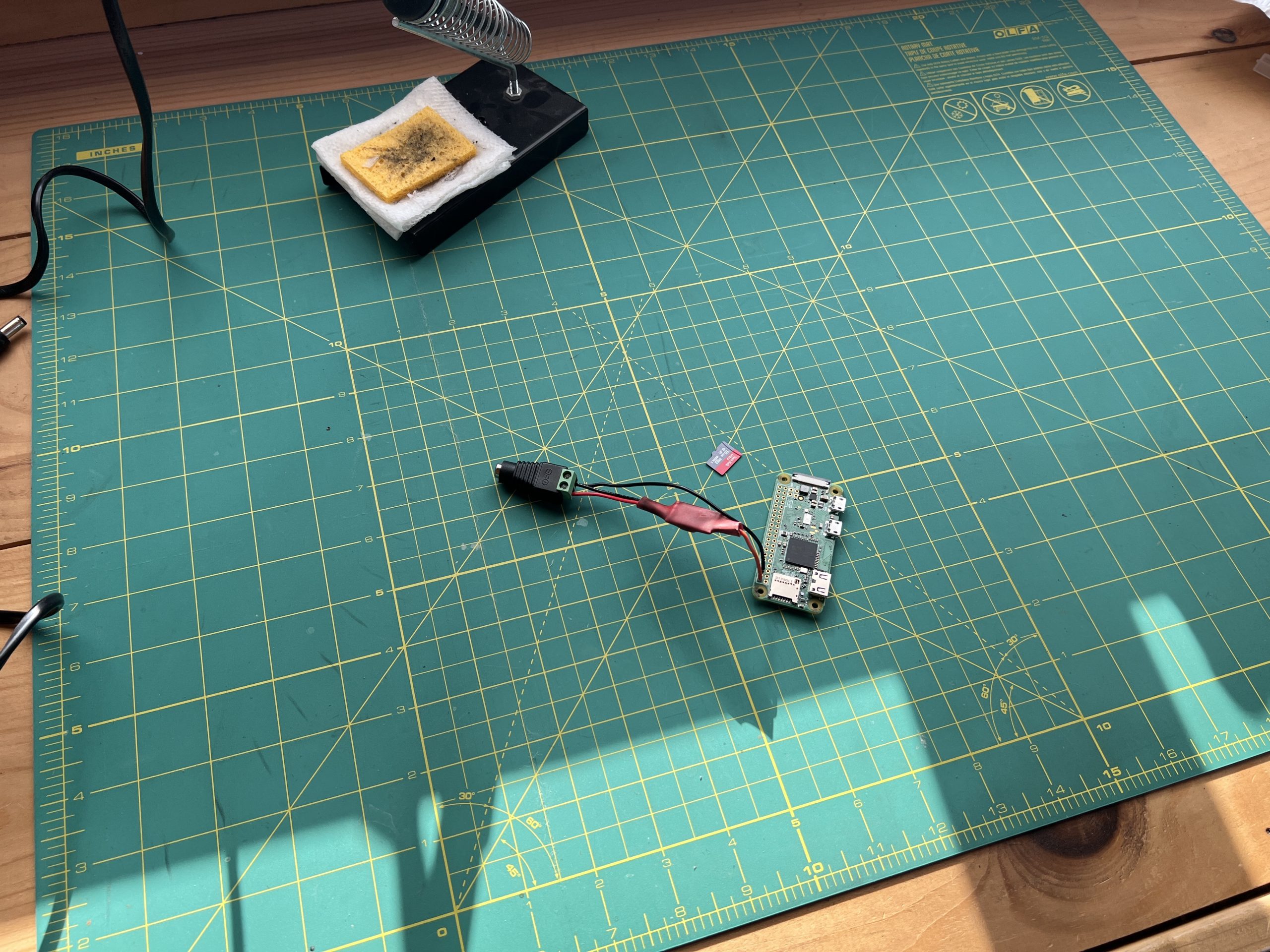
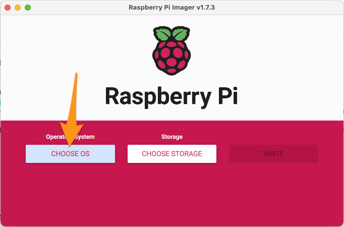
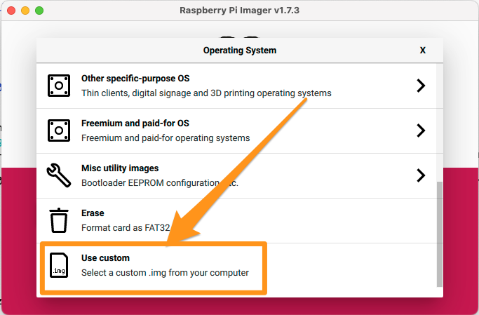
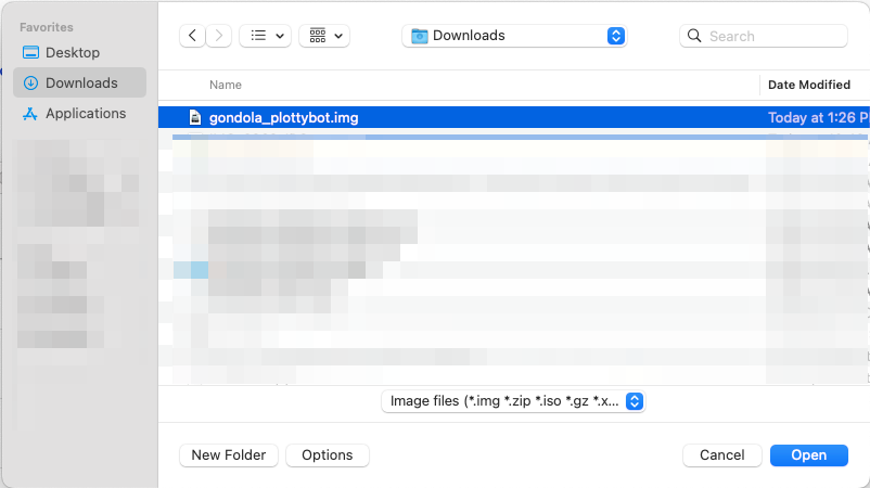
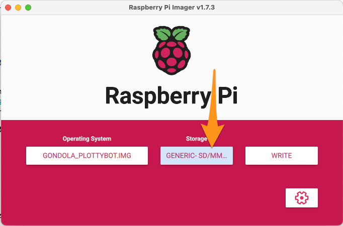
Download the PlottyBot SD Card image. Using the Raspberry Pi Imager, you can write it to your SD card. The steps are as follows.
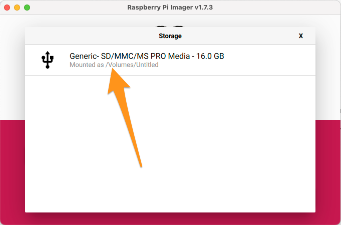
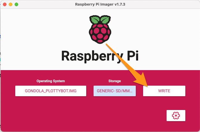
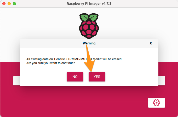
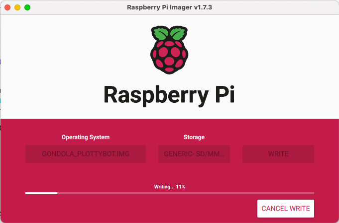
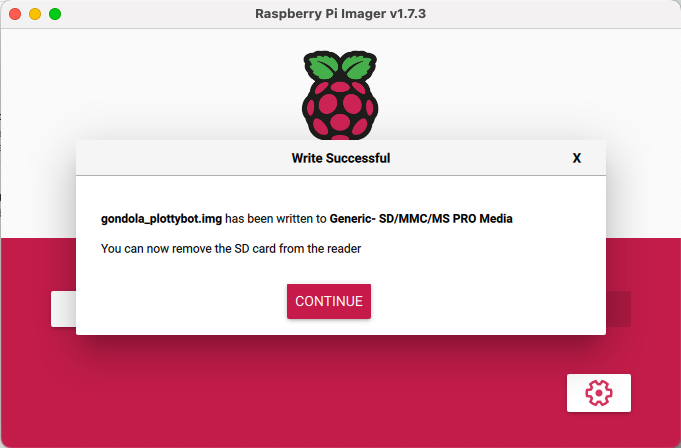
You can stick your newly imaged SD card in the Pi, and now you can power it on.
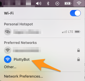
And now we wait :). The first boot can take 10 to 15 minutes, that’s right! The image comes pre-loaded with a lot of packages, and they are being installed on a fairly slow computer. You’ll know it finished when you see a new Wifi network show up called PlottyBot. You can connect to this new Wifi network with password 1234567890.
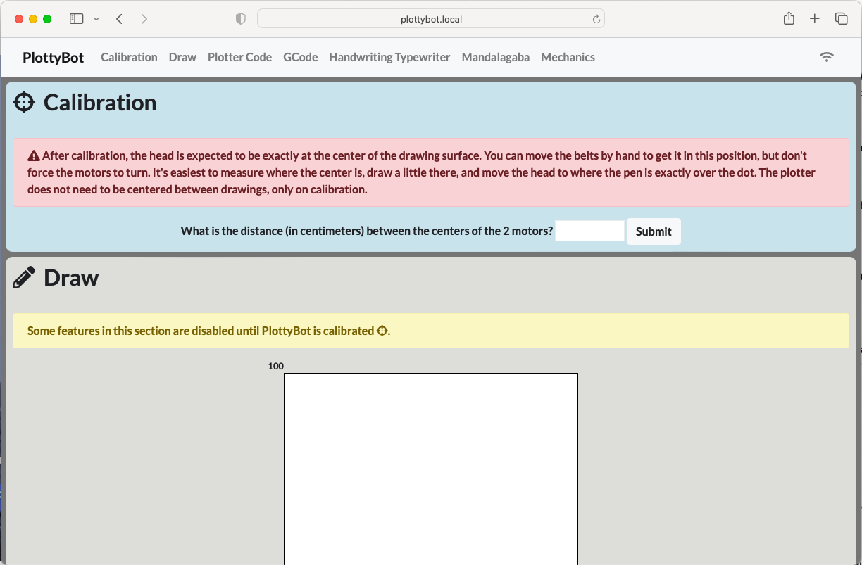
Then point your browser to http://plottybot.local (or http://10.0.0.5 if the former doesn’t work). You should see something like this:
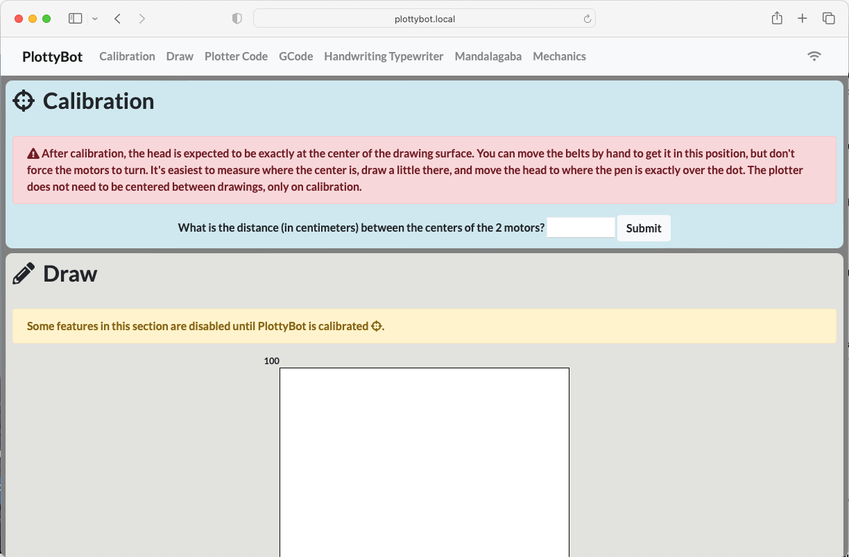
Looking good! You can now disconnect your Pi from power.
3. Managing Wires to the Terminals
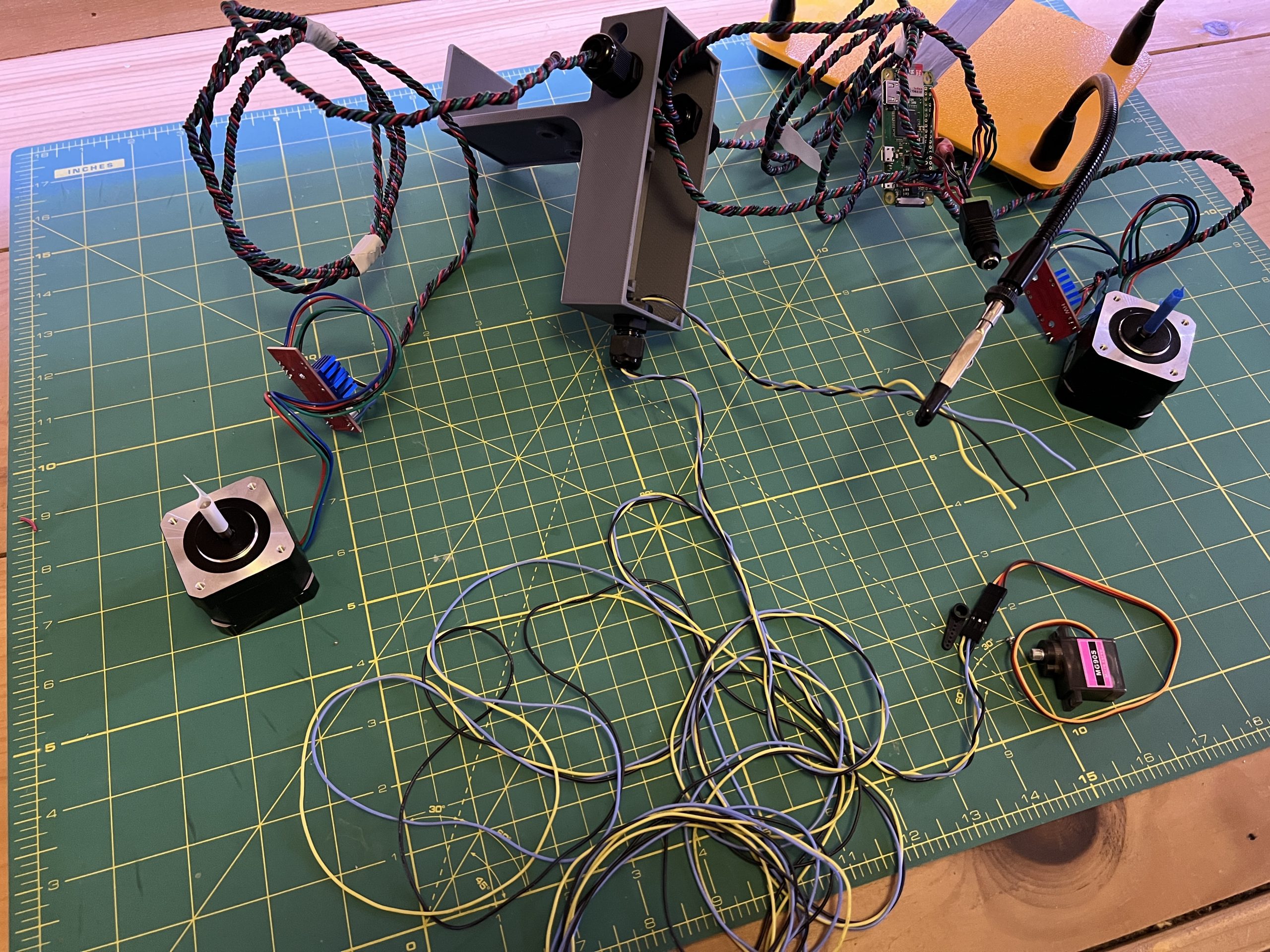
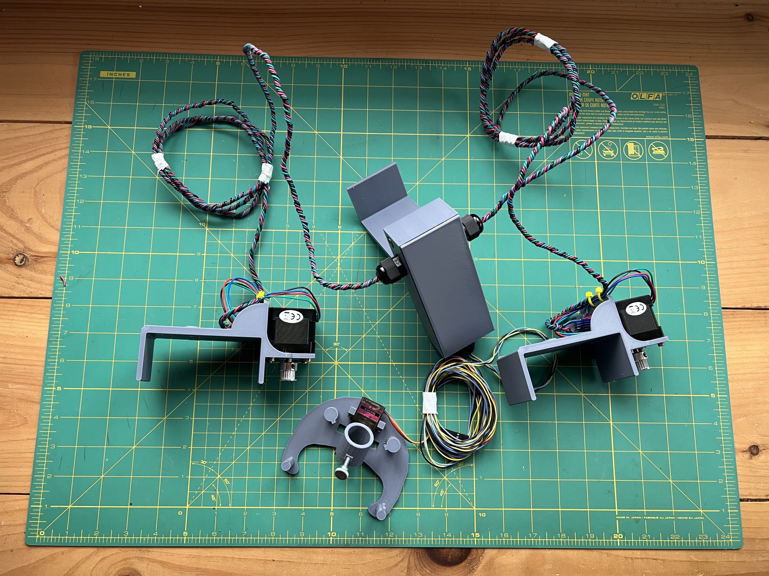
This plotter can technically be deployed at any size. In reality, going too long a distance will impact electronics and the weights keeping belts straights. At this moment though, you should decide how big a plotter you want, or at least what its maximum size should be. Here’s how the plotter is deployed to try and help you determining wire length.
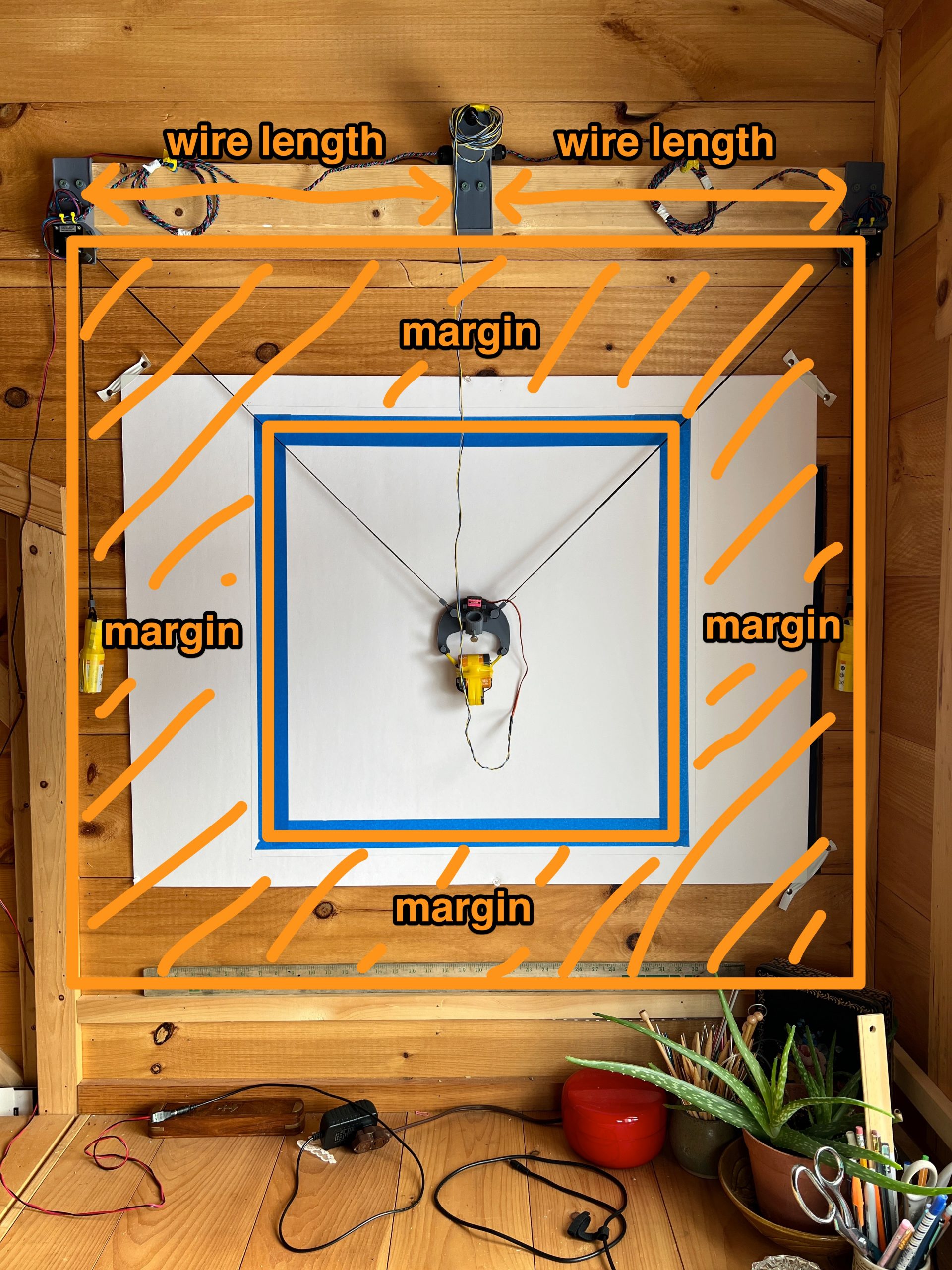
The “wire length” in the above picture is what we’ll be cutting to. In this case, I went about 2 meters on both sides and looped the extra. This way I can always redeploy the plotter on a larger canvas. Note that the margin is necessary and baked into the software. It is impossible to get accurate motion near the extremities, and so it easier to avoid them and deploy the plotter on a larger area if needs be.
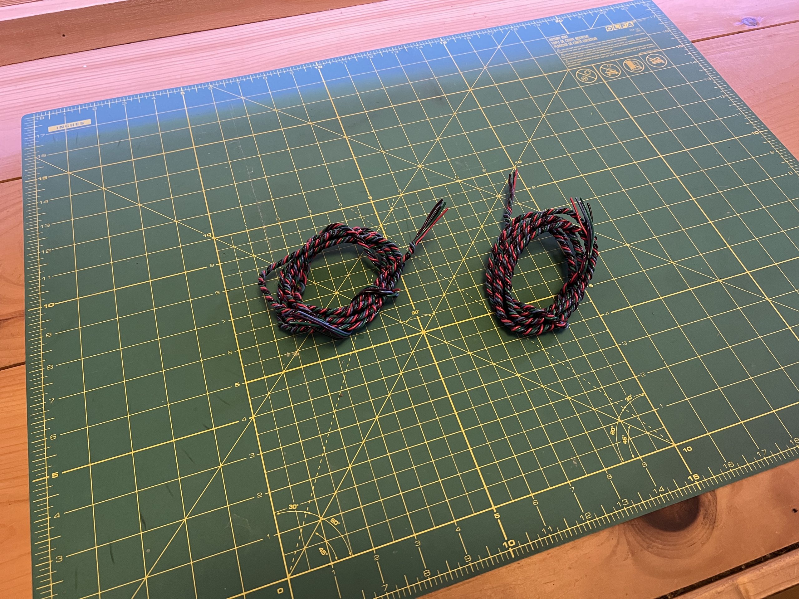
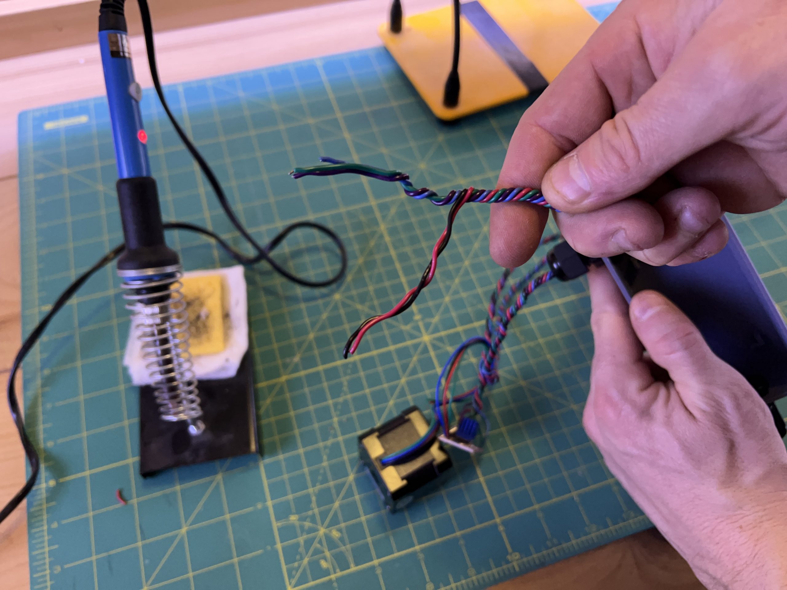
So let’s grab 5 wires of different colors, including a red and a black, and Cut them to your desired “wire length”. It will be messy for the next little bit.
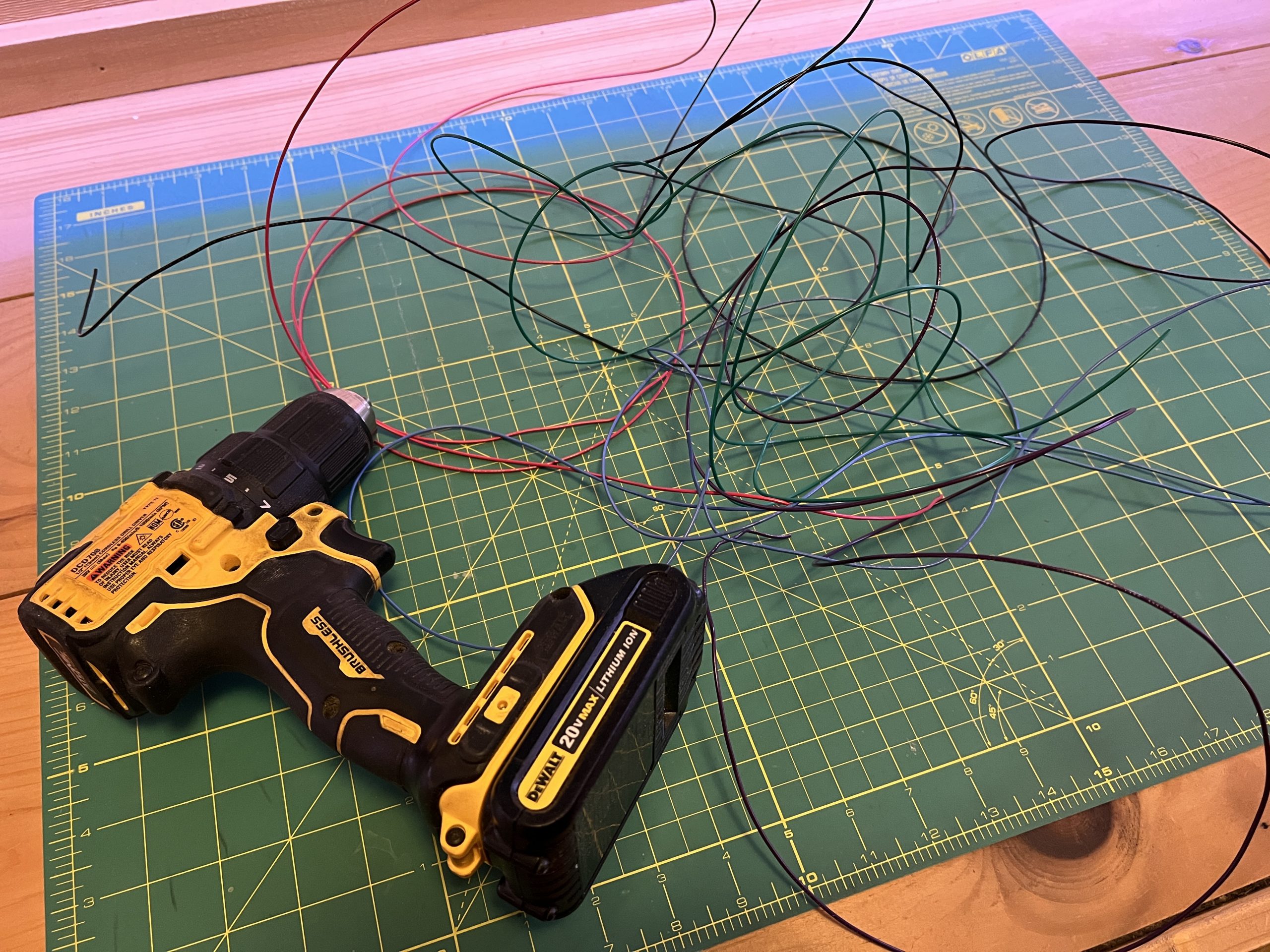
With the drill, we’re going to twist the wires together over their whole length. You can do this by hand, but it is slow and painful. Doing so with a drill is a lot faster but it’s still tricky to do this over 2 meters, having someone else help is nice.
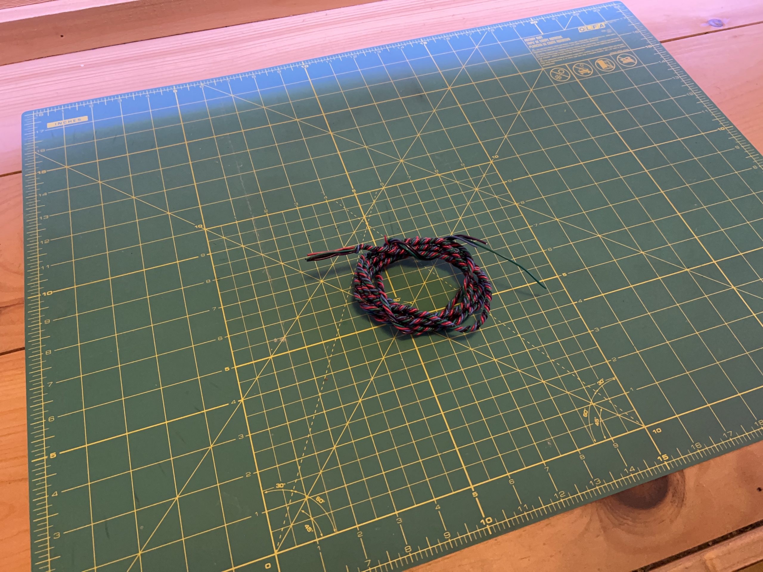
Then make another one just like it with another 5 wires :).
4. Left Motor
parts
Acquired
– stepper motor x1
– stepper motor driver x1
– heat sink x2
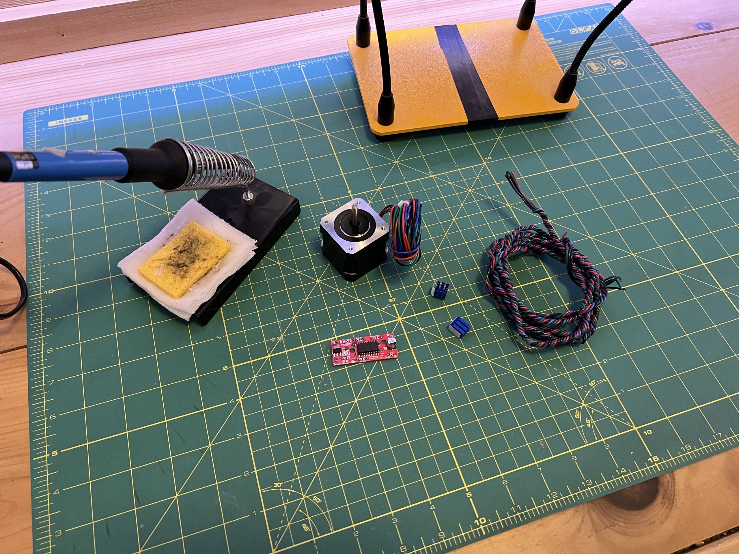
Grab a wire bundle you just made, and tidy up the ends. Snip them to equal length.
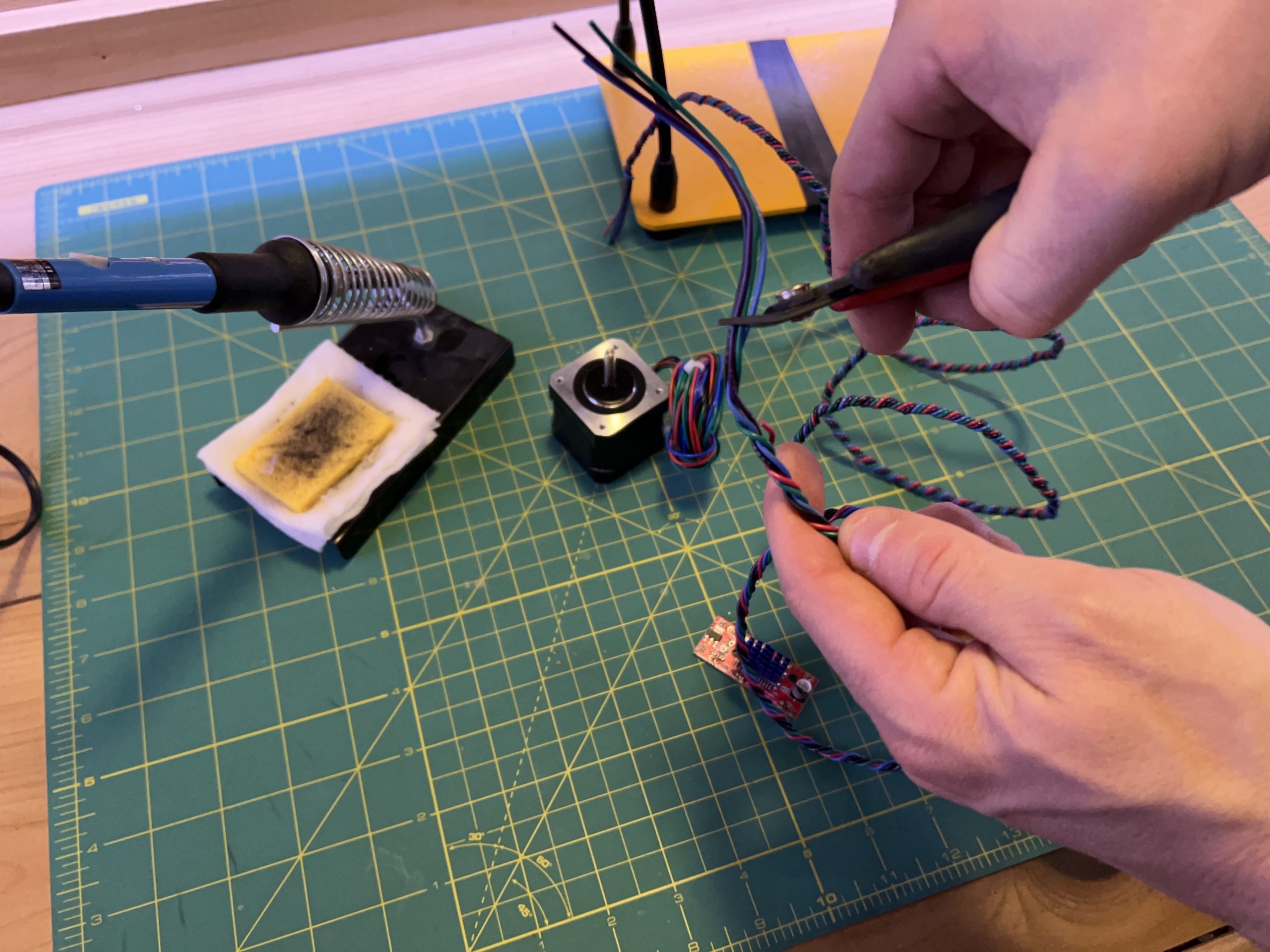
Spread them out a bit so we know what we’re working with and strip them.
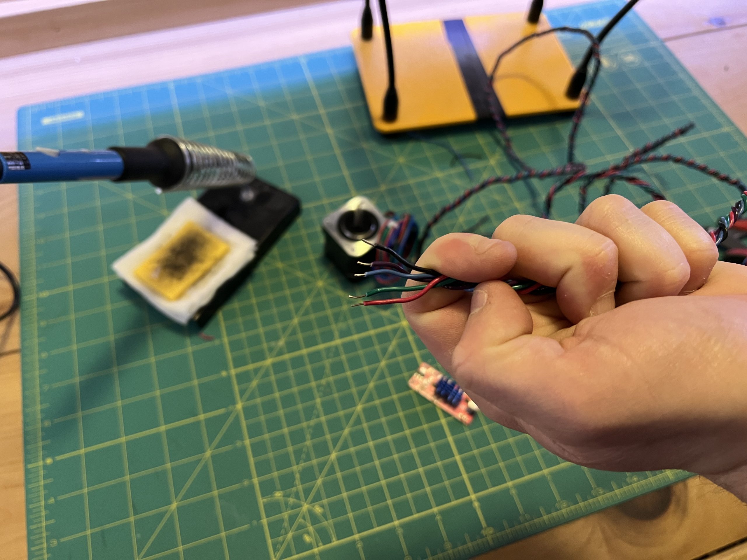
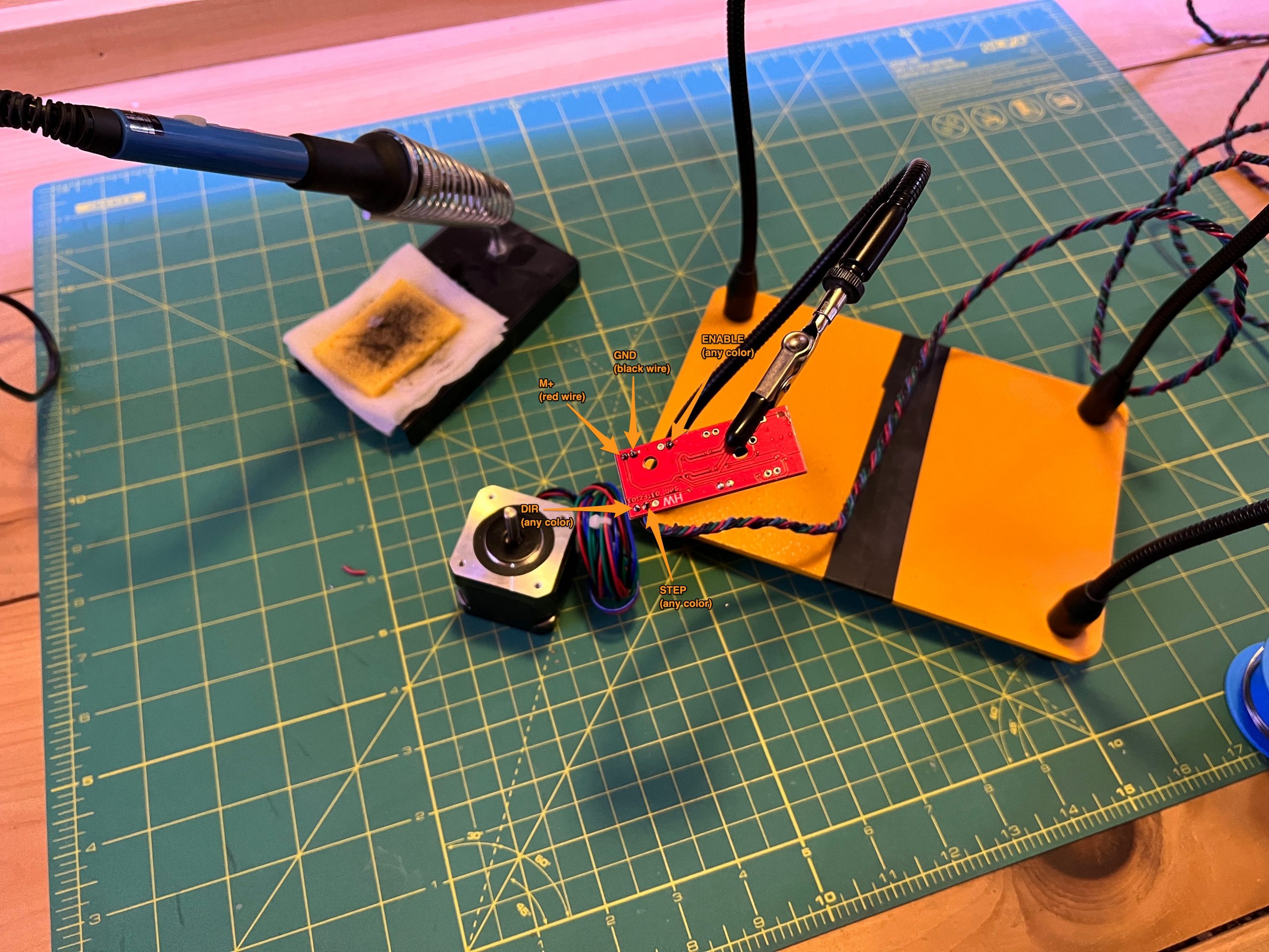
Then solder them on the stepper driver as follows.
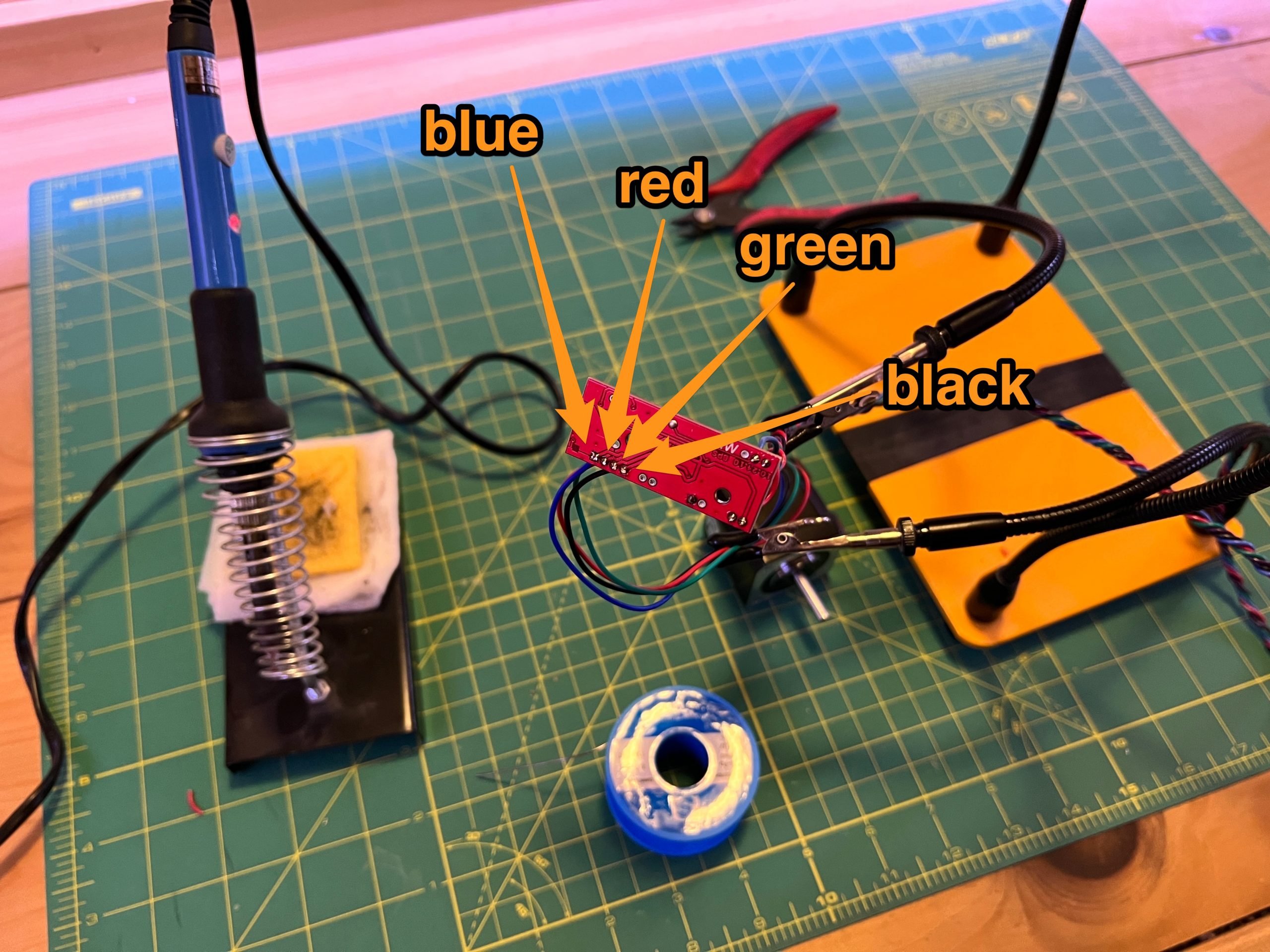
Cut and strip the wires coming out of the stepper motor, leaving 15 to 20 cm of length.
Solder them to the driver as follows.
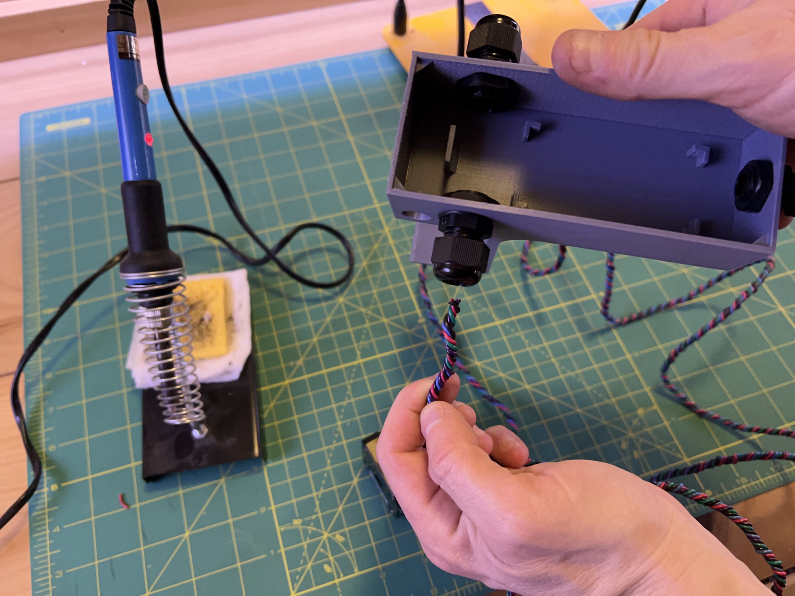
Pass the other end of your wire bundle into the left gland of the logic box.
Isolate the red & black wires from the other 3.
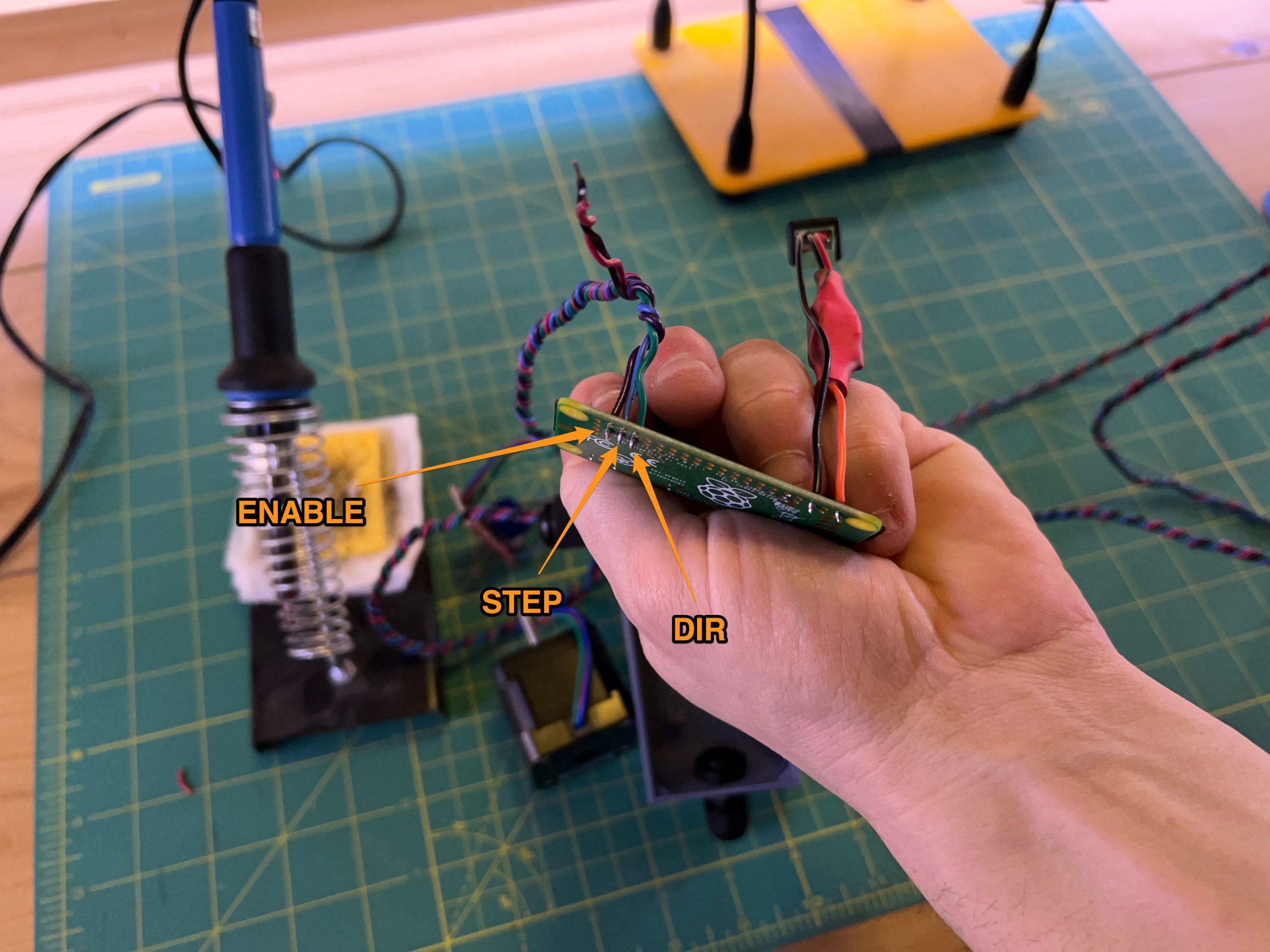
Solder the 3 wires to the Pi, following the colors such that:
– Pi pin 37 (GPIO 26) is connected to the stepper driver’s ENABLE pin
– Pi pin 35 (GPIO 19) is connected to the stepper driver’s STEP pin
– Pi pin 33 (GPIO 13) is connected to the stepper driver’s DIR pin
Grab the red & black from that same bundle and connect them to the power connector’s + & –.
Stick the 2 heatsinks on the stepper driver’s chip.

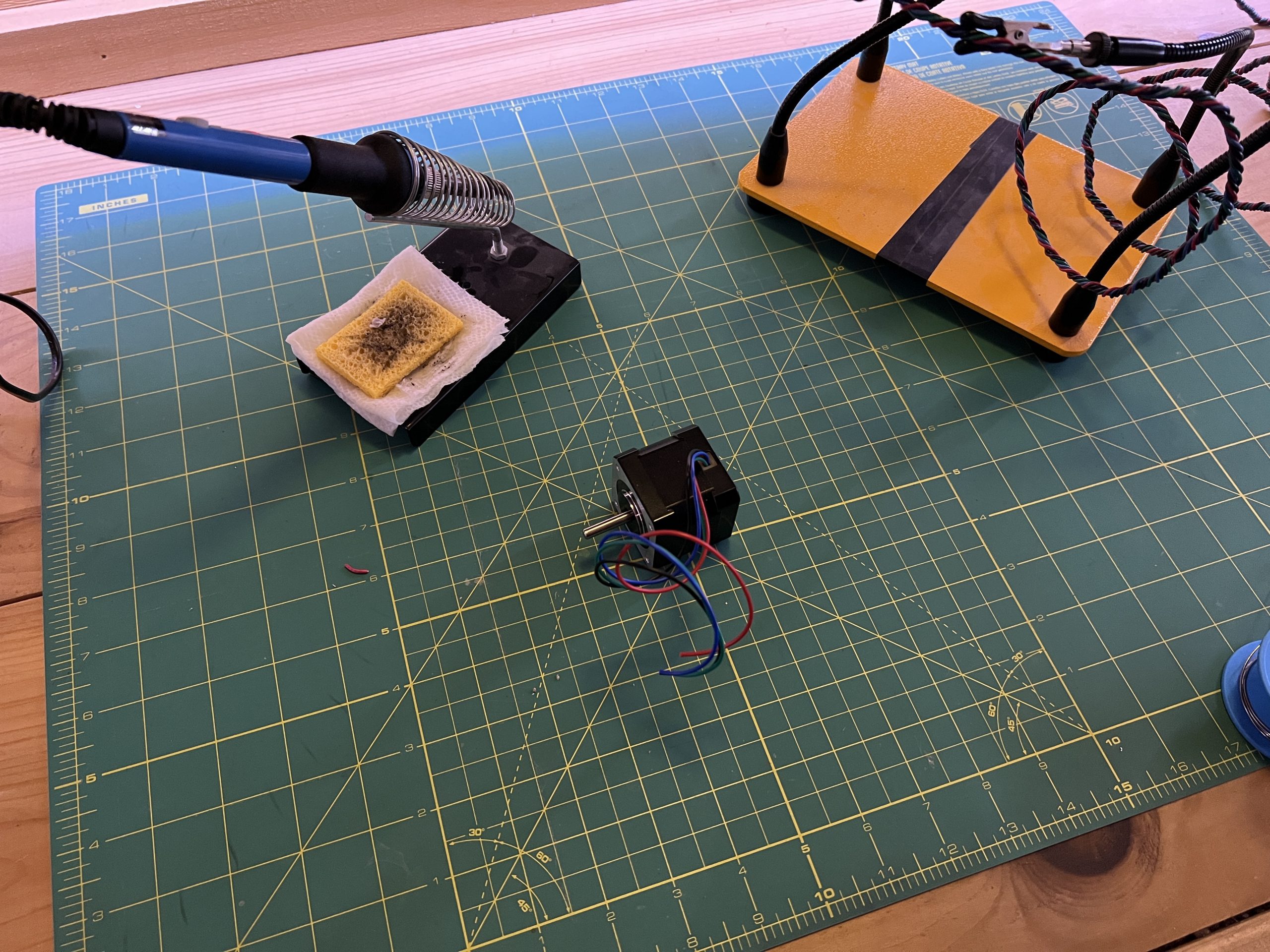
Power on the Pi, hopefully no smoke comes out :). You can stick a little piece of tape on the motor’s shaft if you want, we’re going to test it and it helps visualize motion.
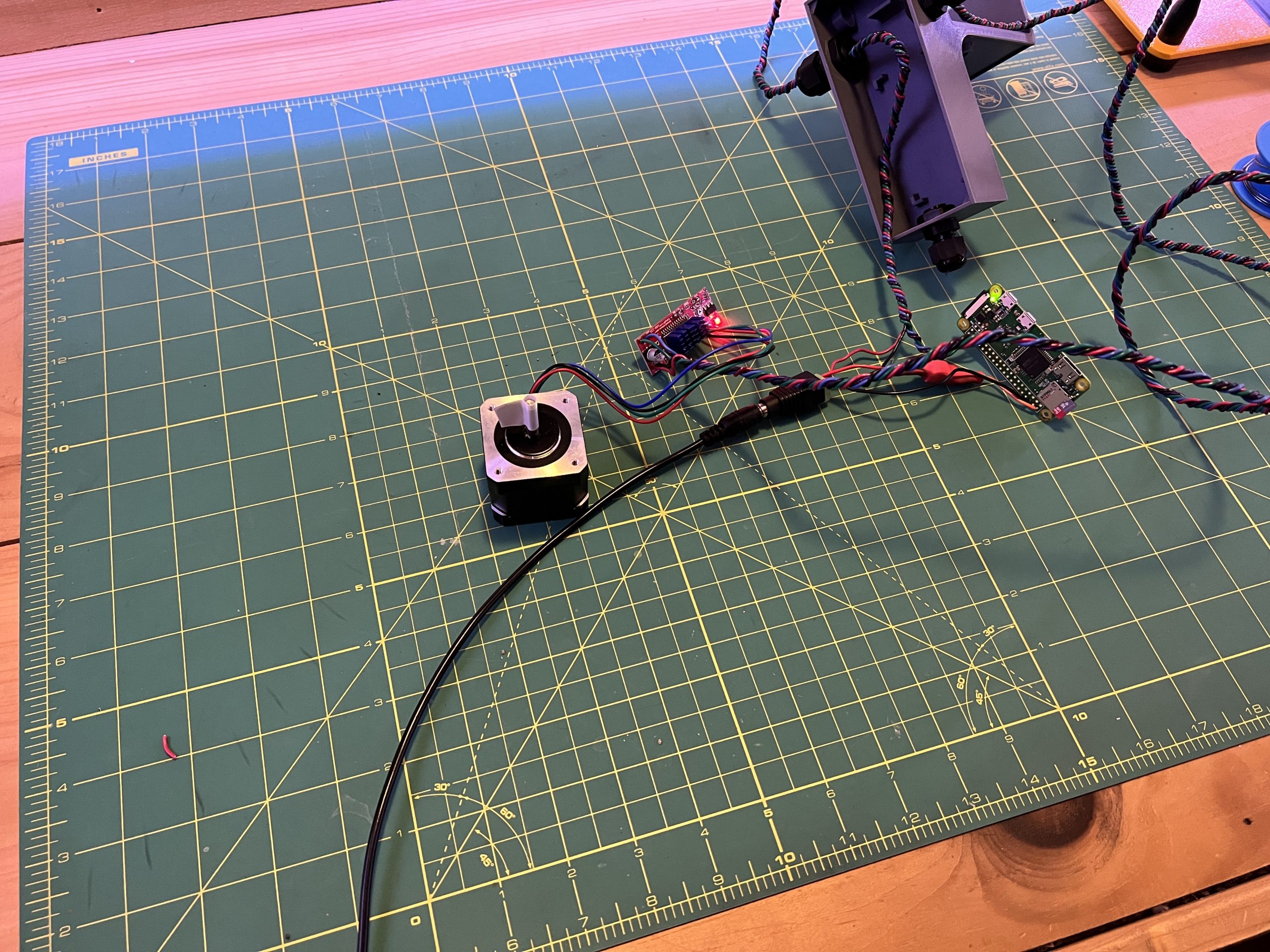
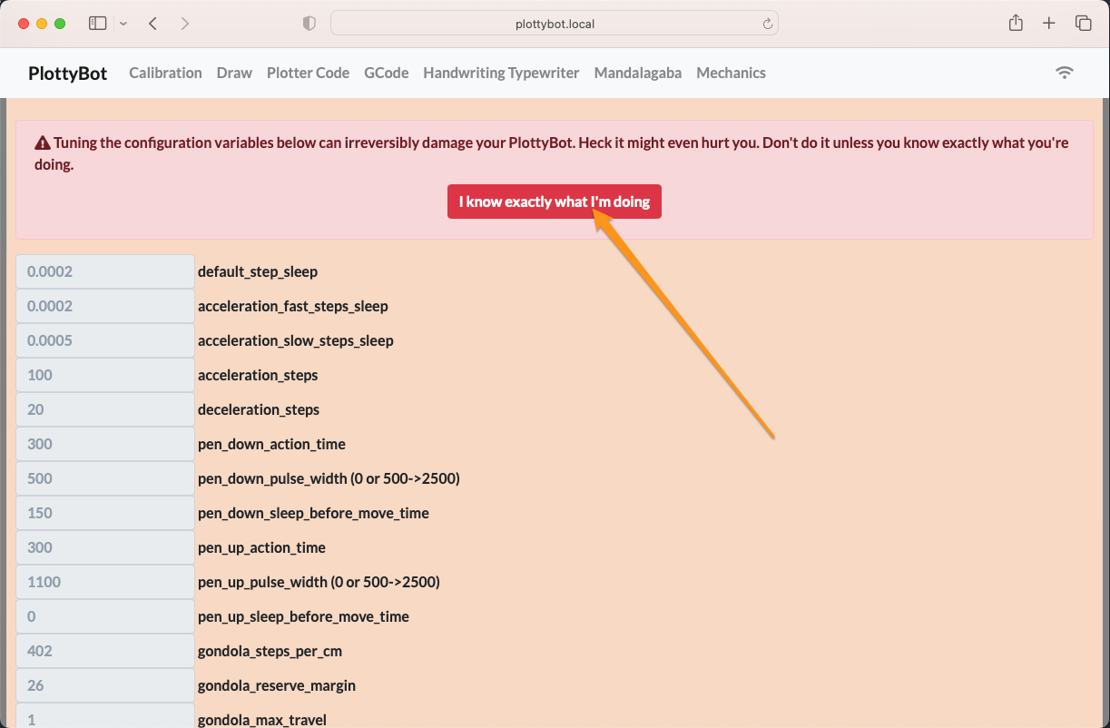
Once you see the PlottyBot wifi, connect to it and point your browser to http://plottybot.local (or http://10.0.0.5). Scroll all the way down to the “Mechanics” section.
You know exactly what you’re doing right?
Then click the “Test Bottom Stepper Motor” button. (Note: at some point I’ll rename this to the Left Stepper Motor that it is, this is a liability of sharing a software stack with a tabletop plotter).
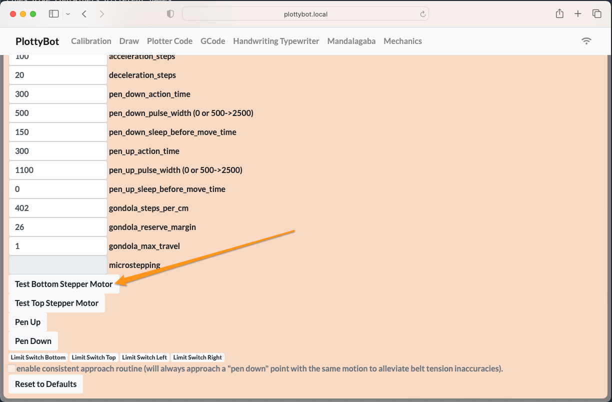
You should see the motor do 1/8 of a turn and back, then 1/4, 1/2 and finally a full turn. If you do not, stop here before going further. Check your that your connections go to the right pins, and are clean. Drop a comment if you’re stuck.

You can disconnect power.
5. Right Motor
parts
Acquired
– stepper motor x1
– stepper motor driver x1
– heat sink x2
This is a repeat of the Left Motor, with
– Pi pin 40 (GPIO 21) connected to the stepper driver’s ENABLE pin
– Pi pin 38 (GPIO 20) connected to the stepper driver’s STEP pin
– Pi pin 36 (GPIO 16) connected to the stepper driver’s DIR pin
Don’t forget to go through the right gland before soldering. And add on red & black so the power connector. When you are done you’ll have both motors connected.
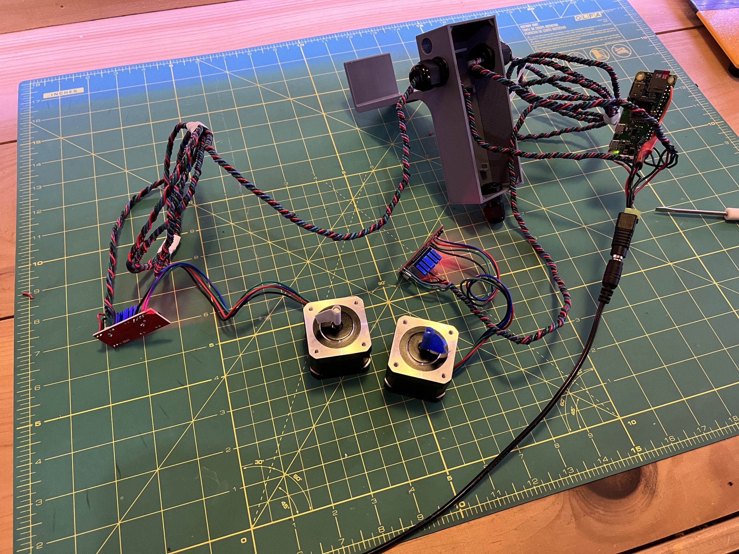
You can test it with the web interface’s “Test Top Stepper Motor” button.
6. Servo Motor
parts
Acquired
– 30AWG flexible wiring
– servo motor
– Dupont connector kit (optional)
You do not need this particular sort of wiring, but you do want light and flexible wiring. We are building the wire connecting the logic box to the gondola. It needs to float and not impact weight distribution so the belts are always straight.

Note: for my plotter, I’m crimping a Dupont connector to the end of the wire so I can easily connect/disconnect servo motors. You do not need to do this you can simply cut, strip and connect wires making sure they are insulated from each other with shrink tubing or electrical tape. Servo motors will die and so I like an easy swap, but the MG90S is very robust and rarely needs it.
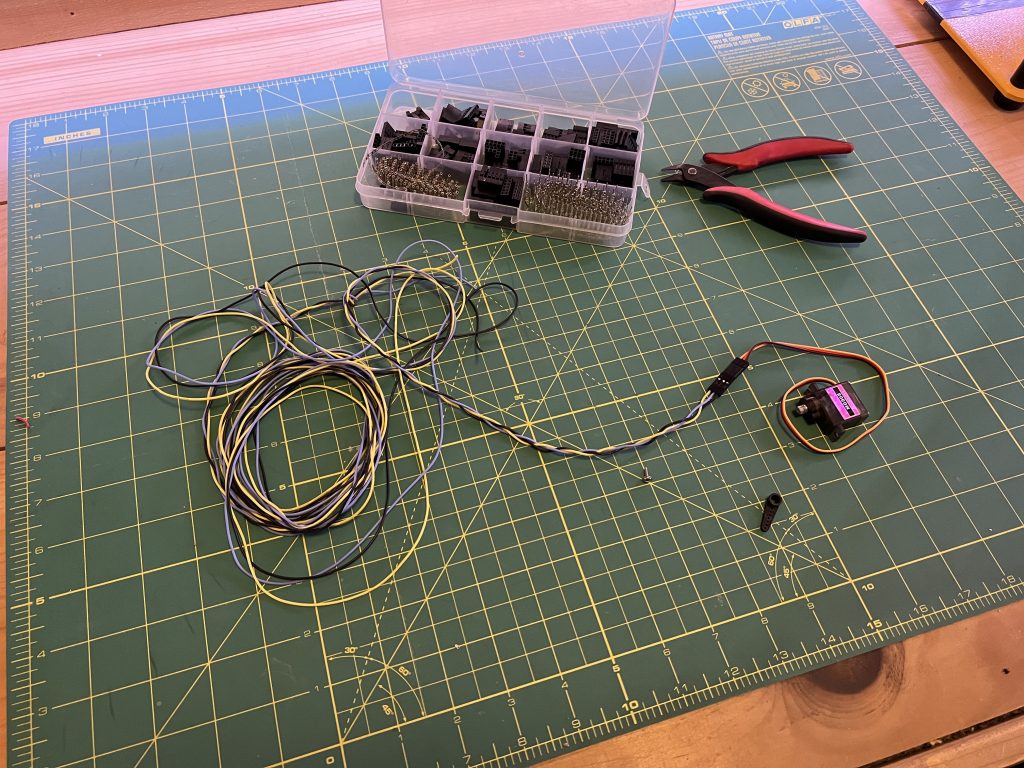
Grab 3 wires of different colors and braid them lightly so they stick together some. You want to make sure to have enough length that they can reach the bottom most positions of you maximum drawing size (plus a little slack).
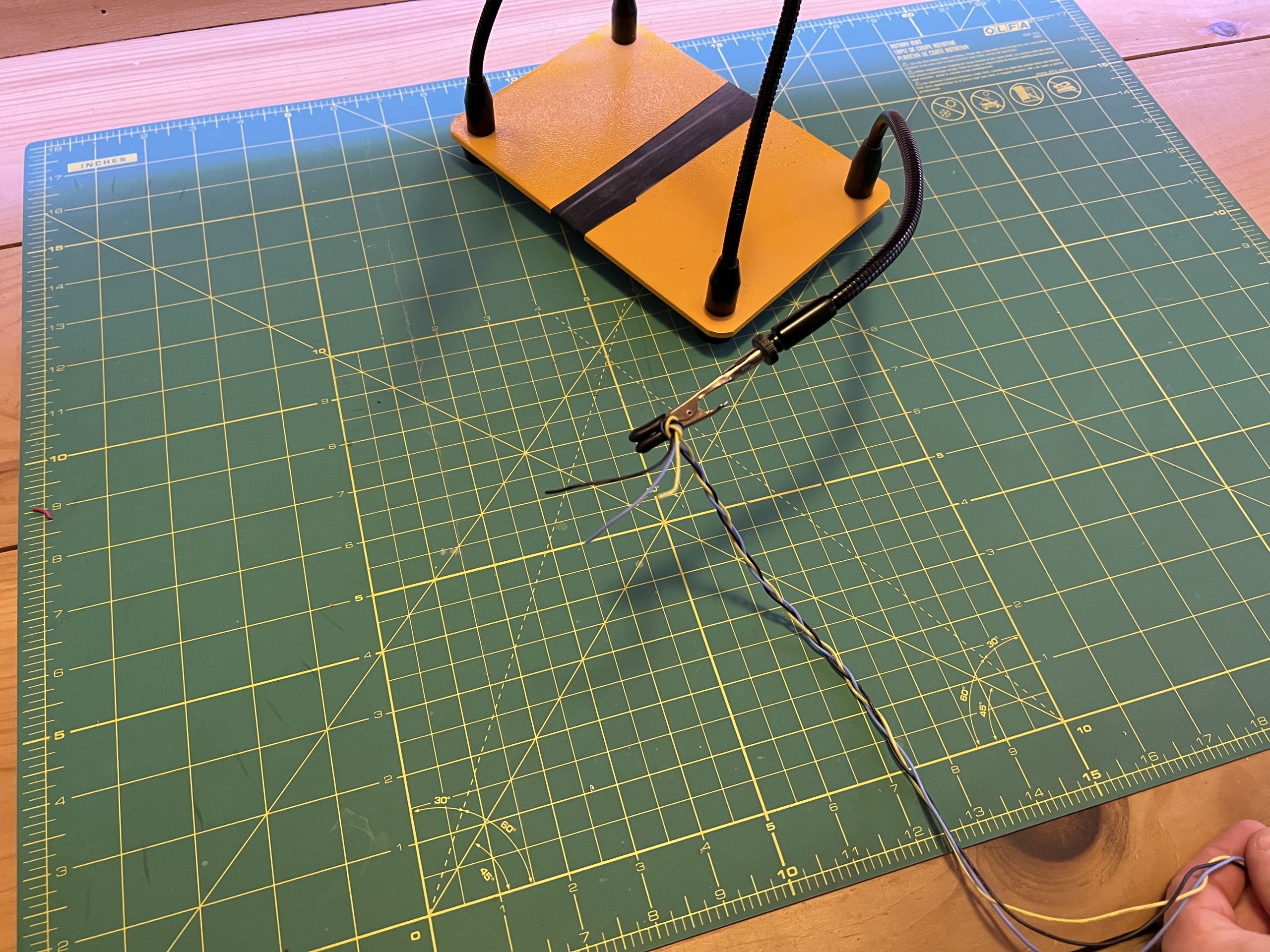
Then connect your wire bundle to the servo motor, with Dupont wires or strip/connecting them.
Run the other end through the remaining logic box gland.
And solder them to the Pi such that:
– Pi pin 9 (Ground) is connected to the servo’s brown wire
– Pi pin 4 (5V Power) is connected to the servo’s orange wire
– Pi pin 16 (GPIO 23) is connected to the servo’s yellow wire

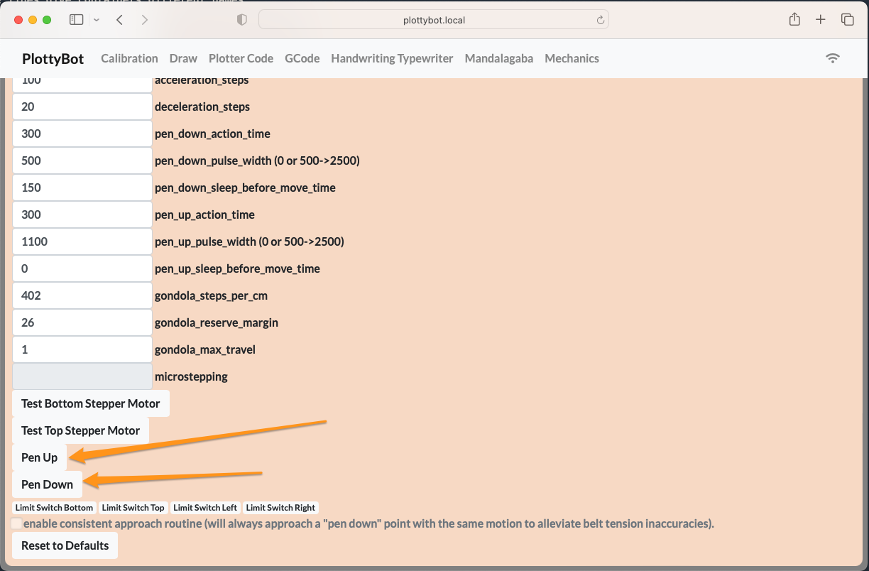
Power on the circuit, go to the mechanics section and try the “Pen Up” and “Pen Down” buttons.
Now is a good time to attach the little arm to the servo motor, and to align it with the Pen Up and Pen Down positions.
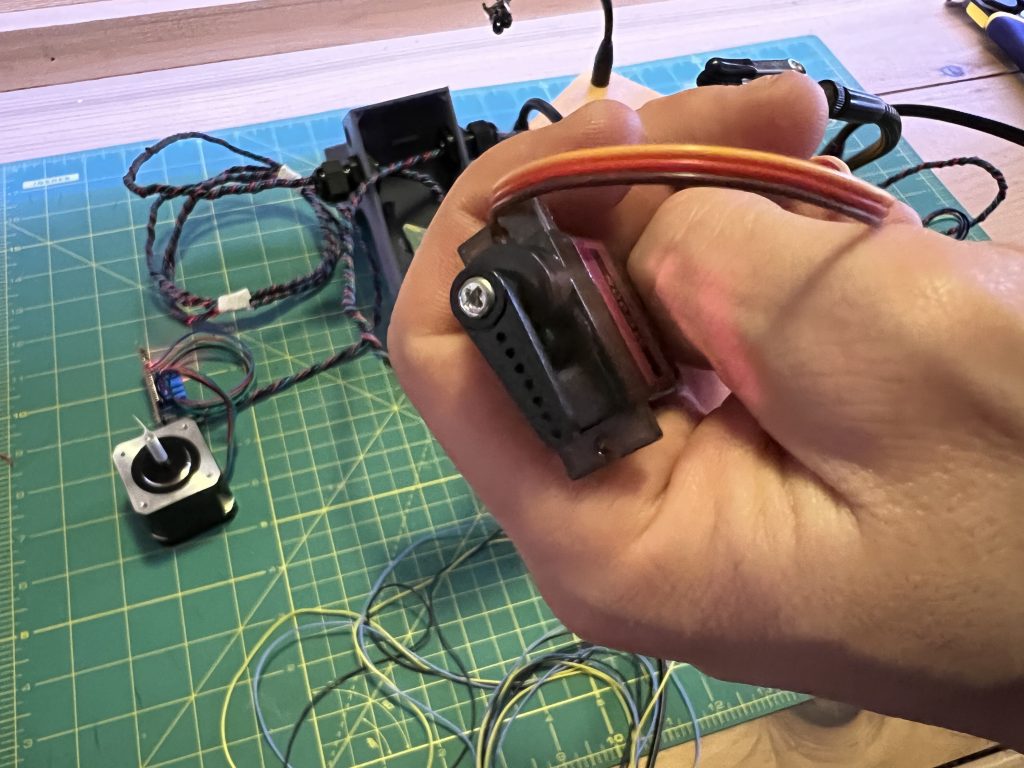
This is the Pen Down position 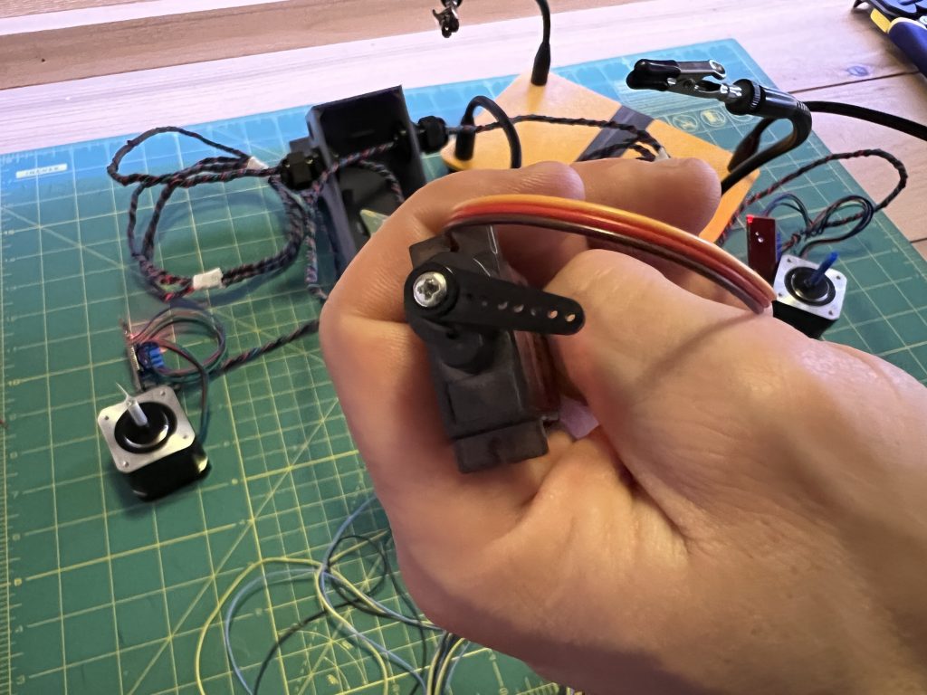
And this is the Pen Up position (the arm pushes the gondola away from the drawing surface)
7. Fitting In the Logic Box
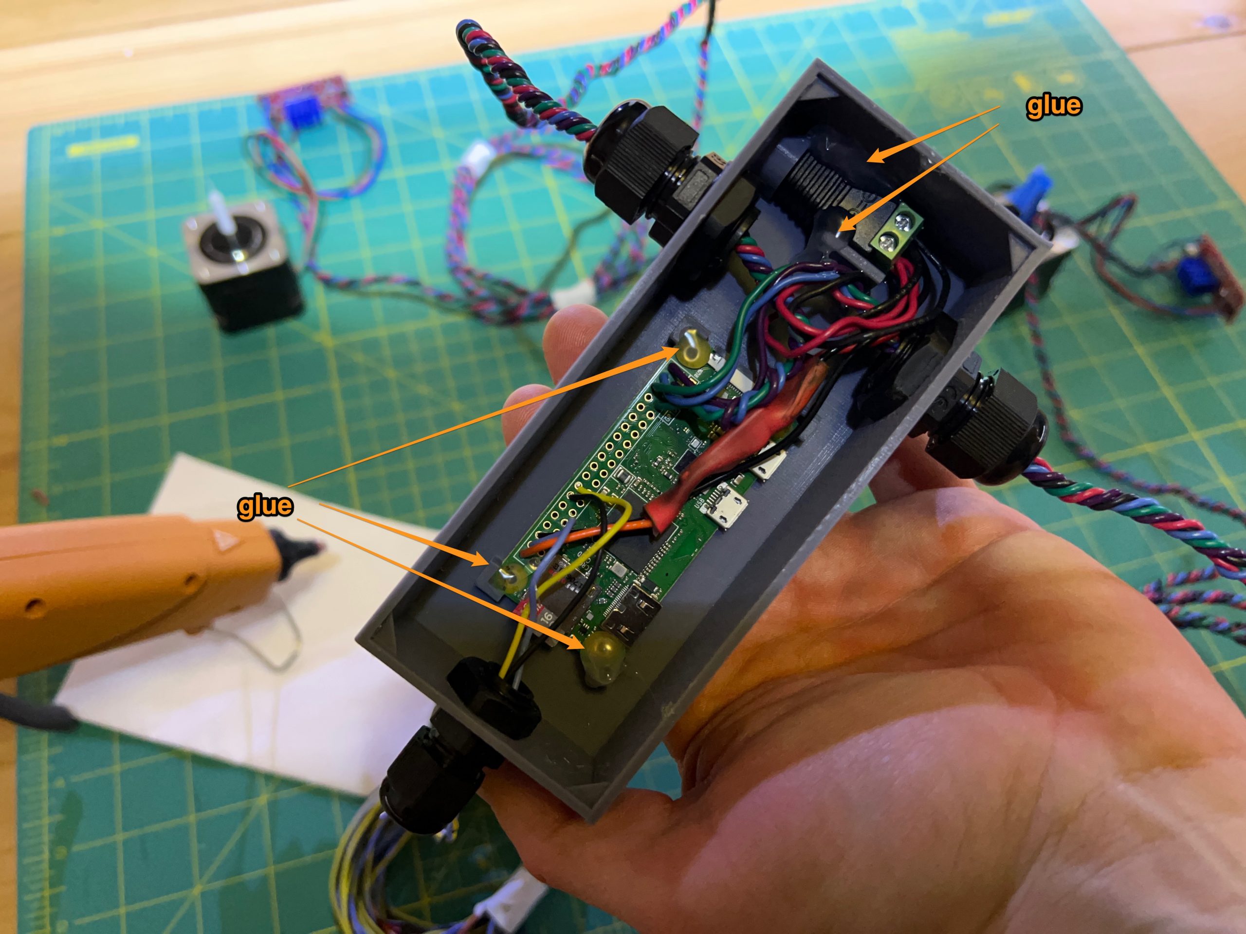
Ok! We are done with the electronics, let’s fit, attach, and tidy everything.
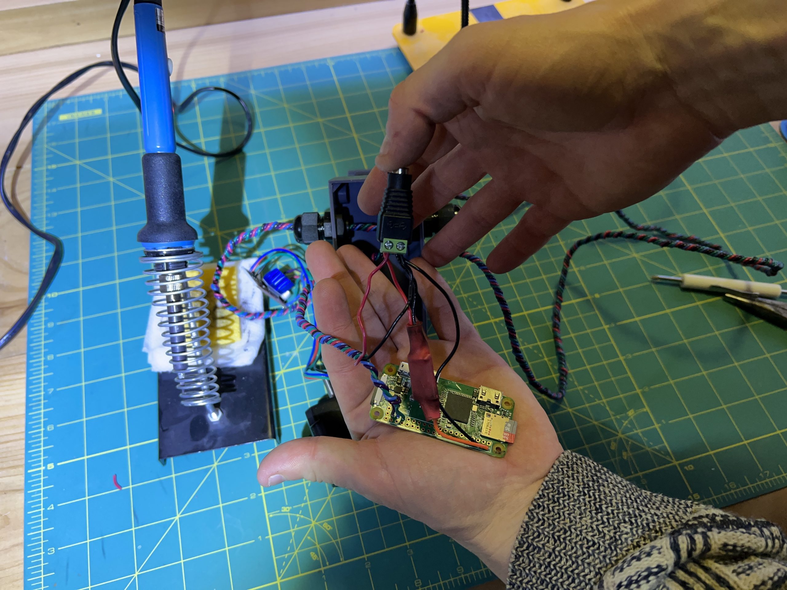
Carefully fit the power connector and the Pi in the logic box. Make sure to not put too much stress on the wire connections. When things are in place, you can tack them with the glue gun. Don’t put too much glue everywhere, just a few tacks to keep things from moving.
8. Motor Mounts
Parts
3D Printed
– motor_holder_x2
Acquired
– M3x8 bolt x8
– washer x8
– zip ties
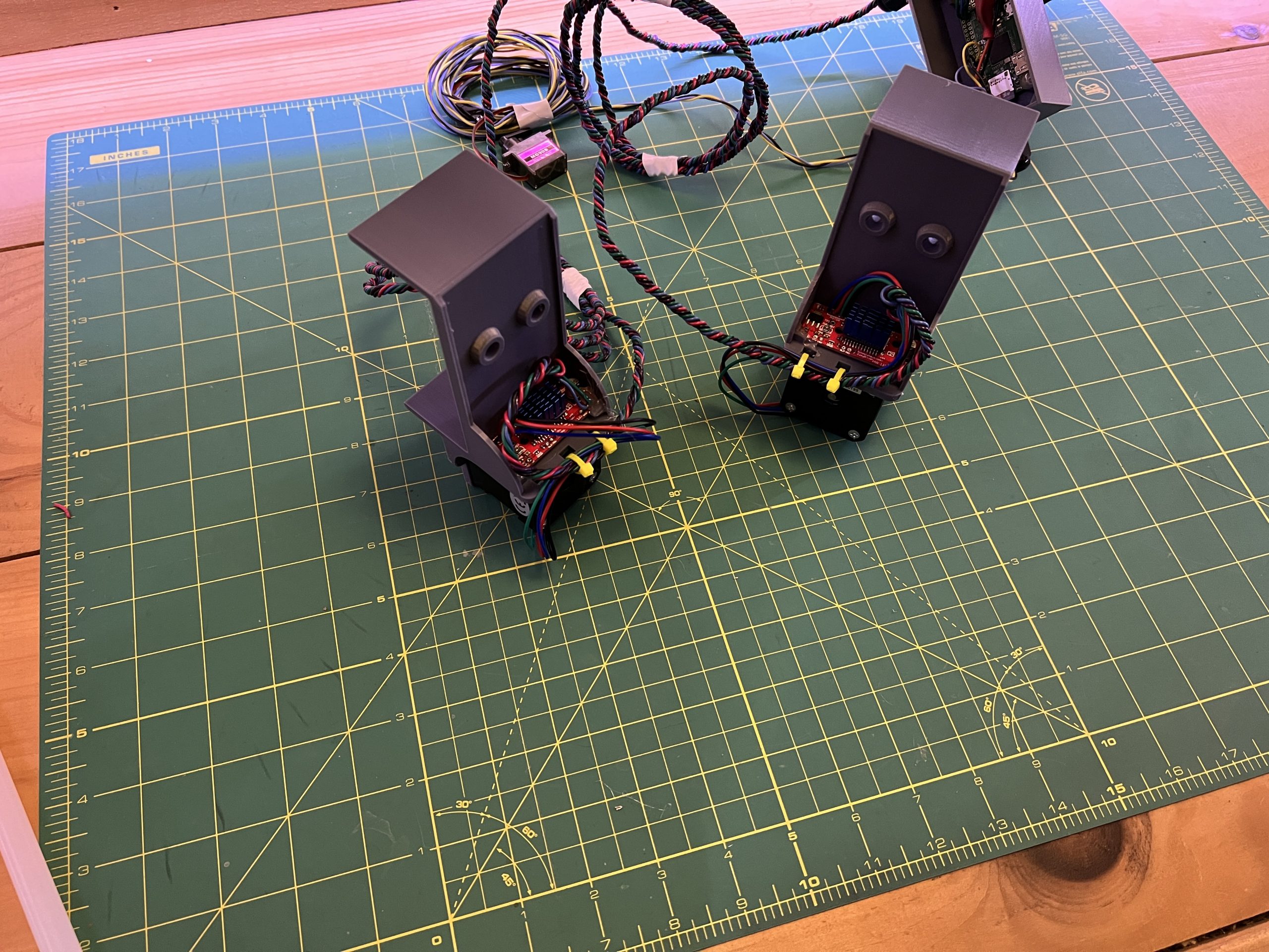
Fasten the stepper motors to their mounts with the bolts & washers.

Tack glue the stepper motor drivers in their holders, and zip tie wires tightly so that pulling on wires will not result in stress on the connectors.
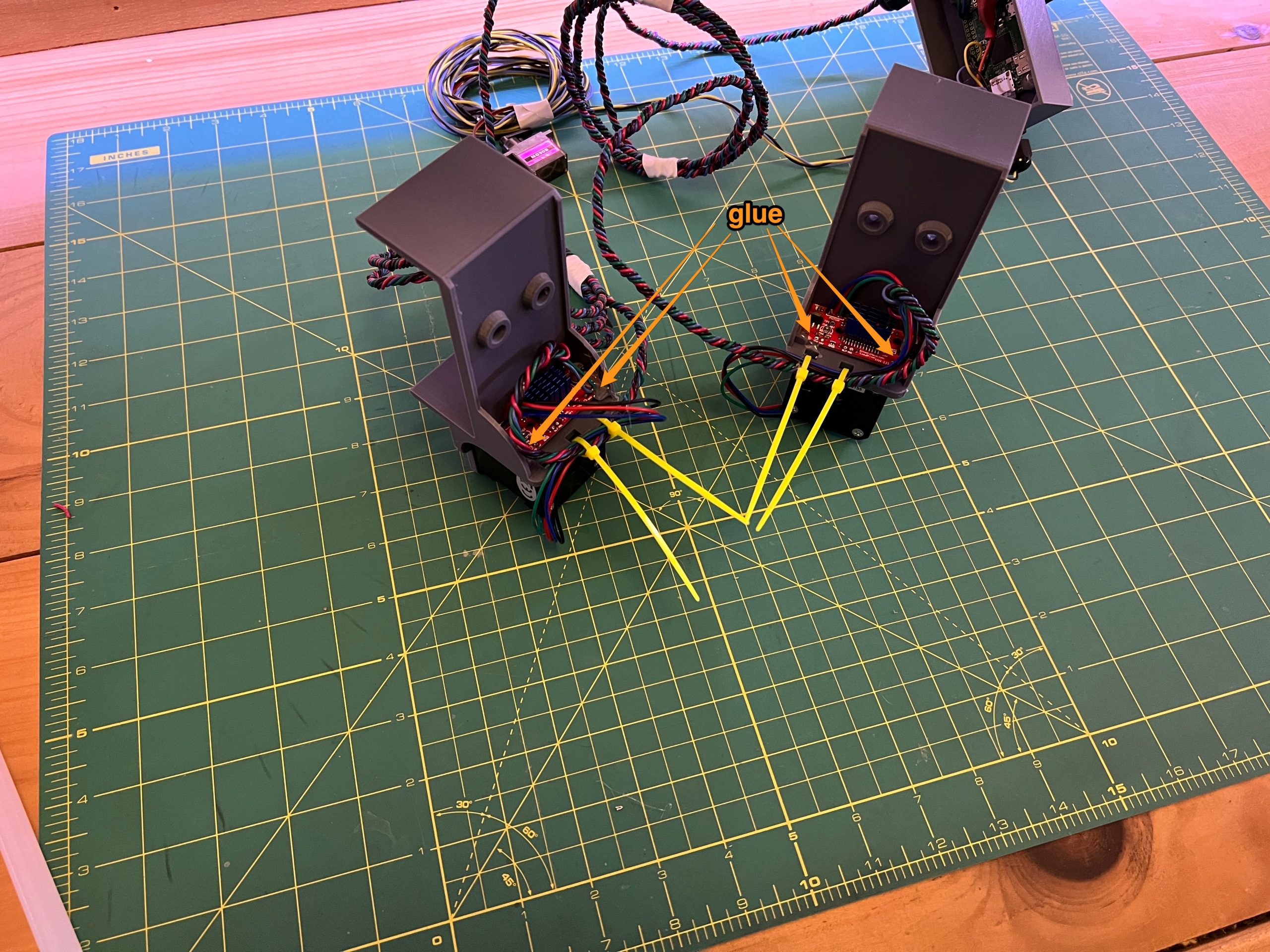
Snip the zip tie extras.
9. Gondola
Parts
3D printed
– gondola_x1
Acquired
– M4x20 thumb screw bolt x1
– M4 hex nut x1
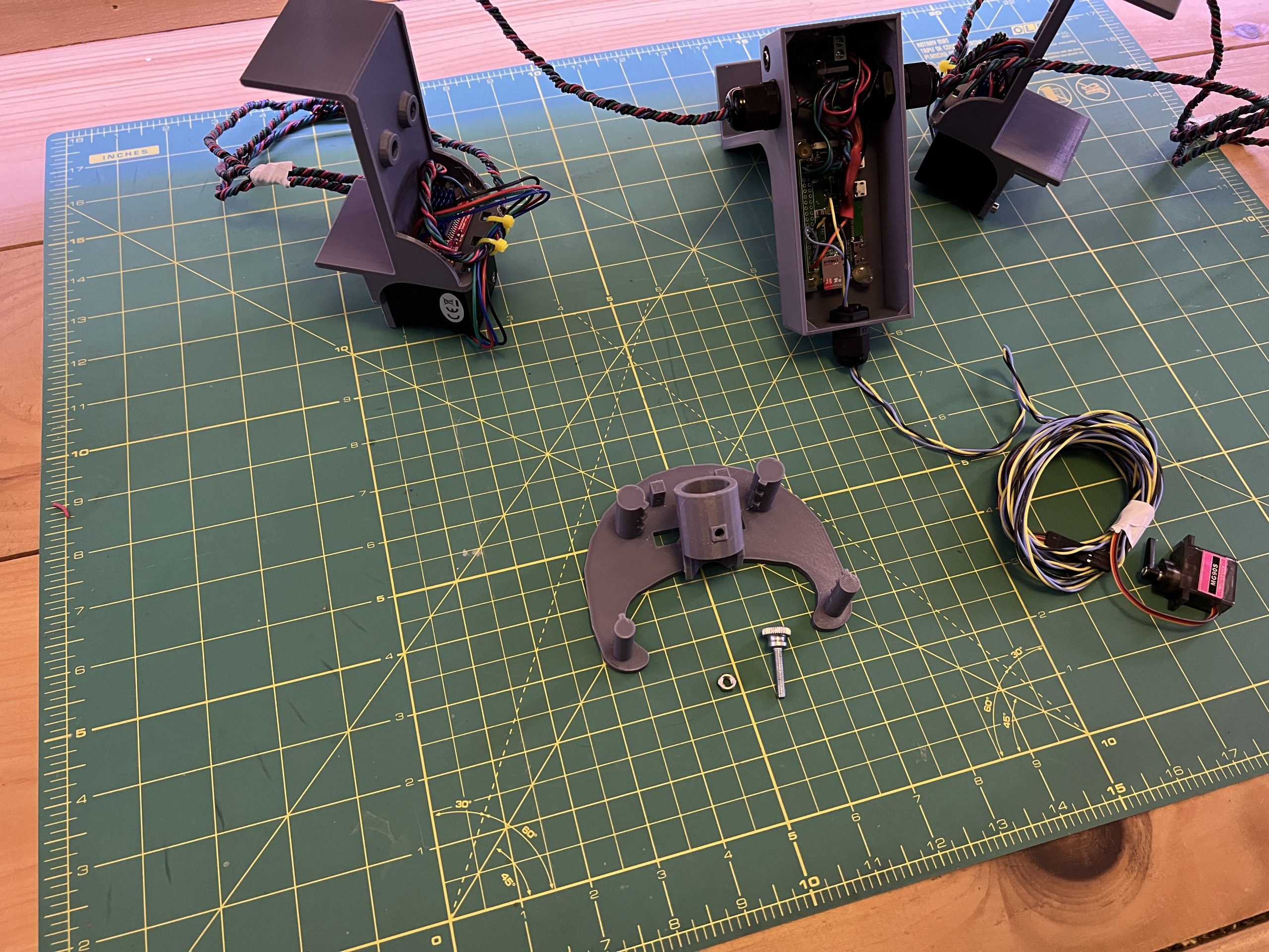
Pressure fit the M4 nut into the hex shaped hole inside the pen holder.
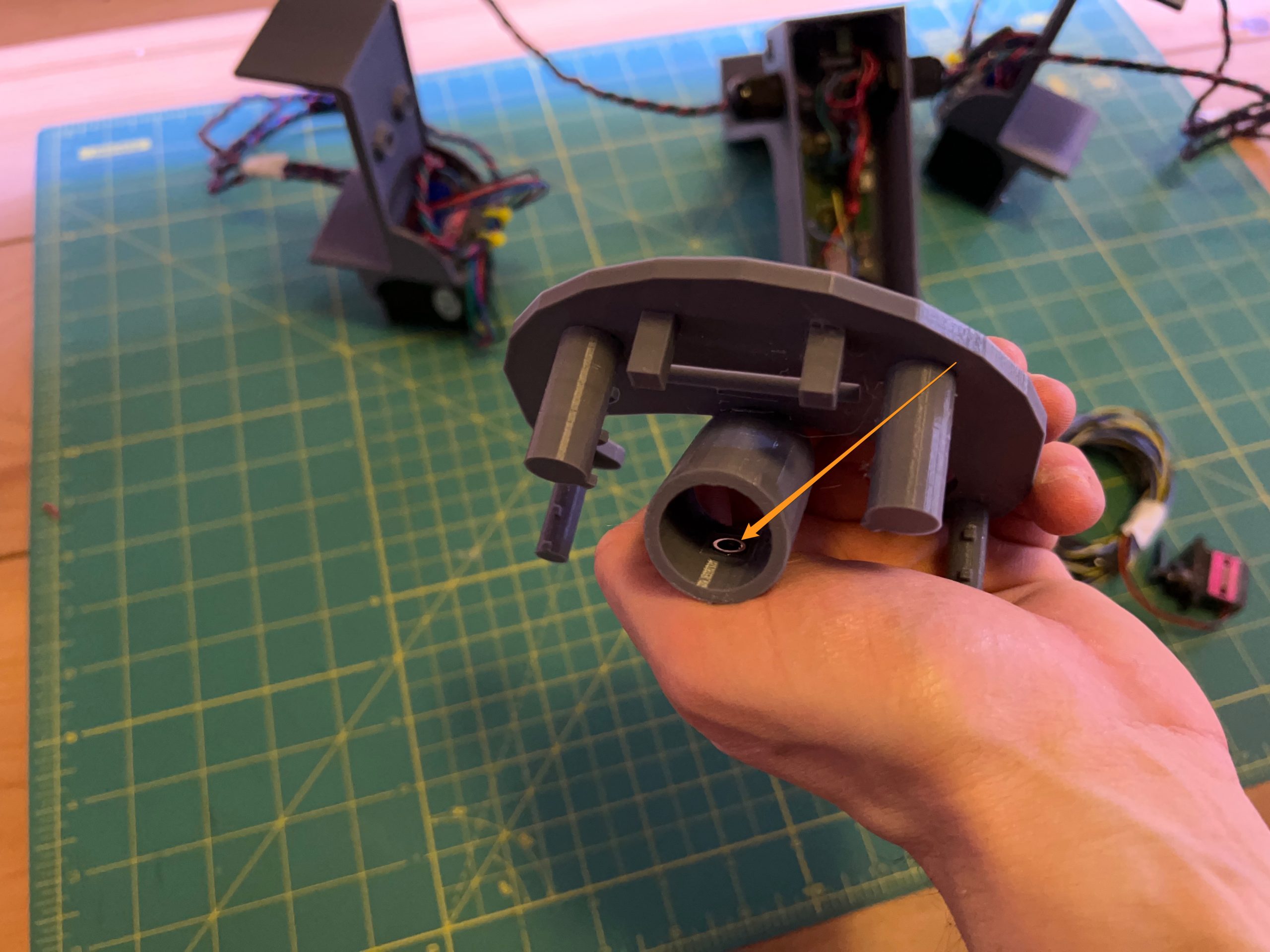
Then screw in the M4 thumb screw bolt.

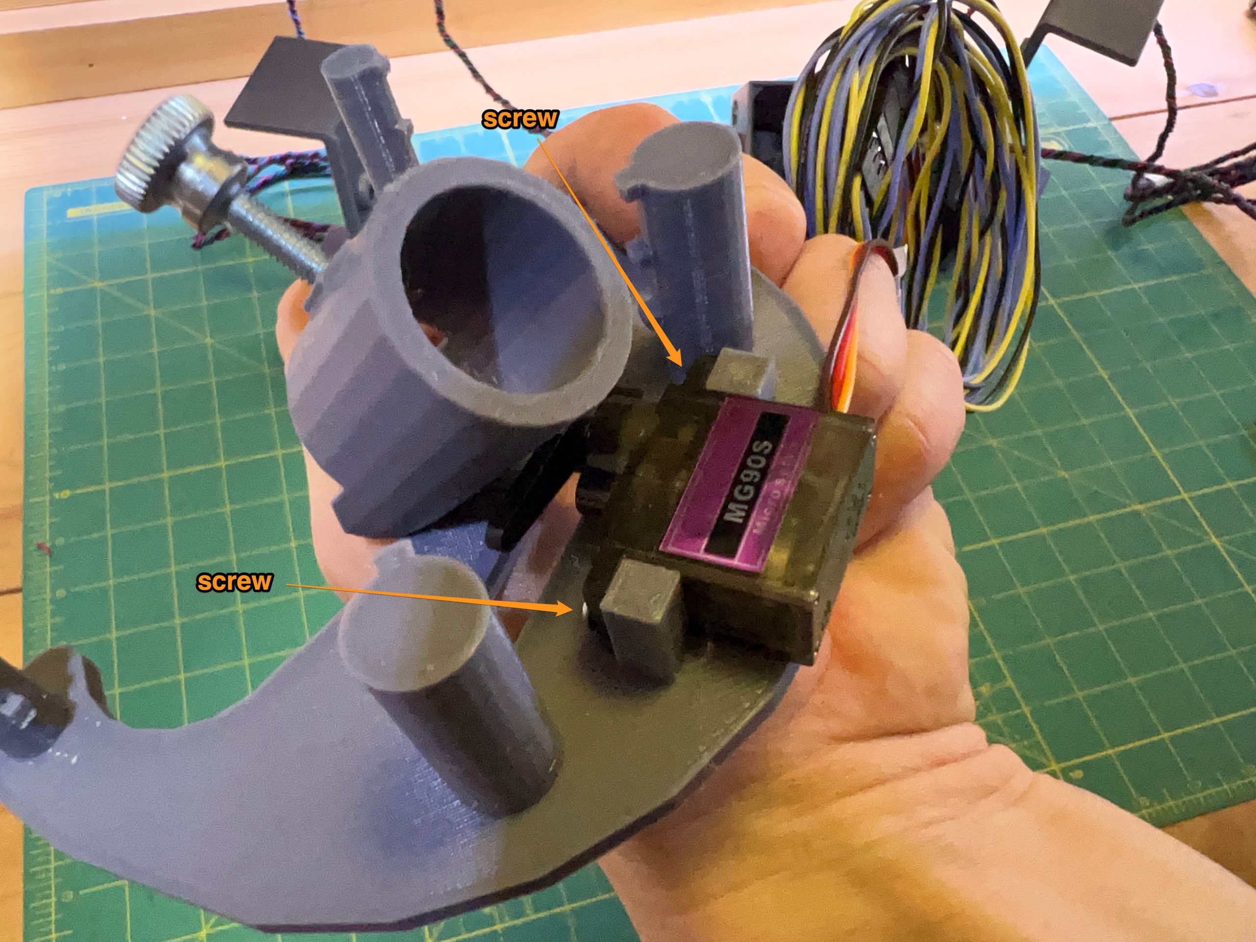
Grab the servo motor and fit in right bellow the pen holder. You shouldn’t have to use any force to get it there, but it is a tight fit that will require some moving around until it goes in. The servo motor comes with 2 little pointy screws that you can use to keep it in place on the gondola.
To be thorough, you can power the circuit and test the pen up and down functions again. The whole gondola should be flush against the table in the pen down position, and pushed away from the table in the pen up position. There’s a good chance you’ll need to re-adjust the servo’s arm to optimize the up & down positions.
10. Stepper Motor Pulleys
Parts
Acquired
– gt2 pulley x2
Grab each pulley, and take note of the 2 hex nuts they each have. You want one of the hex nuts to not obstruct the shaft hole at all, and the other to slightly come out. Adjust them until it looks something like this:
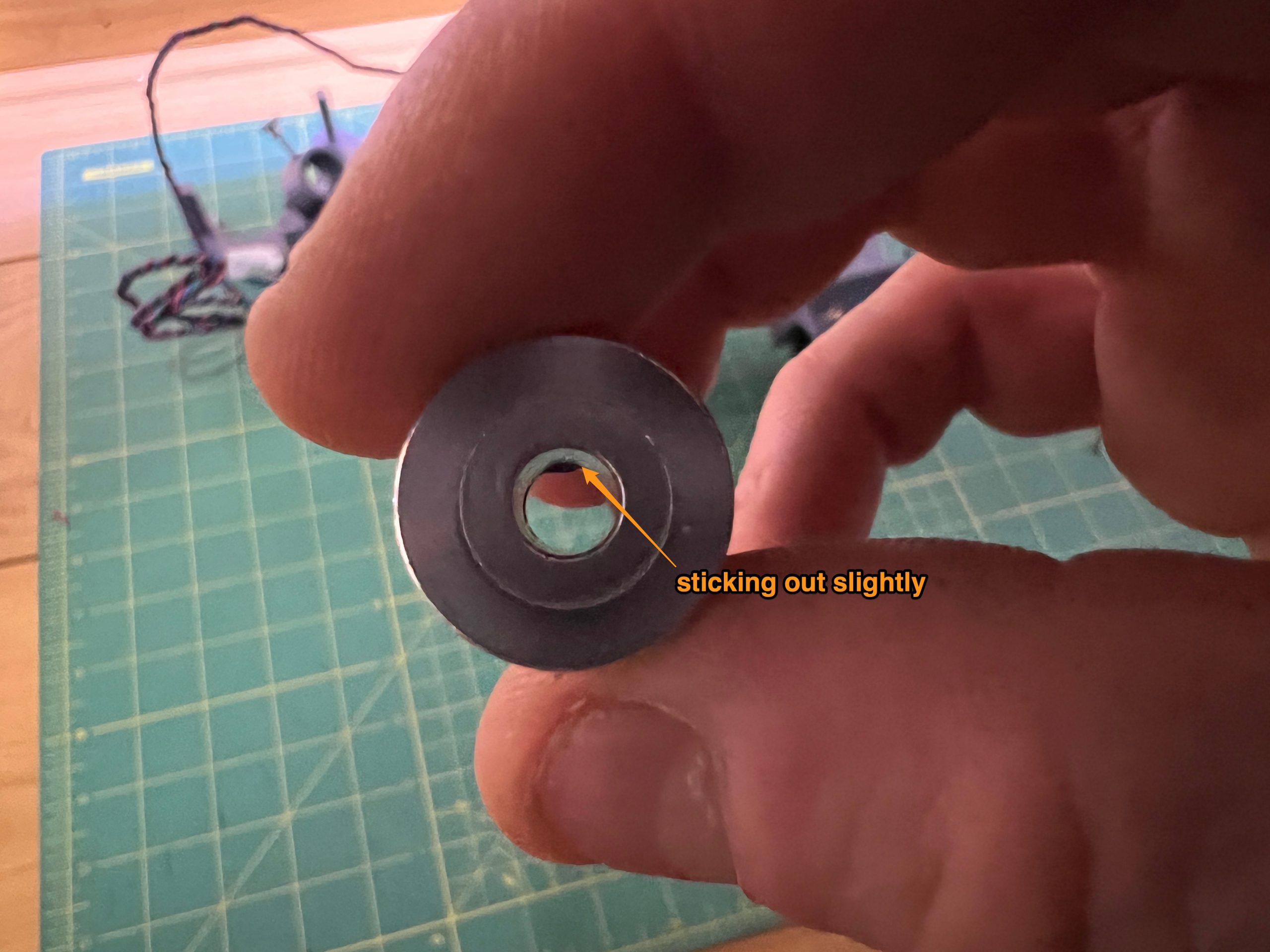
This is because the motor shafts have a flat side, and we and this nut sticking out a bit to line up with it.
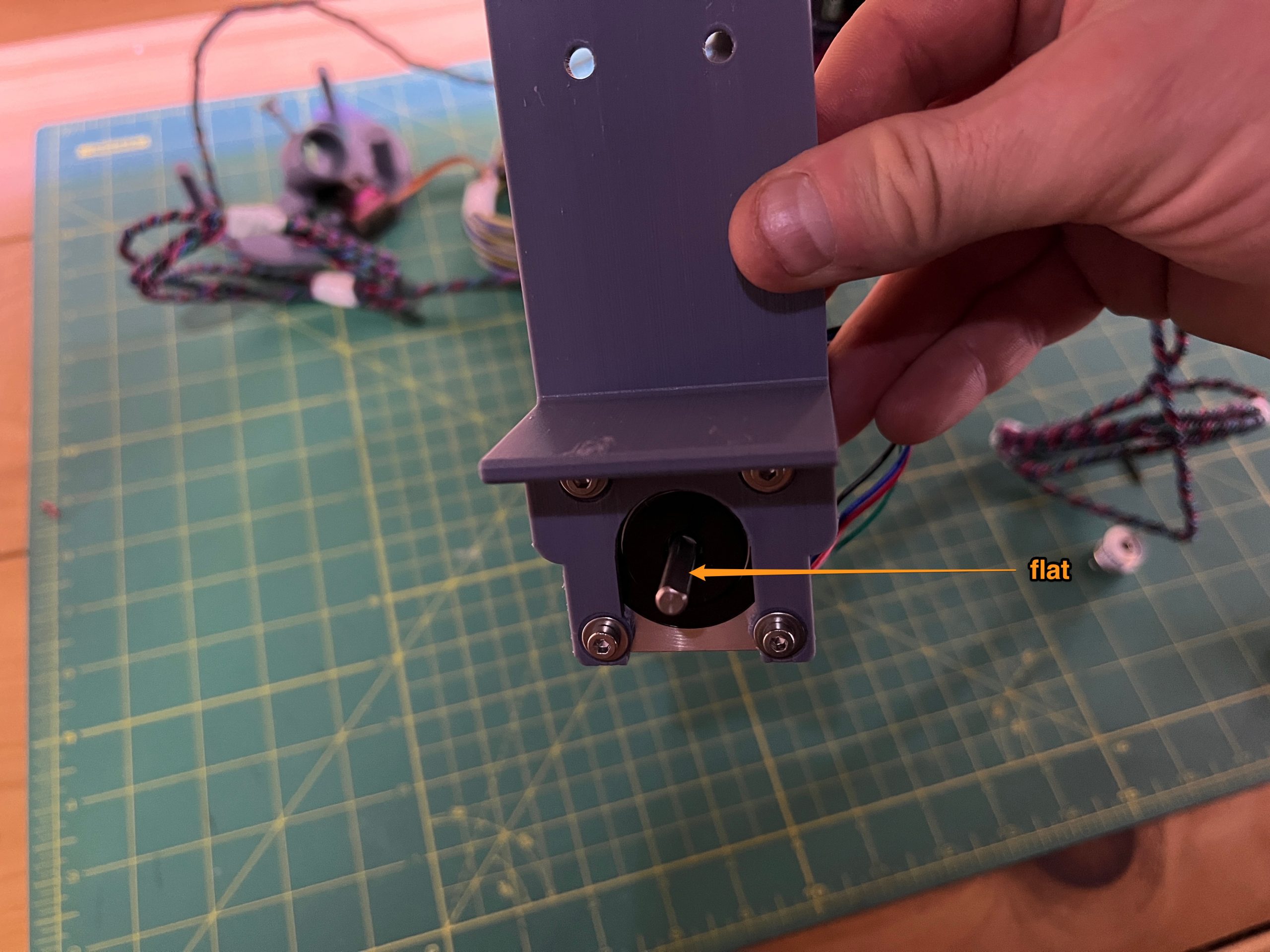
Install the pulleys so that they are flush with the end of the shaft, the belt needs to be as close to the drawing surface as possible, watch their orientation.
11. Logic Box Cover
Parts
3D printed
– logic_box_cover_x1
Simply tack glue it to the logic box with 4 drops of glue in each corner where a small protrusion is ready to receive the glue.
And voila! Your gondola Plotter is ready to go!
Deployment & Calibration
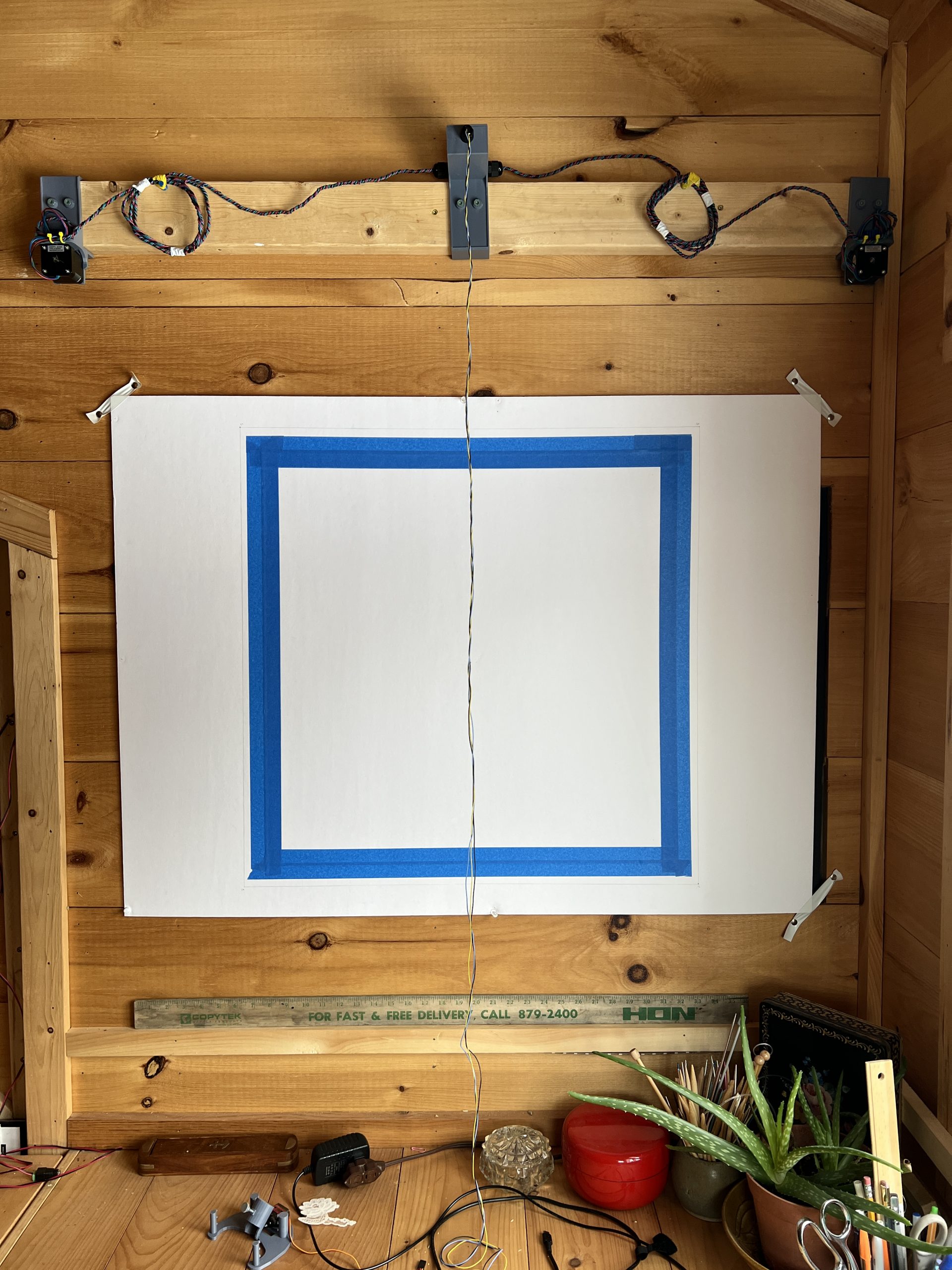
Your plotter is meant to be screw onto a standard 2×4, this way it can be moved and deployed as a unit. If there are no 2x4s in your country, get in touch and we can tweak the model so the mounts fit something else.
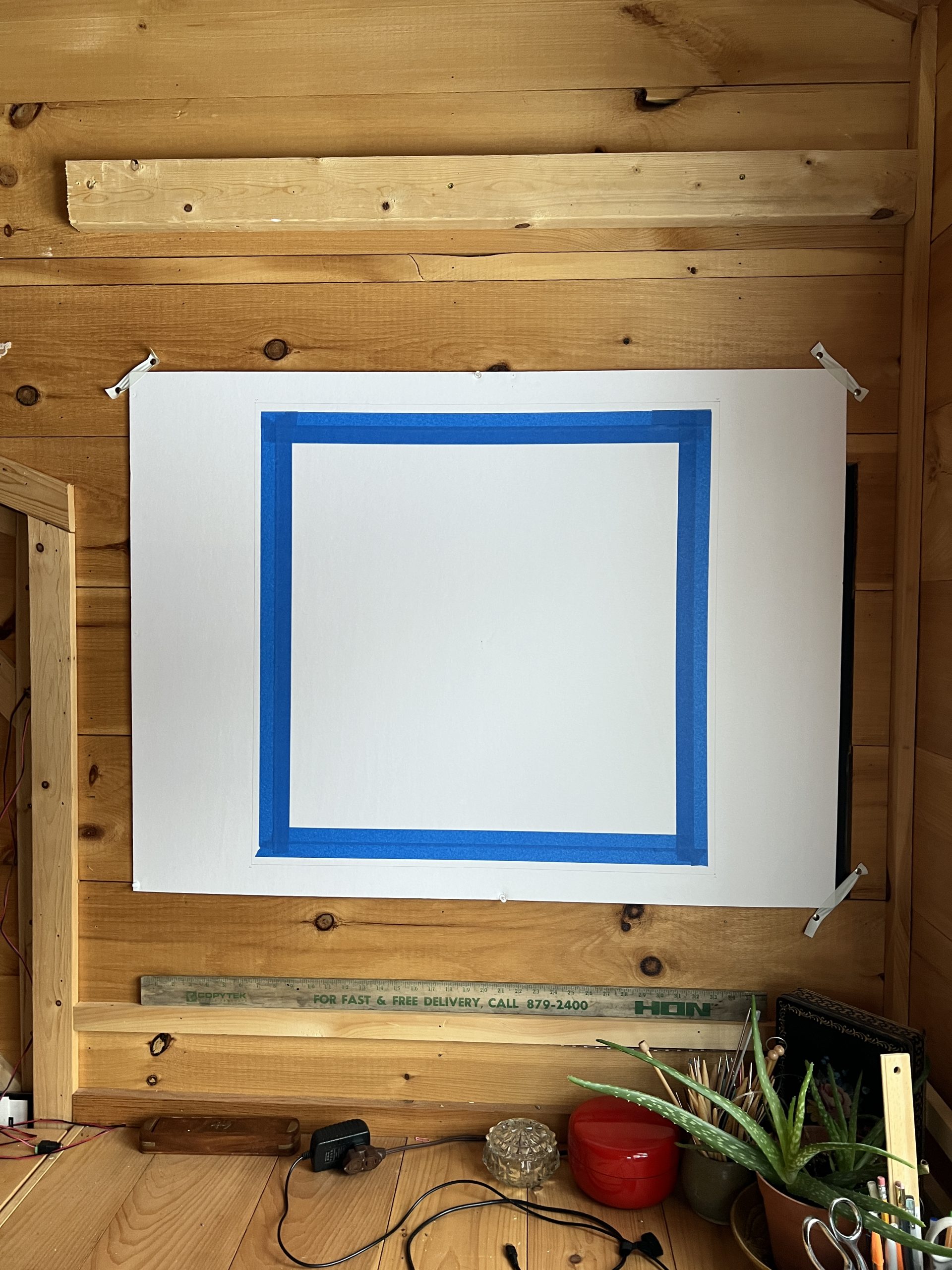
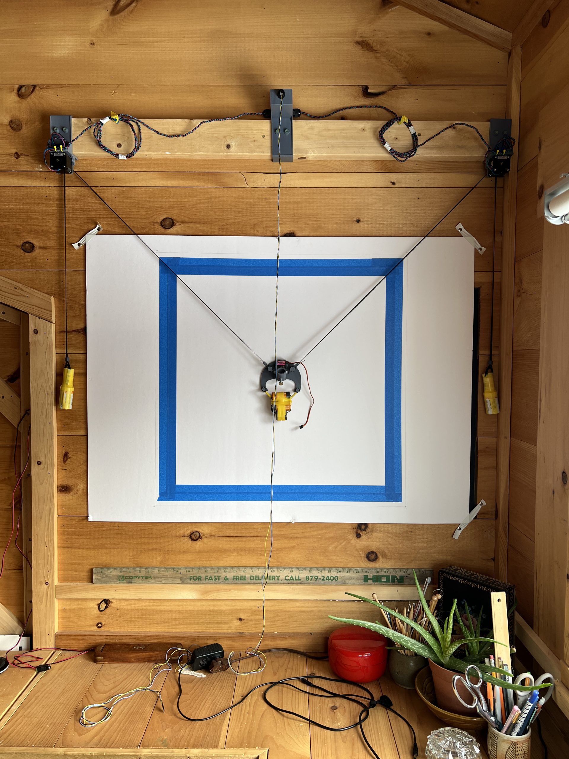
At home I have a 2×4 on a wall with some paper and dimensions pre-marked. But all you need is a vertical surface and the 2×4 attached to it.
Screw your plotter mounts into the 2×4, make it so they don’t move, but don’t put too much pressure on the 3D printed plastic or it’ll break.
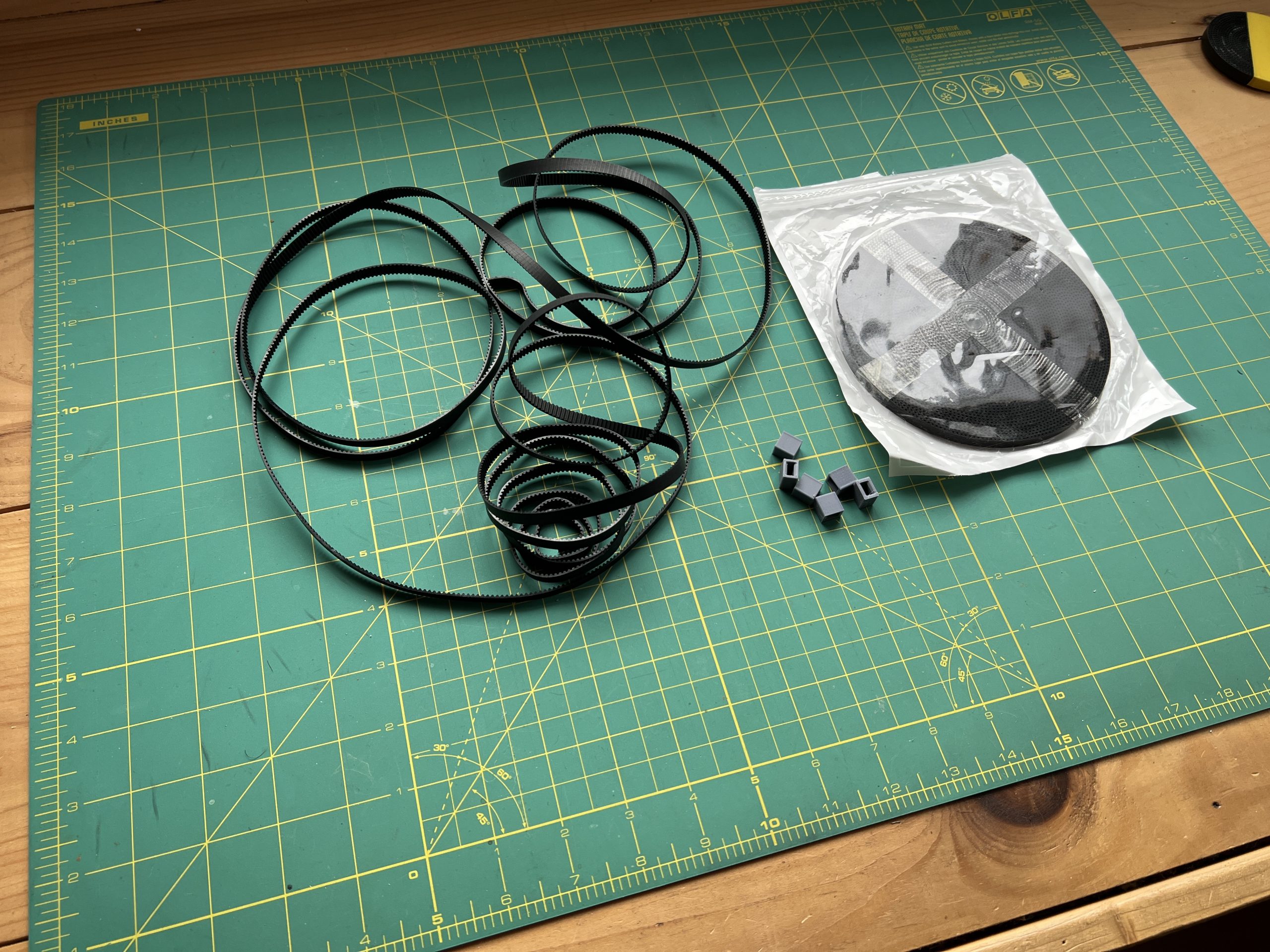
Grab the GT2 belt and 3D printed belt_looper_x6. Cut 2 lengths of belt, you want each length to be as long as the diagonal of your drawing area plus some slack.
Loop then around each stepper motor pulley.

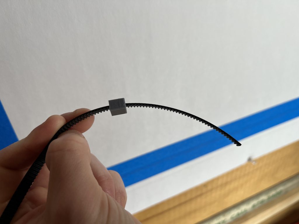
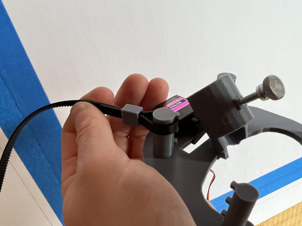
Grab a couple of belt loopers, slide them on each belt, loop the belt on the gondola and slide the looper back so it keep the belt in place.
There are 3 positions the belts can go so you can adjust weight distribution and tightness against the wall. 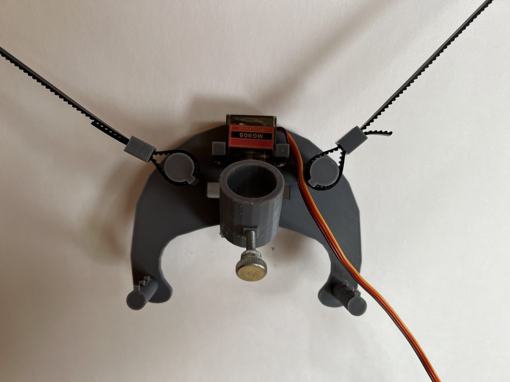
Then using heavy disposable objects and some imagination, create 3 weights to keep the belts straight. Here I’m using some old batteries and some heavy metal nuts. Hang 2 on the other ends of both belts, and one the gondola.
You will most likely have to adjust this, there is no single way to weight these down. Depending on the size of your plotter, the surface friction and weight distribution. Ultimately you want the best to be straight, and the gondola flush against the wall on Pen Down. The rest is adjustable to achieve that in your particular setup.
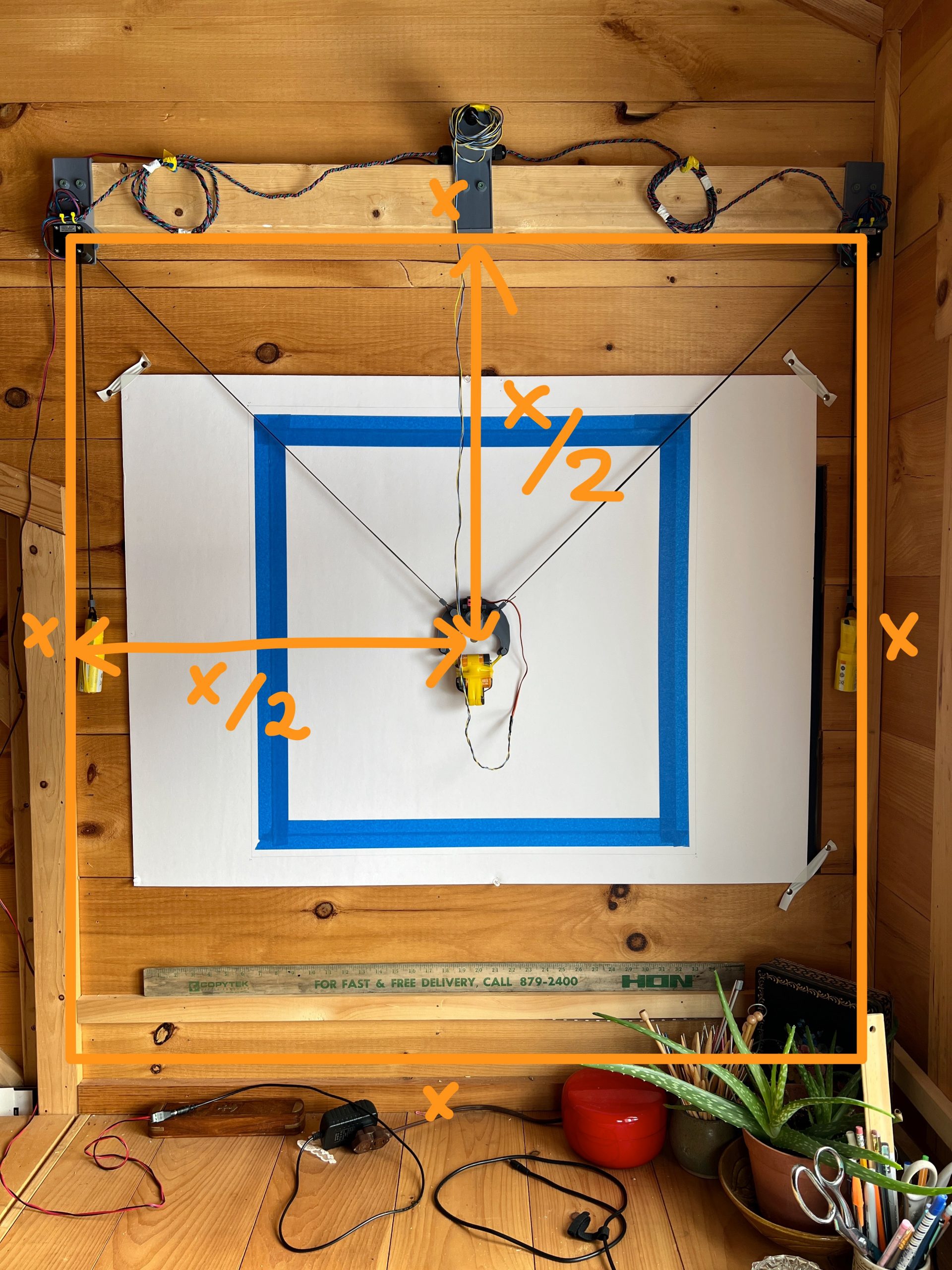
Before you power on the plotter, you need to adjust the belt lengths such that the gondola center (where the pen comes out) is positioned exactly at the center of your drawing surface. Every time you power on your plotter, it assumes it is placed in the center. If it isn’t, nothing will work right. If X is the distance between the shafts of both stepper motors, the center is at X/2 of the edges of the square that is the drawing surface.
I find it useful to make a small indelible mark there so I don’t need to re-measure the center every time. I very carefully measure it once, make a mark, and then I can simply place the pen head at the mark.
Ok let’s power on the plotter. And for it to be able to draw, it needs to be calibrated. The only thing it needs to know for this is the exact distance between the centers of the stepper motors. If you move your plotter still attached to its 2×4, the distance is the same, it will remember it. If you re-deploy it and change that distance though, make sure you re-measure it and punch in the new one when calibrating.
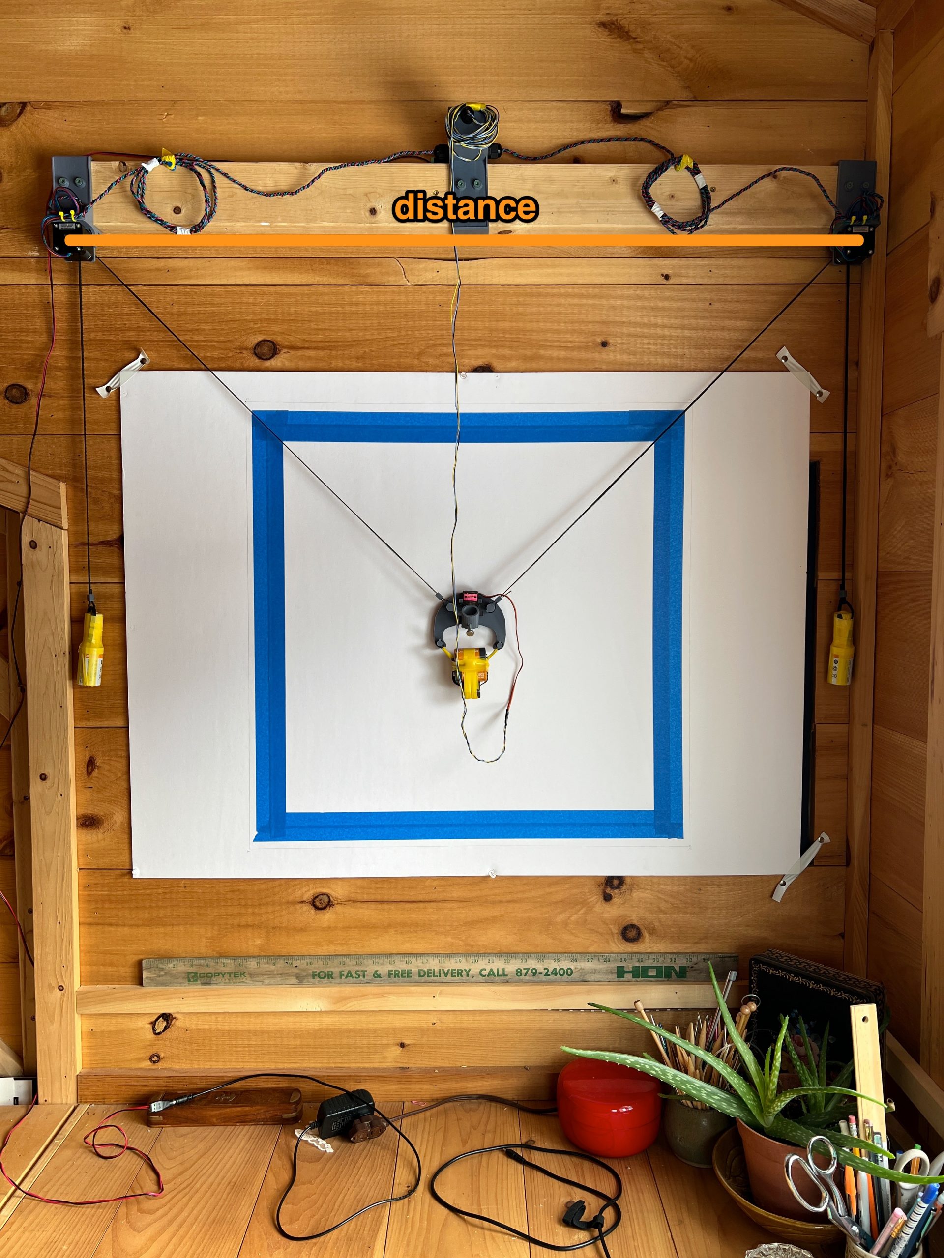
To reiterate, there are 2 things that matter for the plotter to draw accurately:
- that the gondola’s pen tip be placed exactly at the center of the drawing surface
- that the distance between the centers of each motors be accurately measured and entered in for calibration
It is a bit tricky to set everything up and measure accurately at first, but overtime it become quick.
hi ben! i’m just about to wrap up building my gondola bot, and have the parts on order for plottybot (idk im a completionist)
question though — what pens/markers/etc have worked best for you in your testing? does the same type of pen work on the gondolabot as plottybot?
love these projects! thank you so much for the detailed build guides.
Pretty much any pen works on the tabletop plotter, but few work well on the gondola version. There’s barely any pressure against the paper on the gondola one, and the angle to the paper is not adjustable at 45°. You want a pen that starts flowing with little pressure, I find that gel pens tend to work well. My favorites of the moment are the PILOT Precise V5. But others work well too.
Ok Ben… I just finished helping my kids make a PlottyBot Gondola (I soldered and got the fun job of cleaning up the prints). I figured the larger form factor would be more fun for the future and since I assisted someone put together a Maslow CNC a while back, I figured I could get this to work without any tears if we had to troubleshoot.
We fried a Pi in the process ( my daughter said “Ok, lets get a new one.” Ha! I definitely cried tears considering how hard it was to source another one without breaking the bank!) Not definitely sure how I did it but I suspect the way I set up my Dupont connectors may have caused a short. I placed the little windows where you can see the metal in the Dupont connector facing each other for the motor drivers and perhaps the metal on one of my connectors was bulging enough that either the ‘step’ and ‘direction’ or ‘enable’ and ‘step’ crossed? I don’t actually know but all the right pins were connected and it’s the only change I made. I covered the windows with electrical tape on the second take and so far all is working amazingly well on a new Pi Zero W (thanks Rpilocator!).
I can’t thank you enough for putting something like this on the internet. There are a bunch of plotter projects like this on line, but the use of the raspberry pi makes this project so special as it is self contained and runs its own web server. I’m not well versed in Gcode and still trying to get it to draw with something other than the plotter code – reminds me of using Logo on early Apple computers and fun to watch the kids use it.
Is setting ‘home’ an option so it starts writing/plotting from that point?
Is there a way to set the borders of the work piece so the plotter only plots within the borders I set?
I know you are working on user documentation and looking forward to a step-by-step workflow. I’ve read the other posts above and am looking at tutorials now but appreciate the other users who have published their workflow to get images into gcode to get us started. Just got to figure out how to control the size of things…
Thank you for all your work and generosity and sharing for all of your site (my kids want chickens now after looking at your little one enjoying them).
-Best regards
Thank you for the kind words!
I’m not sure what you mean in your first question by “setting home”. But when you power the plotter, it assumes that it’s position is (50,50) right in the middle. After that it keeps track of where it’s at on its own.
To set the borders, you can play with the gondola_reserve_margin tunable in the Mechanics section at the very bottom. I believe it’s set to 20% by default, that is to avoid extreme position where the gondola isn’t accurate. But you can always adjust it to defined a smaller canvas. You could write some quick PCode that goes through (0,0) -> (0, 100) -> (100, 100) -> (100, 0) to get a real world representation of what your drawing area is with the adjusted margin.
Another way is to simply give the plotter code that doesn’t expand the full 0->100 range.
As for getting your hands on some GCode, the easiest way is to use Inkscape to convert SVGs (and that’s still a bit complicated :)). This is where the real artistry of these machine lies, in all the methods, programs, and processes you figure out to turn something into GCode.
Of course you can also use the plotter with its others mode that don’t rely on GCode, but GCode opens quite a few doors for cool algorithms you can find.
Here’s a sheep for your kids 🙂 https://ben.akrin.com/downloads/sheep.gcode
Hi!
i would love to build this with kids. However, the Pi image (gondola_plottybot_2023-01-31.img) is not downloading. Is it still available? Is there another link available?
Thanks!
Brian,
odd! It’s downloading for me. The full link is: http://ben.akrin.com/downloads/gondola_plottybot_2023-01-31.img
Do you get any sort of error?
Hi,
Very nice Project!
I recently build a Polargraph with cheap 28byj-48 steppers with uln2003 drivers.
(https://www.google.com/amp/s/www.instructables.com/25-Recycled-Polargraph/%3famp_page=true)
Would it be possible to use this setup with your Raspberry image?
Thanks a lot!
Flo
These are simple machines, but the motors I used are stepped differently so you’d need to at least update the code. https://ben.akrin.com/driving-a-28byj-48-stepper-motor-uln2003-driver-with-a-raspberry-pi/ might help to that effect. Everything else functions the same.
Thank you for your answer!
I will try it out
Meanwhile i found another interesting build:
https://www.thingiverse.com/thing:4192091
A multicolor gondola for vertical plotters. Hardware seams fine, but software is missing..
Hello Ben,
i found out that you can use the 28byj-48 steppers without modification on the easydriver board.
(you even don´t need the bipolar mod)
i just need to find the right varible to change the steps per revolution.
Nema 17 is somthing like 200 or 400 (Half or Full Step)
the 28 byj-48 Steppers is usually someting like 2048 or 4096.
Can you tell me where to change these settings or where i can find this settings.
SSH to the Pi works, but i don´t know where your python script is locatet to change it myself…
thanks a lot!
Flo
Hey Florian,
take a look at the variable called: gondola_steps_per_cm in /usr/local/bin/plottybot.py. It doesn’t define steps per revolution, maybe your pulley’s different too. So what you can do it run the motor for a known number of steps with the belt attached, and divide that number of steps by the length the belt traveled.
That’s how I skinned that particular cat. I hope this helps.
Thank you! I found the variable and changed it. It works now.
I have another question: In my setup, the motors have pulleys that wind up some wire (no counterweight, this is my setup: https://www.printables.com/de/model/253295-walldraw-wall-plotter-polargraph)
Is it possible to add some buttons on the webpage to manually drive the motors? Maybe some text input for number of steps (+ and -)
Because the wire is wound up on the pulley, this would be very easy to navigate the gondola to the home point…
Thank you
Maybe at some point but it’s not on the map currently, sorry but the honest answer is that you’re on your own having steered off the beaten path :). I’ll point out that a timed belt is more accurate than a spool. And while I love the 28byj-48 motors, I even used some for my first iterations of PlottyBot, they are just not robust enough and will inevitably fail on the large drawings these machines render.
Hi Ben,
Thanks for your answer and thanks for the Stl files!
I will try it myself.
I just used the 28byj motors because i want to build a cheap an simple machine for some kids workshops.
I watched different plotters and liked yours most, because of the inbuilt webserver and the possibility to use it without a Computer (unlike many other variations of wall plotters)
Let me know if you or somebody else is interested in my progress, then i will post about it.
Greetings Flo
If you’re interested, here the STL for the 28byj-48 holder I built when I was using them:
https://ben.akrin.com/downloads/28byj48_holder.stl
https://ben.akrin.com/downloads/28byj48_holder.jpg
Hey Ben! I just finished your design. The simplicity of the components has been a great STEM lesson with my daughter. I’m unfortunately having an issue with the left stepper. Despite checking connections, replacing the controller and even replacing the wires, I can’t seem to get it to respond. Everything else is functioning well 🙂
I was thinking dead driver as that’s pretty common but if you’ve replaced that already. If you swap the motor itself, does the problem follow the motor or the logic? Should be an easy test too since most stepper motors have a plug.
It’s also possible you have a fried pin on your Pi, although that’s pretty rare I’ve seen it. Did you solder the wires or use Dupont connectors?
Thanks for the reply, Ben. I did swap the motor and have used 2 Pi’s. I’m using Dupont connectors to connect the Pi and the drivers. It seems as if the logic is the issue. In all setups, I can hear the stepper making faint sounds during the tests. I thought perhaps it was a power issue, but the other stepper works as expected.
You’ve replaced the logic, the driver, the stepper and it’s still hapening? 🙂
I hate to state the obvious, but you’re 100% certain you’ve hit the right pins on the Pi? If you swap all the pins between the 2 motors on the Pi, does the problem follow the motor or the pin?
Did you change some of the values in the “mechanics” section at the bottom of the webpage?
Hey Ben… Success! After dismantling, reassembling and reformatting the SD card, I still had issues. I then used a different SD card, and voila! What’s strange is that the corrupt card booted and apparently sent some commands accurately :/ Anyway, Thanks so much for the help! Excited to play!
I have seen bad SD cards result in the oddest way possible, but that it really really bizarre. I will say that I’ve only exclusively “pro” or “high” endurance SD cards lately and they are much less prone to failure. In fact I haven’t had one fail. Flash memory behaves in the weirdest ways when it fails, their extra cost is well worth the saved headaches. I’m glad you figured it out :).
Hi CJ i’ve ran into the same problem as you have with only hearing a faint Stepper Motor noise coming from the (Right side) when trying the Test Top Stepper Motor. I have tried 3 of the 5pcs KOOBOOK A3967 EasyDrivers, and have tried another Stepper Motor and made sure wiring was all correct. I first flashed a Sandusky EDGE 8GB and then flashed a Samsung EVO 64GB. My question is which SD card did you use. Thank you.
Hi Steven,
I find it really hard to believe that the SD card is the culprit. There are lots of failure modes with stepper motors that will result in them humming without moving. It’s good to know you’ve eliminated the driver by trying other ones. Does your left side motor work? How easy would it be to swap with that one to see if the problem follows the motor, or the pins on the Pi?
Thank you for replying so fast Ben and thank you for this project. Yes the left side motor works fine, I will swap out the left motor tomorrow and let you know what happens. Thanks Ben
Hi Ben, it turns out it was a simple wiring mistake the right motor is now working fine I don’t know how I missed it. I will calibrate it tonight thank you Ben.
I’m glad it was simple. Checking wiring it’s like proofreading, if your eyes didn’t catch a mistake the fist time, they’ll miss it the next 10 times as well.
Hello again Ben, I have everything setup and imputed the distance for the calibration, I first tried the Draw section but couldn’t get anything to draw ( I was using an iPad ) I the tried the handwriting section with the live tab checked ( I believe that’s what it’s called ) but there was no response from the motors or pen. I then went to the Mechanics section and tried Pen Up , and Pen Down which both responded. I also got this Error code below. Is there anything offhand Yo can think of that may be the problem besides of course the Error code which I will try to look into with my limited knowledge of coding.
• Error
Exception in thread Thread-4: Traceback (most recent call last): File “/us/lib/python3.9/threading py”, line 954, in _bootstrap_inner self.run() File
“/us/lib/python3.9/threading py”, line 892, in run self. _target(*self._args, **self. _kwargs) File
“/us/local/bin/plottybot.py”, line 2431, in ht_penstrokes_processing while ht_penstrokes_mutex==True: UnboundLocalError: local variable ‘ht_penstrokes_mutex referenced before assignment
It looks like I may have a bug 🙂
I’ll look into it, but in the meantime, you should be able to use the handwriting stuff without the “live” checkbox. It should render in the draw box up top, and you can hit the “play” button to have the machine draw it. And you probably need to reboot the Pi to relaunch the Python process.
I’ll let you know what I find, thanks for the report and sorry about the bug.
Hi Ben, how are you doing? I just wanted to let you know where I am in the process. I do not get the error message I sent last night and I did get the gondola to try to draw out a letter, it was actually the fifth letter that i wrote in the Handwriting / Typewriting section. I believe there may be some sort of communication issue between my inputs from the iPad to the Pi and vise versa. I have used these Pi’s before and SSH to them but Putty which I use for SSH can not find the Pi, I also use Angry IP Scanner and Find My Pi but neither one can find it. I also log into my router and do not see PlottyBot. I’m not sure but is it possible that i need to make the Pi use a static IP address as I have done with other Raspberry Pi’s. I will continue to figure out what I am doing wrong. Thank you again Ben for all your help.
It does look like I have a bug, I forgot to declare ht_penstrokes_mutex in that function the error references (ht_penstrokes_processing).
Since you’re SSH’d in, it might be quickest to just edit the Python, find that function (ht_penstrokes_processing) and add the variable ht_penstrokes_mutex to the list of globals defined at the very top of that function.
This omission is bizarre, seems like my tests should have failed too.
As for the networking, Plottybot does something weird in spanning its own AP unless you connect it to your local network. This mechanism works well here at home but it’s just one guy testing on a few network setups so it’s entirely possible there’s an interaction with your home network that doesn’t work well. Maybe you can leave it not connected to your home setup and test by connecting to the “PlottyBot” network it spans. That would remove some variables.
I hope this helps, I’ll endeavor to fix this variable in the code. Sorry you ran into that bug.
Hello Ben,
I hope you are doing well, I will try all of that tonight.
Thank you Ben
Hi Ben,
I believe I did not make myself clear in my previous post on December 10th, but I can not connect to the Raspberry Pi Zero W through ssh no matter what i try. I have checked off the option to add SSH and also added my Wifi ssid and psswd information within the Raspberry Pi Imager. I also skipped those options in the imager and added manually the the blank ssh file and the wpa_supplicant.conf in the boot folder after the image is finished being created just to see if that would make a difference. Also when I do get access to the Plottybot webpage do i have to choose a wifi network from the Wifi Setup window in the top right corner? and I do get the same error code maybe 50% of the time and besides that I just think its some kind of connection issue, I see the connection on my iPhone or iPad going from No Internet Connection to connected every minute or so. I realize these errors can be difficult to resolve so if you do not have the time I completely understand.
Thanks Ben I appreciate it
Hey Steven,
I don’t know how the PlottyBot image interacts with the ability Raspios has to load network information on the boot partition, but I’m guessing poorly :). I’d definitely re-write that SD card without your wifi preloaded.
Then I’d boot up the Pi, give it a good 10 minutes as it installs a bunch of stuff initially. And it’ll span its own wifi network called “PlottyBot”. You can connect to that. The one thing that kind of sucks when you’re connected to it this way, it that it has no internet connectivity and neither does your iPad. They’re just in their own little network that’s not on the internet. But you can still use the machine and have it draw just fine. Optionally, you don’t have to but it makes life a little easier, you can indeed have it scan for wifi network and connect to that. When you do that PlottyBot will remember that network next time it boots up and connect to it. But if you took it somewhere else not in range, it would revert back to spanning its own network so you can always use it.
This “connect if you can or span your own wifi” mechanism is very involved and intricate. And it likely doesn’t play well with the boot partition preload.
So I think starting fresh on that SD card is your next best step. I hope this helps :). Take care.
I am confused a bit about the stepper driver. I wired everything up and the stepper motor immediately starts to stutter/turn very haltingly by itself. As if it does not get enough current? I didn’t even activate anything in PlottyBot yet. Do I have to adjust the current wheel on the stepper driver? I read somewhere that the driver is only capable of 750ma? Or do I have faulty soldering?
That does really sound like bad wiring or a bad driver. I’d look at the ground in particular but it’s hard to say for certain.
I think I found the issues:
* I twisted the cables as suggested. That seemed to improve it a little bit.
* I turned up the potentiometer to increase the current. I have a Nema 17 with 1.5A.
* I had the Raspberry hooked up to a charger. I changed that to the official power supply from Raspberry.
The stuttering is as good as gone. It rarely misses a step now. I still have to see if there is enough power.
I’m not sure how closely you followed the circuit diagram, but it’s essential that these things all be grounded to the same ground. You shouldn’t use another power supply for the Pi as it implies it’s on a different ground. That would definitely explain it. I pointed to this stepper driver as I found it to have a good default position for the potentiometer, tuning it can be tricky. And yes twisting the wires is a way to avoid interferences that would result in erratic stepping. But really the ground is first and foremost here, the components all need to share it. I hope this helps.
Thank you for taking time to explain this in more detail, I appreciate it. I did not know about the shared ground, good to know. If I use two separate power supplies, but they are both plugged into the same power strip, would everything share the same ground? Or does it have to be one shared power supply?
This is getting to be beyond my realm of expertise, but depending on your power supplies it might be ok, or not :). If both your power supplies are truly grounded and on the same power supply, I think they indeed share the same ground. But it’s also possible they each provide a floating ground that is different from each other and that will definitely mess things up.
The best way to be sure is to have just one power supply and share its one ground to all components downstream.
I installed everything and it is working perfectly. The two separate power supplies seem to work. Thank you for your kind support!
Nice, thank you for the update :). Do you mind sharing what the solution was? I always love receiving pics of people builds too :).
I just use two separate power supplies plugged into the same power strip. I think spreading the wiring apart helped also a bit to get rid of unwanted signals. Next time I might look for shielded wires. My setup still needs some more work because the pen is hanging below center and not all components are attached firmly. I also used wood for the parts because I do not have a 3d printer at hand. I was not looking for the perfect build, but I just wanted to see this cool machine in action. 🙂
Here are two photos of the still unfinished build:
https://my.hidrive.com/share/3k8sqsboii#$/