Robotics 2025
Dirt Simple Circuit
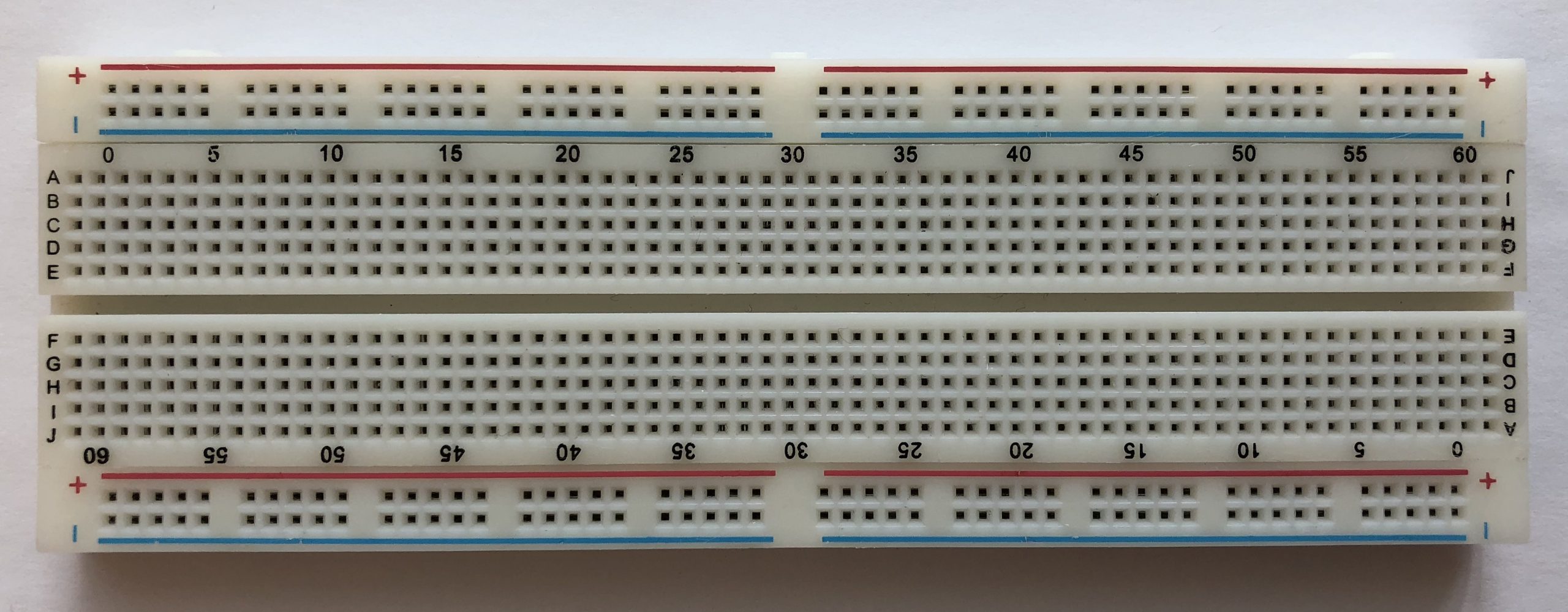
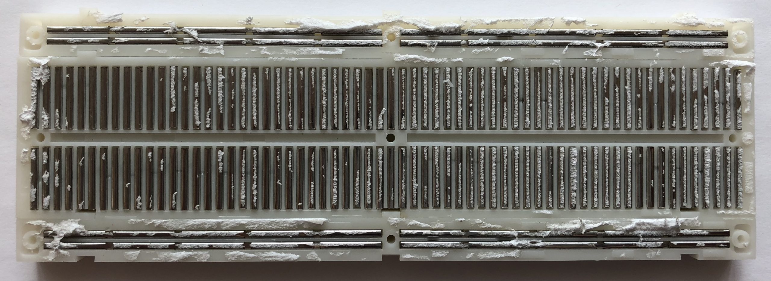
The Breadboard
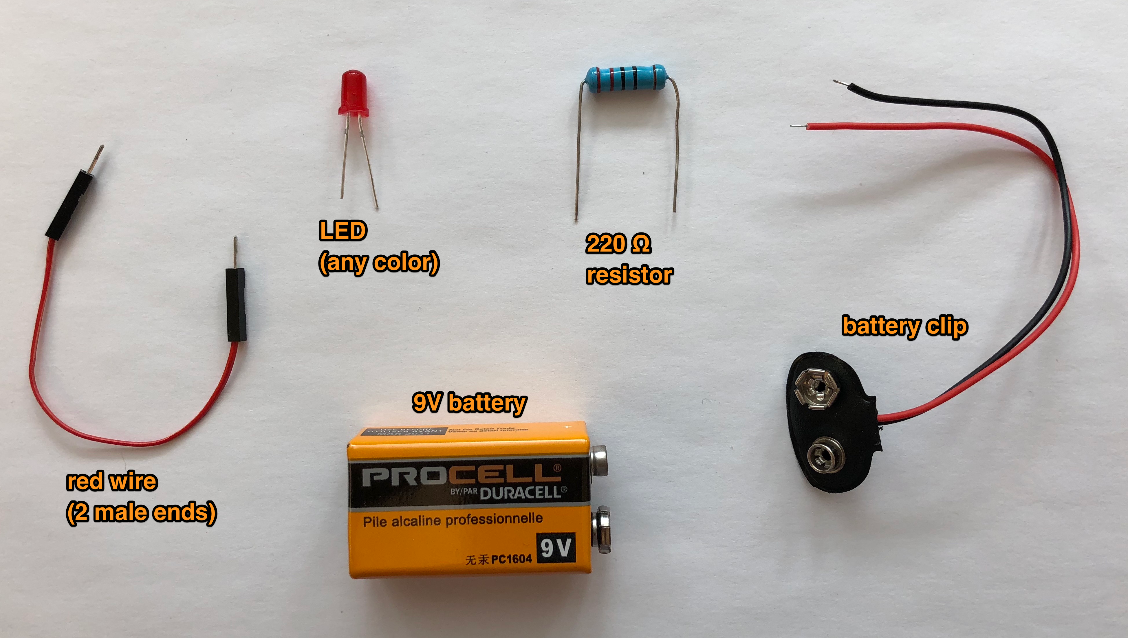
Grab Stuff
Wiring
Power first
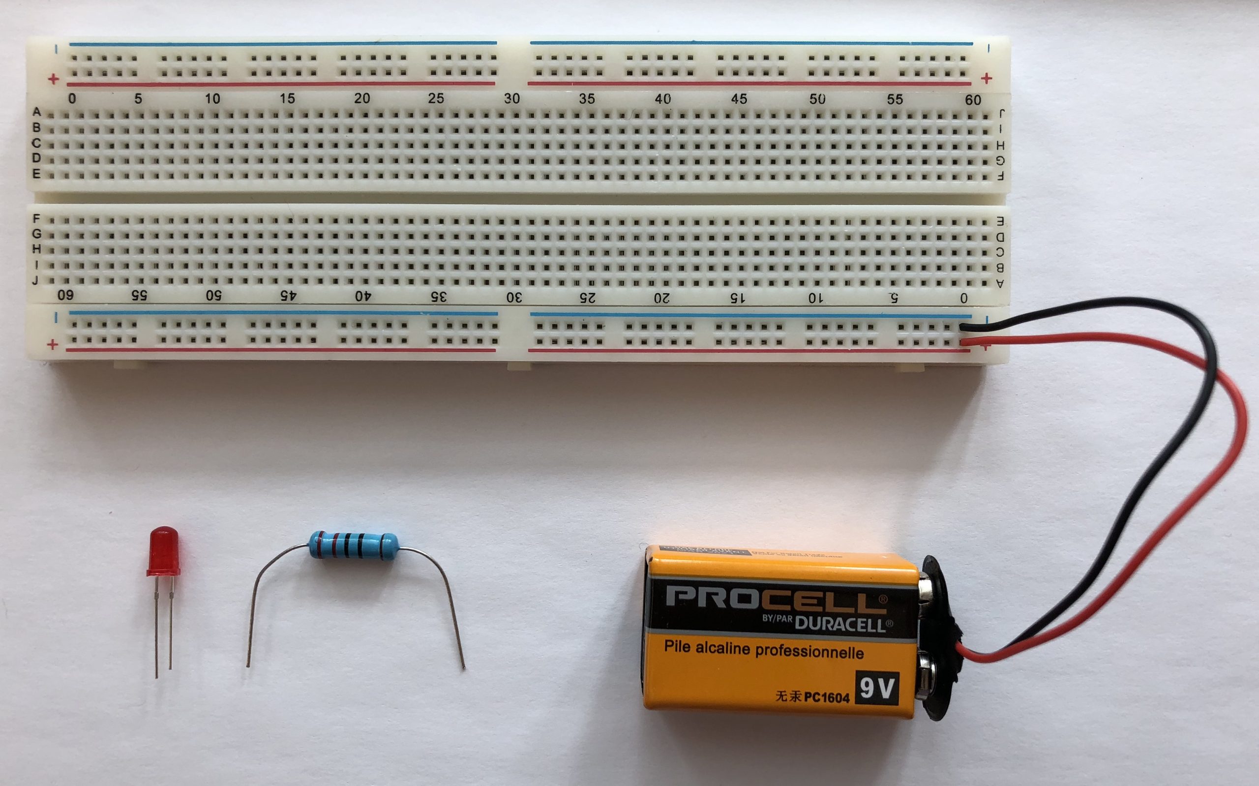
Then the components
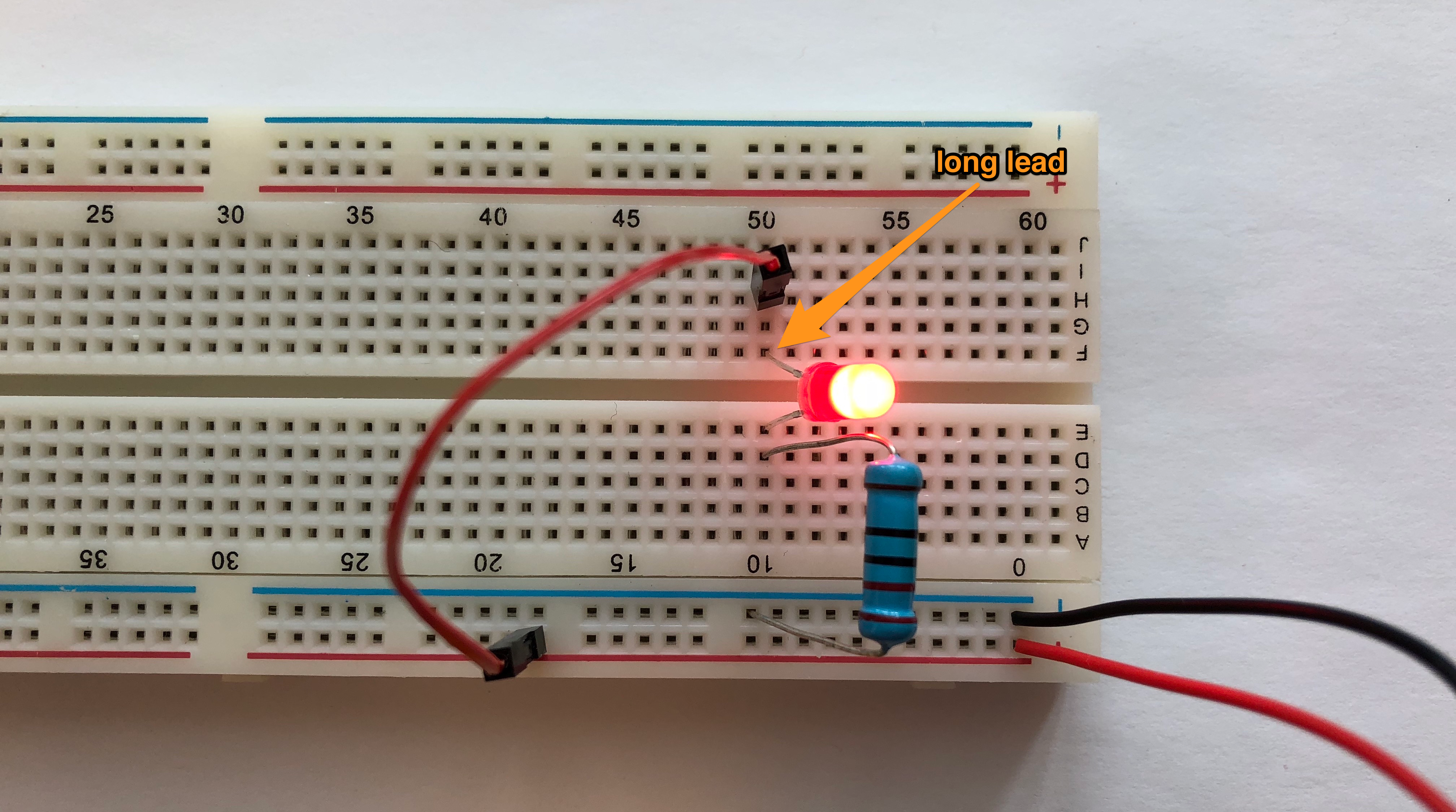
How electrons flow

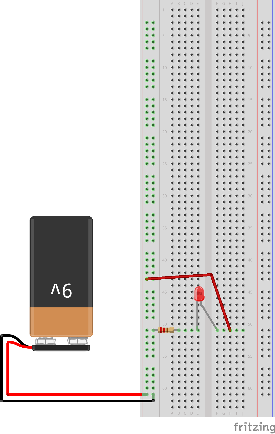
Fritzing
A cleaner and standardized way of representing circuits. Also what we’ll use from now on.
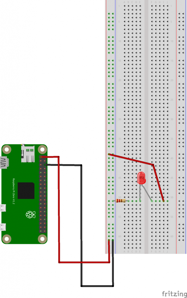
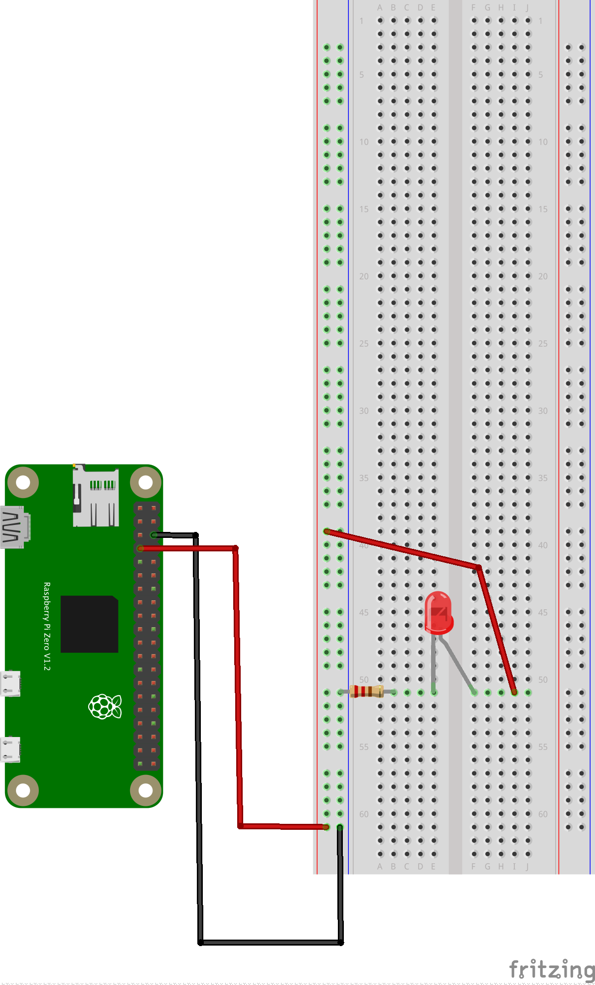
Raspberry Pi
We’ll use model Zero 2 W, please grab one and turn it on.

It’s just a tiny computer. Question on components?
GPIO Pins
Power From the Pins
Coding with Python

Hello World!
Let’s run our very first Python code
print( "Hello World!" )Variables
my_variable = "Hello World!"
print( my_variable )
Operating on Variables
my_variable = "Hello World!"
print( my_variable )

# string replace
my_variable = my_variable.replace( "World", "Universe" )
print( my_variable )

# convert to upper case
my_variable = my_variable.upper()
print( my_variable )

# substring
my_variable = my_variable[0:5]
print( my_variable )

# string concatenation
another_variable = "Blobfish"
print( my_variable + " " + another_variable + "!" )
Numbers
# this is an integer
counter = 5
counter = counter + 15
print( counter )

# this is a float
fine_counter = 20.0
fine_counter = fine_counter / 17
print( fine_counter )
Printing Numbers
# this is an integer
counter = 5
counter = counter + 15
print( "the current value of counter is: " + counter )

# this is a float
fine_counter = 20.0
fine_counter = fine_counter / 17
print( "the current value of fine_counter is: " + fine_counter )
What’s wrong with this code?
Loops
Take a good look at the indentation.
print( "before the loop" )

for counter in range( 0, 10 ):
	print( "inside the loop, counter value is: " + str(counter) )

print( "outside the loop" )
What does the “range( 0, 10 )” function return?
Conditions
for counter in range( 0, 10 ):
	print( "counter value is: " + str(counter) )
	if (counter % 2) == 0:
    	    print( "  which is an even number!" )
How would you check to see if the counter is even AND greater than 5?
Functions
def is_prime( n ):
	# make sure n is a positive integer
	n = abs(int(n))
	# 0 and 1 are not primes
	if n < 2:
    		return False
	# 2 is the only even prime number
	if n == 2:
    		return True
	# all other even numbers are not primes
	if not n & 1:
    		return False
	# range starts with 3 and only needs to go up the squareroot of n
	# for all odd numbers
	for x in range(3, int(n**0.5)+1, 2):
    		if n % x == 0:
        		return False
	return True

for counter in range( 0, 10 ):
	print( "counter value is: " + str(counter) )
	if is_prime( counter ):
    		print( "  which is a prime number!" )
What is the keyword for defining a function?
Modules
import math

print( math.sqrt(16) )
Python Control of the GPIO Pins
# import needed modules
import time
import RPi.GPIO as GPIO

led = 4 # connect the LED to this pin on the GPIO

# set the mode for the pin
GPIO.setmode( GPIO.BCM )

# set our LED to output
GPIO.setup( led, GPIO.OUT )

print( "turning LED on" )
GPIO.output( led, 1 )

# leaving LED on for 5 seconds
time.sleep( 5 )

print( "turning LED off" )
GPIO.output( led, 0 )

# the program is finished, we put things back in their original state
GPIO.cleanup()
Experiment on the Persistence of Vision
Let’s talk about frequency a bit. In Hertz, which is simply number of times per second.
Here’s a random function we found on the internet which promises to blink a pin at a given frequency, try to integrate it within your code:
def blink_at_frequency( my_pin, frequency, how_long ): # frequency in Hz, how_long in seconds
    for i in range( 0, how_long*frequency ):
        time.sleep( (1/frequency)/2 )
        GPIO.output( my_pin, 1 )
        time.sleep( (1/frequency)/2 )
        GPIO.output( my_pin, 0 )
Once it’s integrated, try to adjust the frequency so the LED blinks so fast you don’t see it blinking anymore? Does it mean it doesn’t blink anymore? Is it as bright as it we had just turned it on without blinking fast?
Please Take a Moment
To appreciate how you went from:
- the simplest battery powered LED circuit
- to powering with the Pi instead
- and finally, controlling it with a fully fledged programming language
We now have programmatic control over our LED, things are about to get fun.
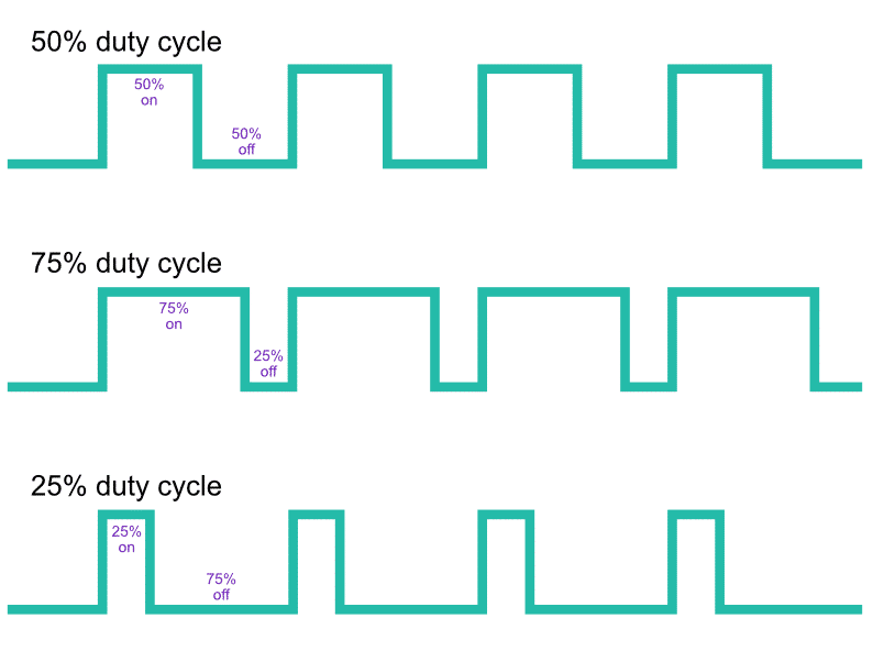
PWM & Fancy LED
PWM stands for Pulse Width Modulation, it’s a type of signal that isn’t just “on” or “off”. It’s oscillating between the 2 with a certain frequency, and a duty cycle.
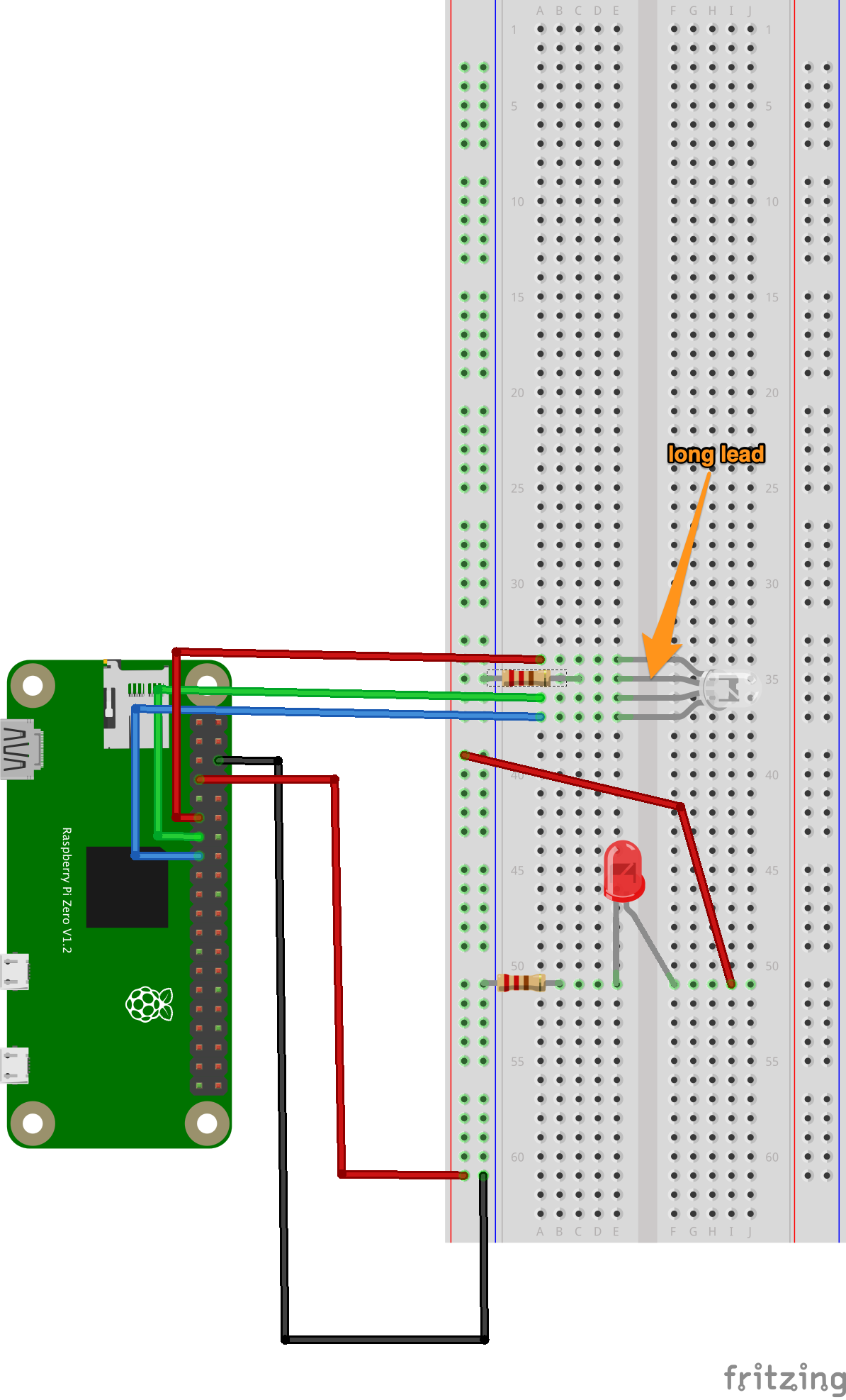
RGB LED Circuit
Please grab:
- 1 RGB LED
- 1 more 220 Ohm resistor
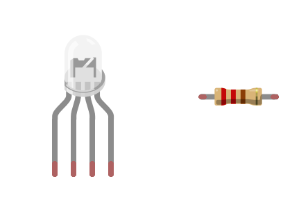
and build the following circuit:
This is the kind of code that we’re used to:
# import needed modules
import time
import RPi.GPIO as GPIO

GPIO.setmode( GPIO.BCM )

r = 17
g = 27
b = 22

GPIO.setup( r, GPIO.OUT )
GPIO.setup( g, GPIO.OUT )
GPIO.setup( b, GPIO.OUT )
GPIO.output( r, 0 )
GPIO.output( g, 0 )
GPIO.output( b, 0 )

print( "red" )
GPIO.output( r, 1 )
time.sleep( 2 )
GPIO.output( r, 0 )

print( "green" )
GPIO.output( g, 1 )
time.sleep( 2 )
GPIO.output( g, 0 )

print( "blue" )
GPIO.output( b, 1 )
time.sleep( 2 )
GPIO.output( b, 0 )

# the program is finished, we put things back in their original state
GPIO.cleanup()
Why RGB?
Now with PWM
# import needed modules
import time
import RPi.GPIO as GPIO

GPIO.setmode( GPIO.BCM )

r = 17
g = 27
b = 22

GPIO.setup( r, GPIO.OUT )
GPIO.setup( g, GPIO.OUT )
GPIO.setup( b, GPIO.OUT )

r_pwm = GPIO.PWM( r, 50 )
g_pwm = GPIO.PWM( g, 50 )
b_pwm = GPIO.PWM( b, 50 )

r_pwm.start( 0 )
g_pwm.start( 0 )
b_pwm.start( 0 )

print( "red" )
print( "  25" )
r_pwm.ChangeDutyCycle( 25 )
time.sleep( 0.5 )
print( "  50" )
r_pwm.ChangeDutyCycle( 50 )
time.sleep( 0.5 )
print( "  75" )
r_pwm.ChangeDutyCycle( 75 )
time.sleep( 0.5 )
print( "  100" )
r_pwm.ChangeDutyCycle( 100 )
time.sleep( 0.5 )
r_pwm.ChangeDutyCycle( 0 )

print( "green" )
print( "  25" )
g_pwm.ChangeDutyCycle( 25 )
time.sleep( 0.5 )
print( "  50" )
g_pwm.ChangeDutyCycle( 50 )
time.sleep( 0.5 )
print( "  75" )
g_pwm.ChangeDutyCycle( 75 )
time.sleep( 0.5 )
print( "  100" )
g_pwm.ChangeDutyCycle( 100 )
time.sleep( 0.5 )
g_pwm.ChangeDutyCycle( 0 )

print( "blue" )
print( "  25" )
b_pwm.ChangeDutyCycle( 25 )
time.sleep( 0.5 )
print( "  50" )
b_pwm.ChangeDutyCycle( 50 )
time.sleep( 0.5 )
print( "  75" )
b_pwm.ChangeDutyCycle( 75 )
time.sleep( 0.5 )
print( "  100" )
b_pwm.ChangeDutyCycle( 100 )
time.sleep( 0.5 )
b_pwm.ChangeDutyCycle( 0 )

# the program is finished, we put things back in their original state
GPIO.cleanup()
That’s how TVs work, zoom in on LED? zoom in on screen?
Try to get a pink.
Buttons
# import needed modules
import time
import RPi.GPIO as GPIO
import functionwebexpose

GPIO.setmode( GPIO.BCM )

r = 17
g = 27
b = 22

GPIO.setup( r, GPIO.OUT )
GPIO.setup( g, GPIO.OUT )
GPIO.setup( b, GPIO.OUT )

r_pwm = GPIO.PWM( r, 50 )
g_pwm = GPIO.PWM( g, 50 )
b_pwm = GPIO.PWM( b, 50 )

r_pwm.start( 0 )
g_pwm.start( 0 )
b_pwm.start( 0 )

functionwebexpose.server_start()


def led_color( r, g, b ):
    print( "> LED color( " + r + ", " + g + ", " + b + ")" )
    r = int( r )
    g = int( g )
    b = int( b )
    if r<0 or r>100:
        print( "> ERROR: r value needs to be between 0 and 100" )
        return False
    if g<0 or g>100:
        print( "> ERROR: g value needs to be between 0 and 100" )
        return False
    if b<0 or b>100:
        print( "> ERROR: b value needs to be between 0 and 100" )
        return False

    r_pwm.ChangeDutyCycle( r )
    g_pwm.ChangeDutyCycle( g )
    b_pwm.ChangeDutyCycle( b )

functionwebexpose.register( '<button>LED color</button><input type="number" placeholder="r" min="0" max="100"/><input type="number" placeholder="g" min="0" max="100"/><input type="number" placeholder="b" min="0" max="100"/>', led_color )


# this does nothing except prevent the program from stopping immediately
while True:
    time.sleep( 1 )

# the program is finished, we put things back in their original state
GPIO.cleanup()
Progressive PWM
You don’t have the whole working code here, only the interesting parts, try to integrate them within your code.
import threadingr_value = 0
r_increase_ongoing = False
def r_increase_start():
global r_increase_ongoing
print( "> r_increase_start" )
r_increase_ongoing = True
r_increase_ongoing_thread = threading.Thread( target=r_increase_operation )
r_increase_ongoing_thread.start()
def r_increase_operation():
global r_increase_ongoing, r_value
while r_increase_ongoing:
r_value = r_value + 1
if r_value>100:
r_value = 100
print( "> r_value: " + str(r_value) )
r_pwm.ChangeDutyCycle( r_value )
time.sleep( 0.1 )
def r_increase_stop():
global r_increase_ongoing
print( "> r_increase_stop" )
r_increase_ongoing = Falsefunctionwebexpose.register( "<button>R+</button>", r_increase_start, r_increase_stop )Work your copy paste magic to add “decrease”. Other colors if time allows.
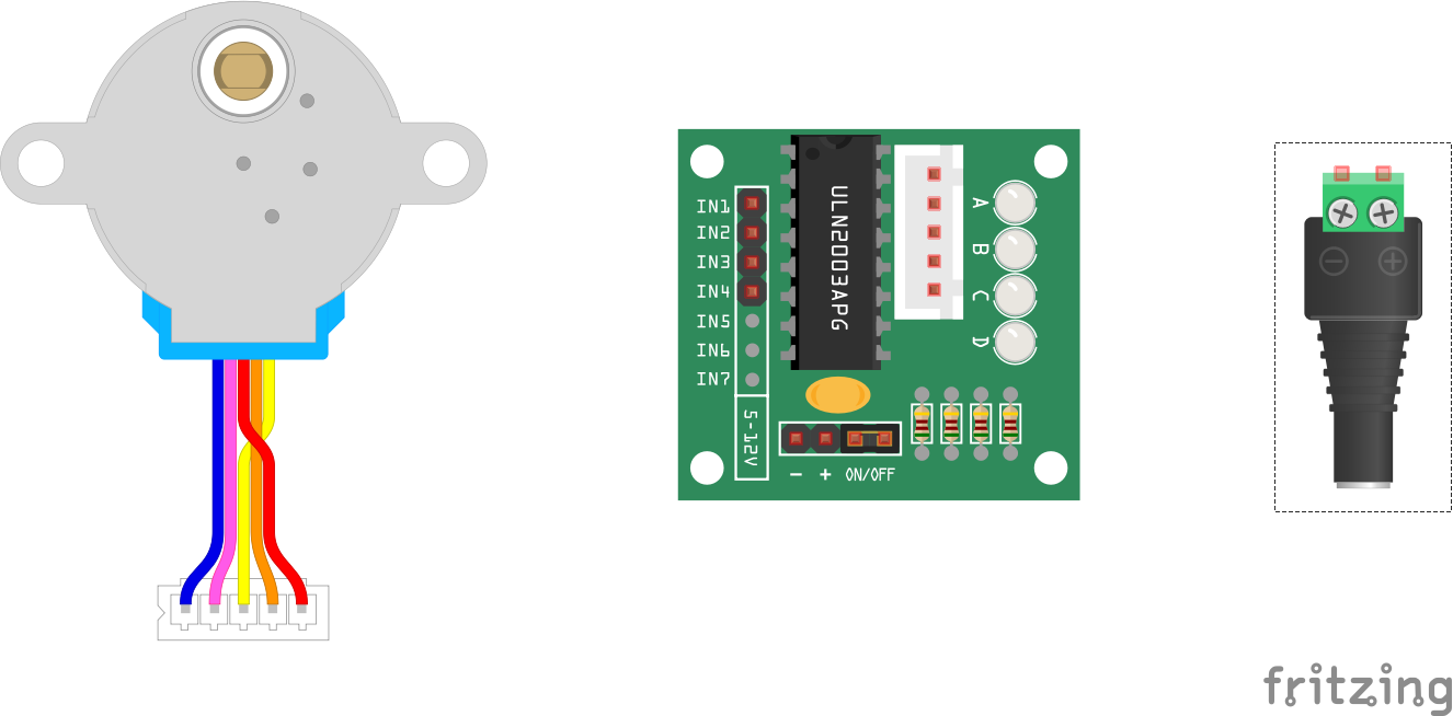
Motors
Please grab a 28BYJ-48 stepper motor and, driver board, and 12v plug.
DC motors Vs Stepper motors
Why do you think a drawing machine needs a stepper motor and not a DC motor?
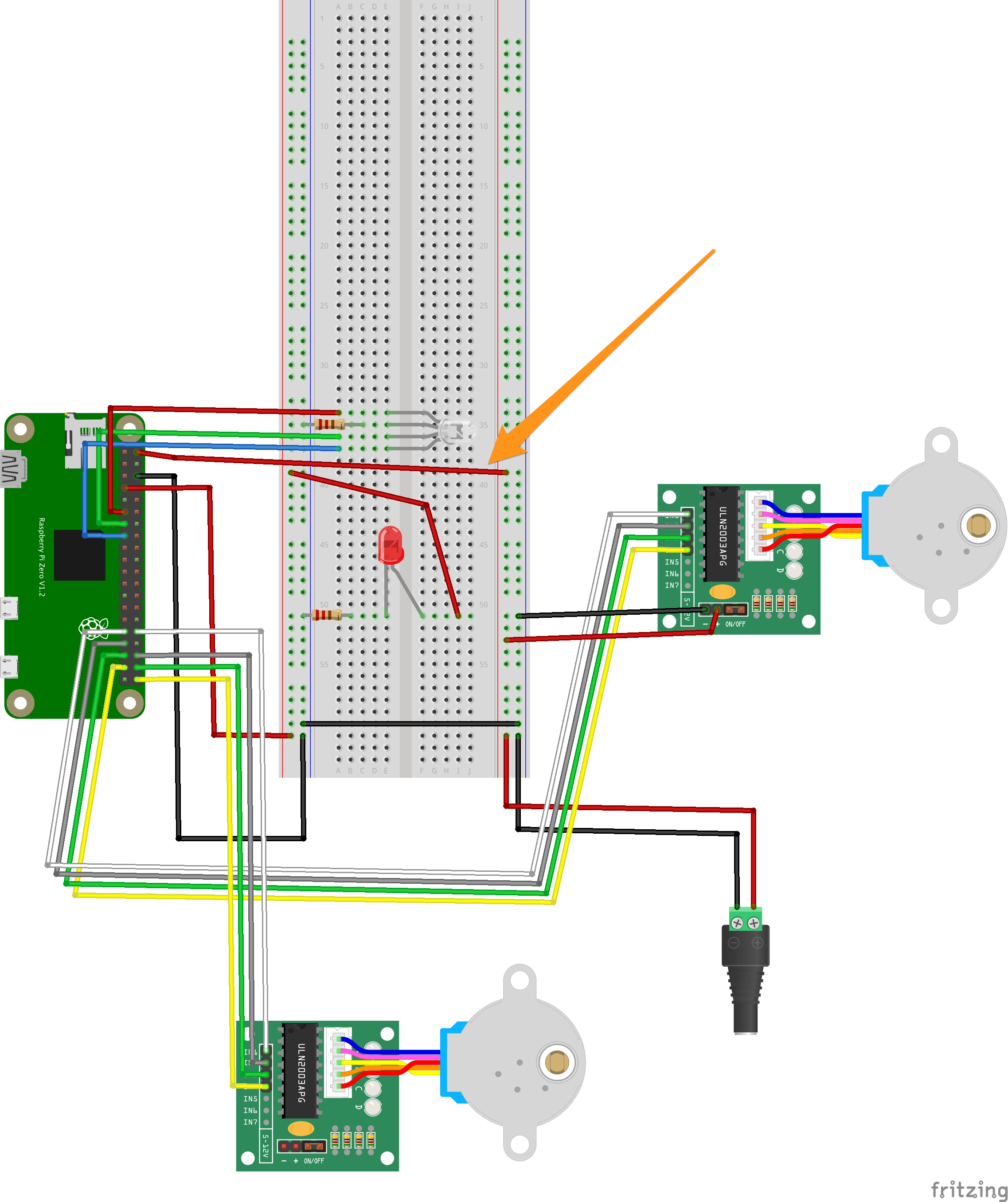
12v & Stepper Wiring
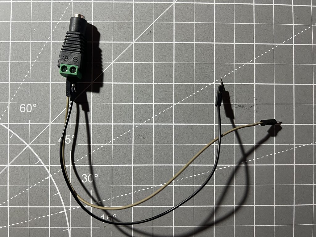
Plug in 12v on the other side of the breadboard !make sure it’s not getting power yet!
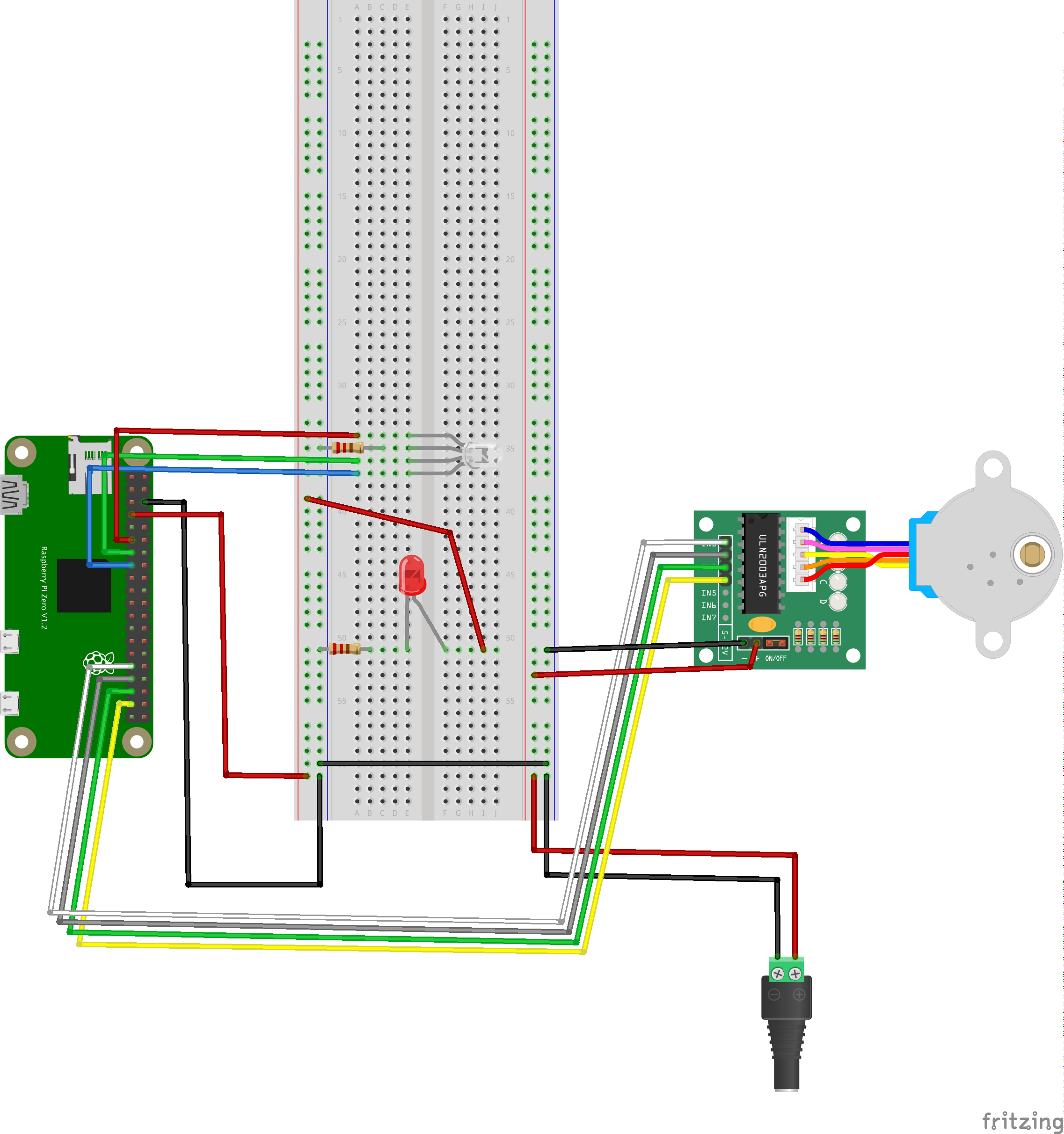
Note the linked grounds.
Main Code
Chasing the magnet. Again this code is not complete, your job is to integrate it within your existing code.
horizontal_in1 = 6
horizontal_in2 = 13
horizontal_in3 = 19
horizontal_in4 = 26

GPIO.setup( horizontal_in1, GPIO.OUT )
GPIO.output( horizontal_in1, 0 )
GPIO.setup( horizontal_in2, GPIO.OUT )
GPIO.output( horizontal_in2, 0 )
GPIO.setup( horizontal_in3, GPIO.OUT )
GPIO.output( horizontal_in3, 0 )
GPIO.setup( horizontal_in4, GPIO.OUT )
GPIO.output( horizontal_in4, 0 )
horizontal_index = 0
def horizontal_take_step( direction ):
global horizontal_index
if horizontal_index==0:
GPIO.output( horizontal_in1, 1 )
GPIO.output( horizontal_in2, 0 )
GPIO.output( horizontal_in3, 0 )
GPIO.output( horizontal_in4, 0 )
elif horizontal_index==1:
GPIO.output( horizontal_in1, 1 )
GPIO.output( horizontal_in2, 1 )
GPIO.output( horizontal_in3, 0 )
GPIO.output( horizontal_in4, 0 )
elif horizontal_index==2:
GPIO.output( horizontal_in1, 0 )
GPIO.output( horizontal_in2, 1 )
GPIO.output( horizontal_in3, 0 )
GPIO.output( horizontal_in4, 0 )
elif horizontal_index==3:
GPIO.output( horizontal_in1, 0 )
GPIO.output( horizontal_in2, 1 )
GPIO.output( horizontal_in3, 1 )
GPIO.output( horizontal_in4, 0 )
elif horizontal_index==4:
GPIO.output( horizontal_in1, 0 )
GPIO.output( horizontal_in2, 0 )
GPIO.output( horizontal_in3, 1 )
GPIO.output( horizontal_in4, 0 )
elif horizontal_index==5:
GPIO.output( horizontal_in1, 0 )
GPIO.output( horizontal_in2, 0 )
GPIO.output( horizontal_in3, 1 )
GPIO.output( horizontal_in4, 1 )
elif horizontal_index==6:
GPIO.output( horizontal_in1, 0 )
GPIO.output( horizontal_in2, 0 )
GPIO.output( horizontal_in3, 0 )
GPIO.output( horizontal_in4, 1 )
elif horizontal_index==7:
GPIO.output( horizontal_in1, 1 )
GPIO.output( horizontal_in2, 0 )
GPIO.output( horizontal_in3, 0 )
GPIO.output( horizontal_in4, 1 )
if direction=="clockwise":
horizontal_index = horizontal_index + 1
if horizontal_index>7:
horizontal_index = 0
elif direction=="counterclockwise":
horizontal_index = horizontal_index - 1
if horizontal_index<0:
horizontal_index = 7
else:
print( "error: unknown direction - " + direction )
time.sleep( 0.05 )functionwebexpose.register( "<button>Horizontal Take a Step</button><input type=\"text\" placeholder=\"direction\"/>", horizontal_take_step )Note how the LEDs are following the code.
Tiny steps! Very accurate.
Giving Ourselves more Buttons
How would you write this one?
functionwebexpose.register( "<button>Horizontal Take X Steps</button><input type=\"text\" placeholder=\"direction\"/><input type=\"number\" placeholder=\"X\" min=\"0\"/>", horizontal_take_x_steps )Active Braking & Heat
def horizontal_deenergize():
    GPIO.output( horizontal_in1, 0 )
    GPIO.output( horizontal_in2, 0 )
    GPIO.output( horizontal_in3, 0 )
    GPIO.output( horizontal_in4, 0 )
functionwebexpose.register( "<button>Horizontal Denergize</button>", horizontal_deenergize )These ones are Free 🙂
horizontal_take_steps_ongoing = False
def horizontal_take_steps_start( direction ):
    global horizontal_take_steps_ongoing

    print( "> horizontal_take_steps_start" )
    horizontal_take_steps_ongoing = True
    horizontal_take_steps_ongoing_thread = threading.Thread( target=horizontal_take_steps_start_operation, kwargs={"direction":direction} )
    horizontal_take_steps_ongoing_thread.start()


def horizontal_take_steps_start_operation( direction ):
    global horizontal_take_steps_ongoing

    while horizontal_take_steps_ongoing:
        horizontal_take_step( direction )
    horizontal_deenergize()


def horizontal_take_steps_stop():
    global horizontal_take_steps_ongoing

    print( "> horizontal_take_steps_stop" )
    horizontal_take_steps_ongoing = False


def horizontal_take_steps_start_clockwise():
    horizontal_take_steps_start( "clockwise" )


def horizontal_take_steps_start_counterclockwise():
    horizontal_take_steps_start( "counterclockwise" )
functionwebexpose.register( "<button>></button>", horizontal_take_steps_start_clockwise, horizontal_take_steps_stop )
functionwebexpose.register( "<button><</button>", horizontal_take_steps_start_counterclockwise, horizontal_take_steps_stop )How would you make it go faster? As with the LED blinking, if we take small distinct actions very fast, they become smooth.
Attaching the Motor
While we’re here, might as well attach the other one.
Organizing Code
we’re starting to have a lot of function, let’s tidy things up a bit
functionwebexpose.arbitrary_html( "<strong>RGB LED</strong>" )
functionwebexpose.arbitrary_html( "<br/>" )
Make sure the code works every time you make a change.
All You for #2
(but please pick pins 12, 16, 20 & 21) pinout.xyz
Bring functions in from the horizontal motor 1 by 1, make sure to test each one before moving on to the next.
Organizing Cables
velcro
take picture of pins
make sure you leave slack to shake the etch a sketch
Calibration
Use the “Take X Steps” functions to count how many steps it takes to travel horizontally and vertically. Leave some padding on the edges, and add up small (~1000 steps) increments.
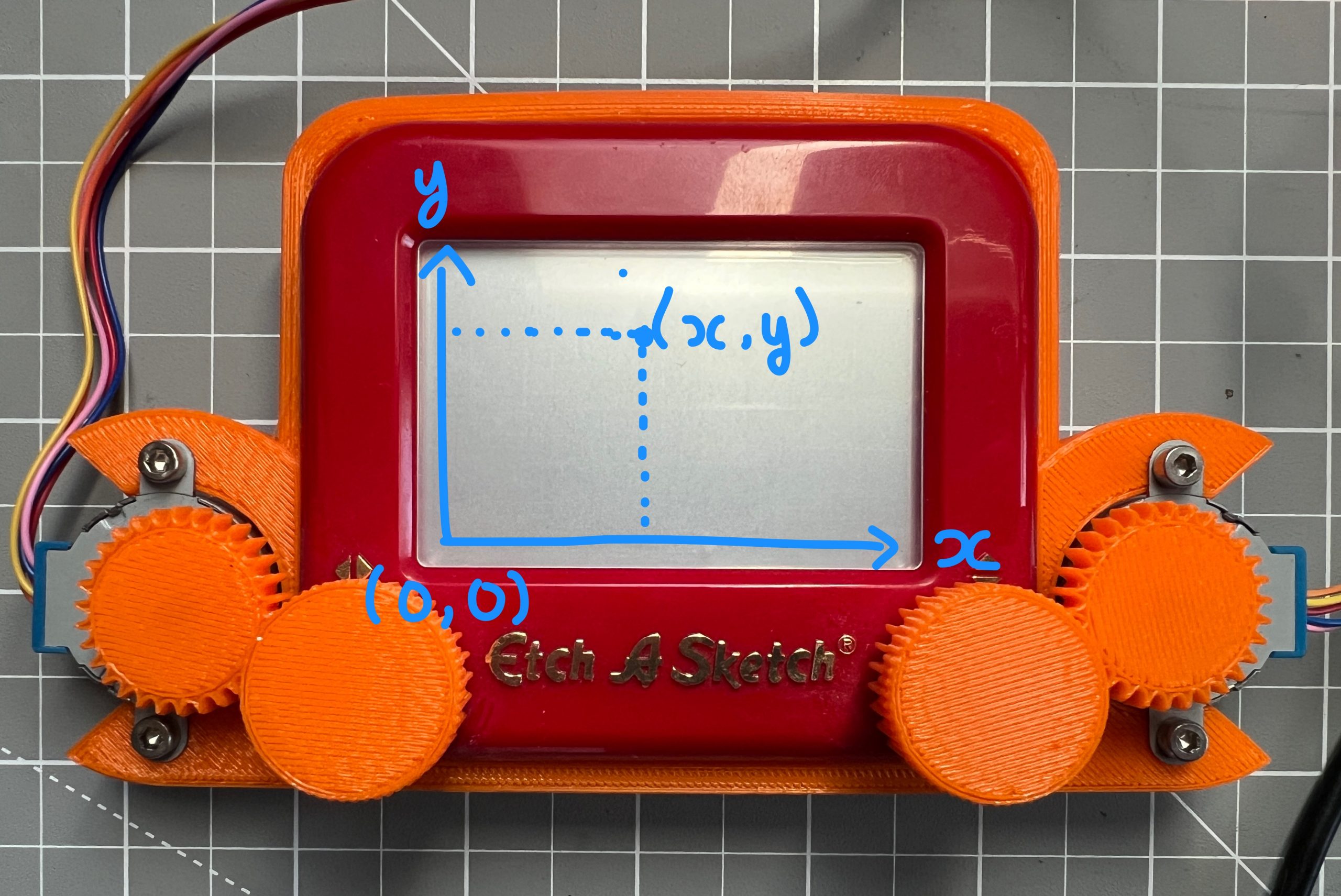
When you start at (0,0), how many steps in either direction do you need to take to get to (100, 100)?
And when you are at (100,100), how many steps in either direction do you need to take to get to (1000, 1000)?
Drawing
current_x = 0
current_y = 0
def go_to( new_x, new_y ):
    global current_x, current_y
    new_x = int( new_x )
    new_y = int( new_y )

    print( "> go_to (" + str(current_x) + "," + str(current_y) + ") -> (" + str(new_x) + "," + str(new_y) + ")" )

    # we compute the number of steps we need to take and the spin direction
    horizontal_steps_to_take = new_x - current_x
    horizontal_direction = "clockwise"
    if horizontal_steps_to_take < 0:
        horizontal_direction = "counterclockwise"
        horizontal_steps_to_take *= -1

    vertical_steps_to_take = new_y - current_y
    vertical_direction = "clockwise"
    if vertical_steps_to_take < 0:
        vertical_direction = "counterclockwise"
        vertical_steps_to_take *= -1

    print( ">   horizontal: " +  str(horizontal_steps_to_take) + " steps " + horizontal_direction )
    print( ">   vertical:" +  str(vertical_steps_to_take) + " steps " + vertical_direction )

    # actuation
    horizontal_take_x_steps( horizontal_direction, horizontal_steps_to_take )
    horizontal_deenergize()
    vertical_take_x_steps( vertical_direction, vertical_steps_to_take )
    vertical_deenergize()

    # keeping track of the new location
    current_x = new_x
    current_y = new_y
functionwebexpose.register( '<button>Go To</button><input type="number" placeholder="X" min="0"/><input type="number" placeholder="Y" min="0"/>', go_to )Let’s draw a simple square.
SVG

Removing USB Power
Untested 🙂 I didn’t have a 5V power supply at home.
More Drawing
Patterns & Algorithms
def draw_square_spiral():
    maximum = 6000
    offset = 300
    iteration = 0
    while (offset*iteration)<(maximum/2):
        go_to( iteration*offset, maximum-iteration*offset )
        go_to( maximum-iteration*offset, maximum-iteration*offset )
        go_to( maximum-iteration*offset, iteration*offset )
        go_to( iteration*offset, iteration*offset )
        iteration += 1
functionwebexpose.register( '<button>Draw Square Spiral</button>', draw_square_spiral )What Else can you Build?
rovers
stepper motors are everywhere, think about how a machine works next time you see one
That’s it!
did extremely well, very cool to see you handle code better every time. remember copy pasting and adjusting is what coders do a lot.
do try it by yourself
you didn’t break anything! no smoke, I’m leaving you an extra stepper just in case.
~$40 in parts: 14.72[etch-a-sketch]+(14.99/6*3)[steppers]+15[pi]+5[misc]
certificate
if you need help, ask your parents to text me.
Leave a Comment