Introduction
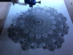
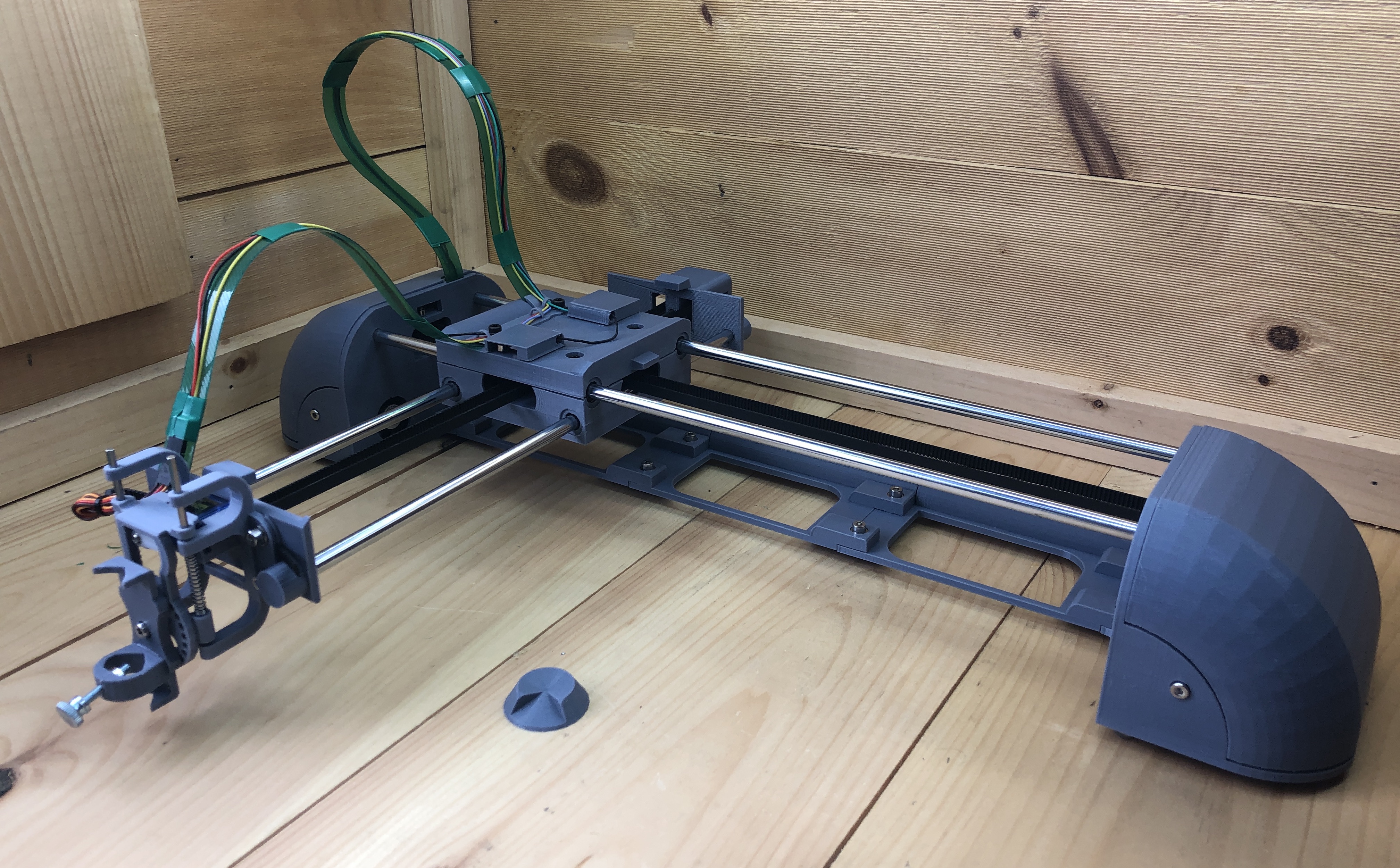
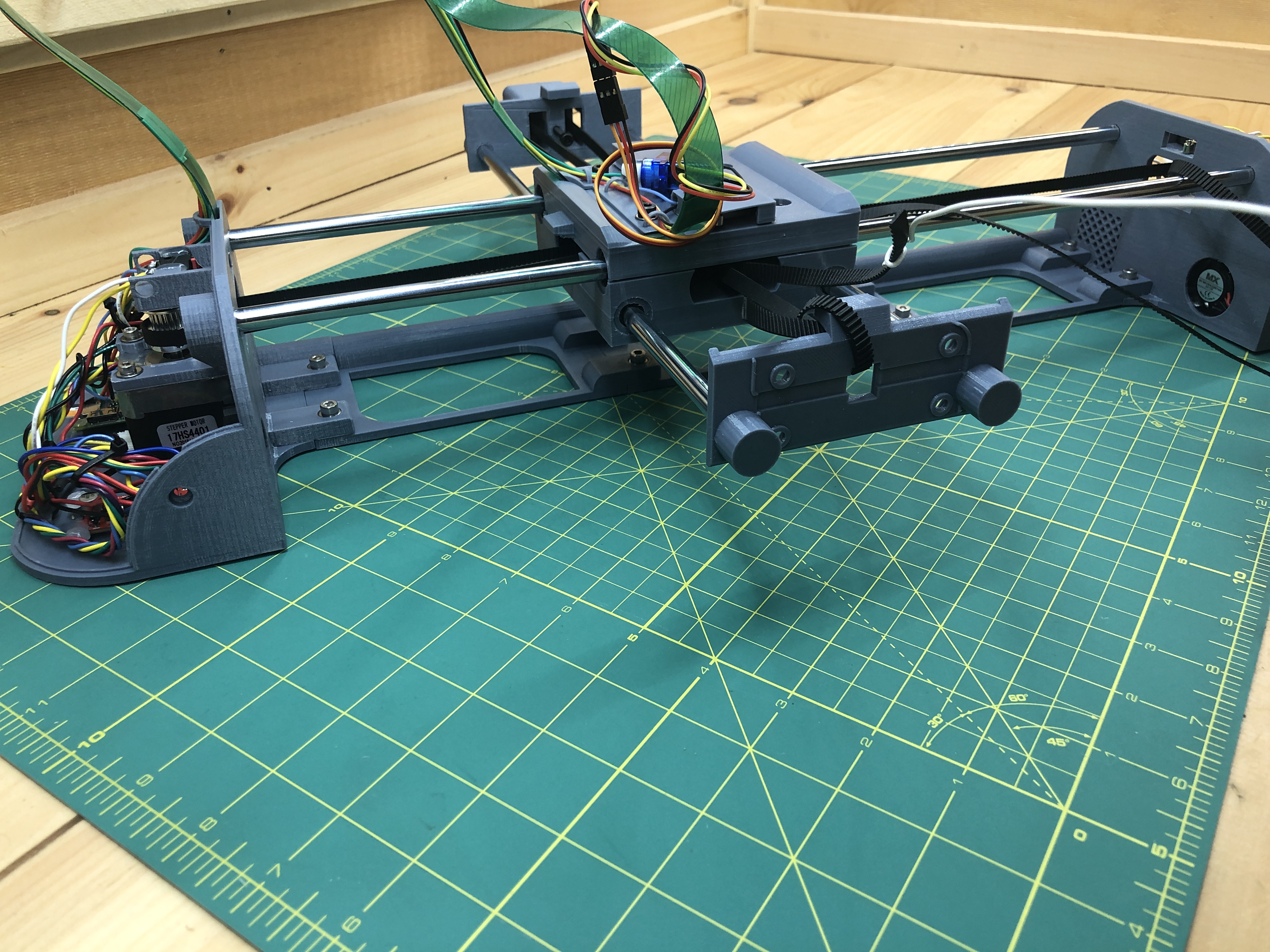
This is PlottyBot, a pen plotter you can build.
It’s based on a Raspberry Pi Zero W which means it’s loaded with software to make it easy to use. It also comes with novel features.
Features
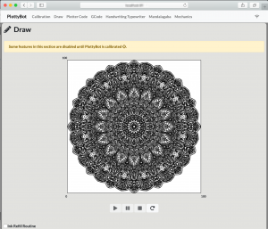
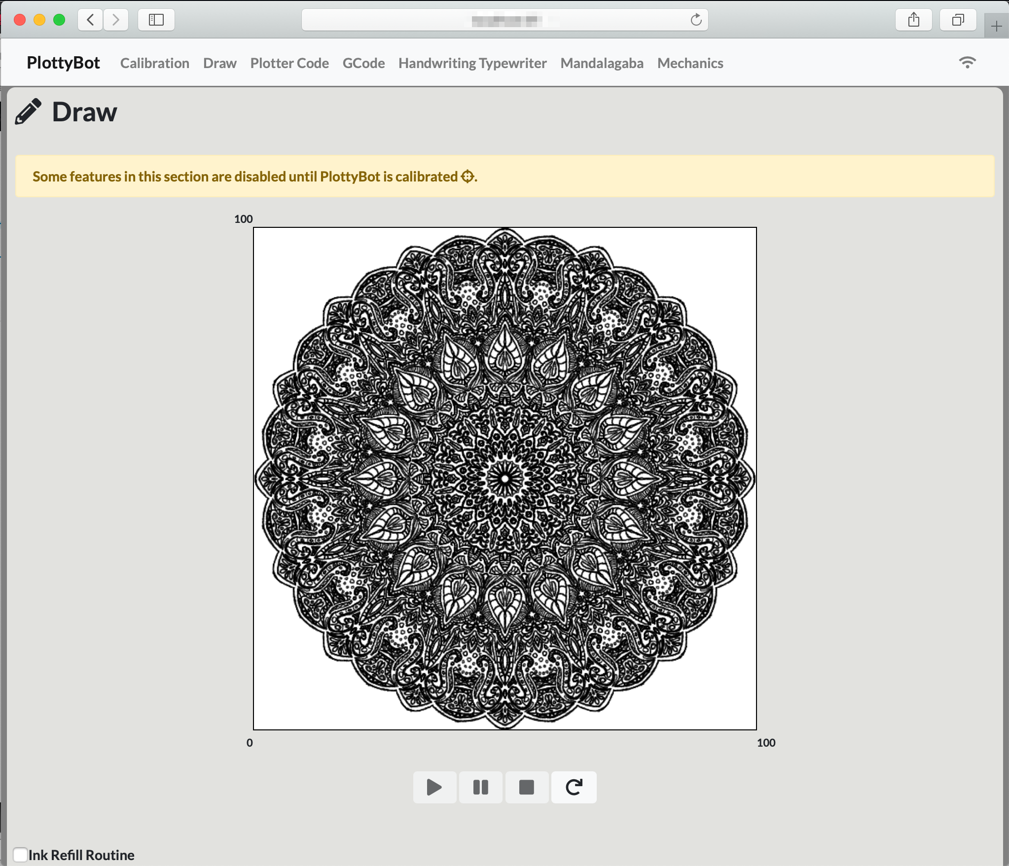
- Simple control from a web interface, with plot preview, play, pause & stop.
.
- Works on complex hours long plots without missing a step.
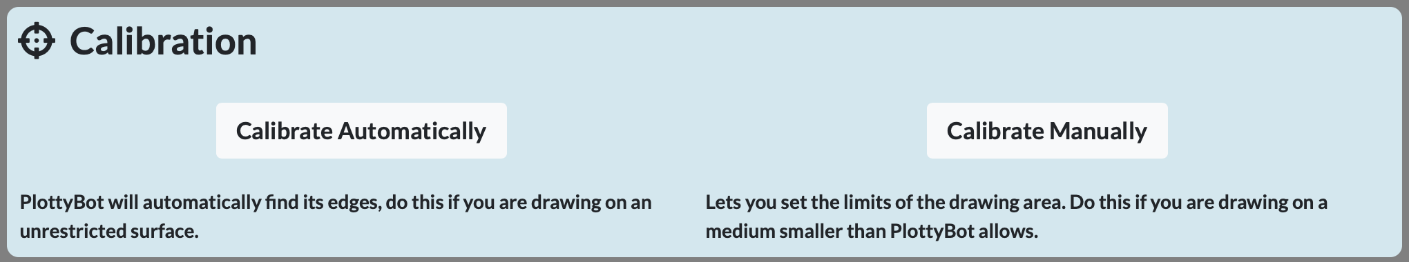
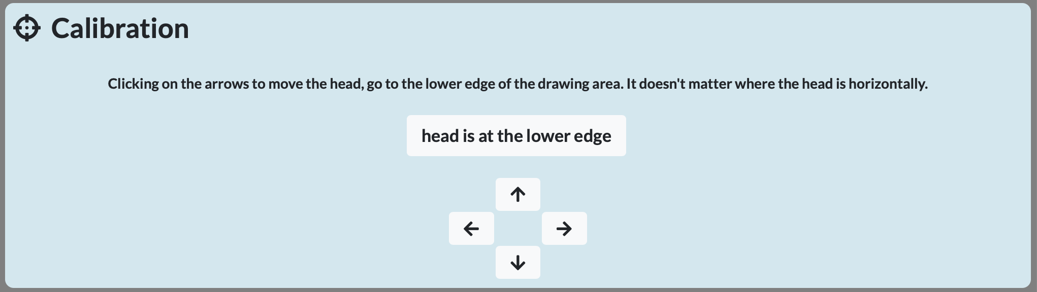
- Automatic calibration or manual calibration to work on smaller media.
.


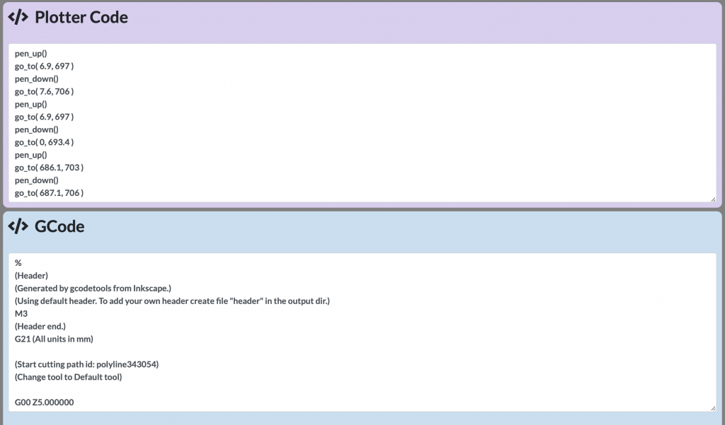
- GCode support, or simpler human readable (and kid friendly) Plotter code. Automatic conversion from GCode to Plotter code.
.
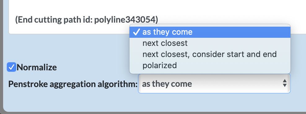
- Various pen stroke aggregation algorithms & normalization to drawing area.
.
- Internet enabled drawing
video soon to be released
- Handwriting Typewriter
- Local WiFi network where no Managed network is in range
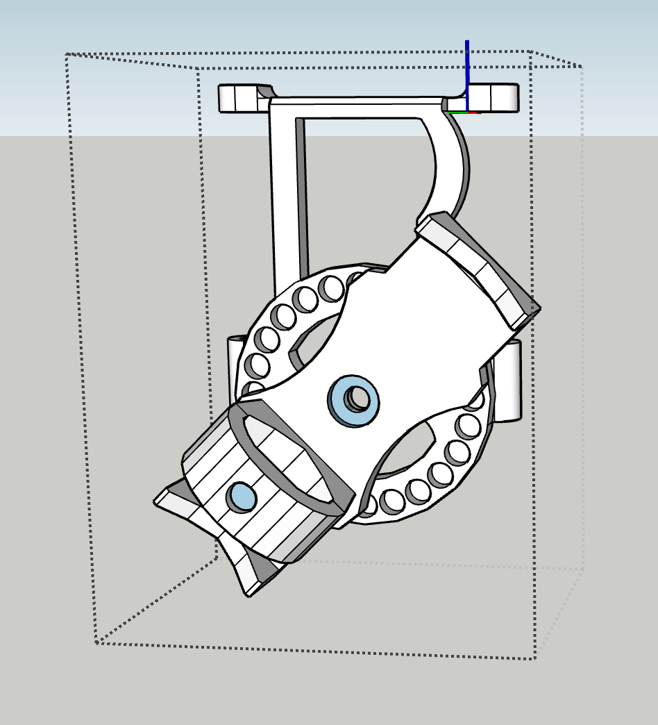
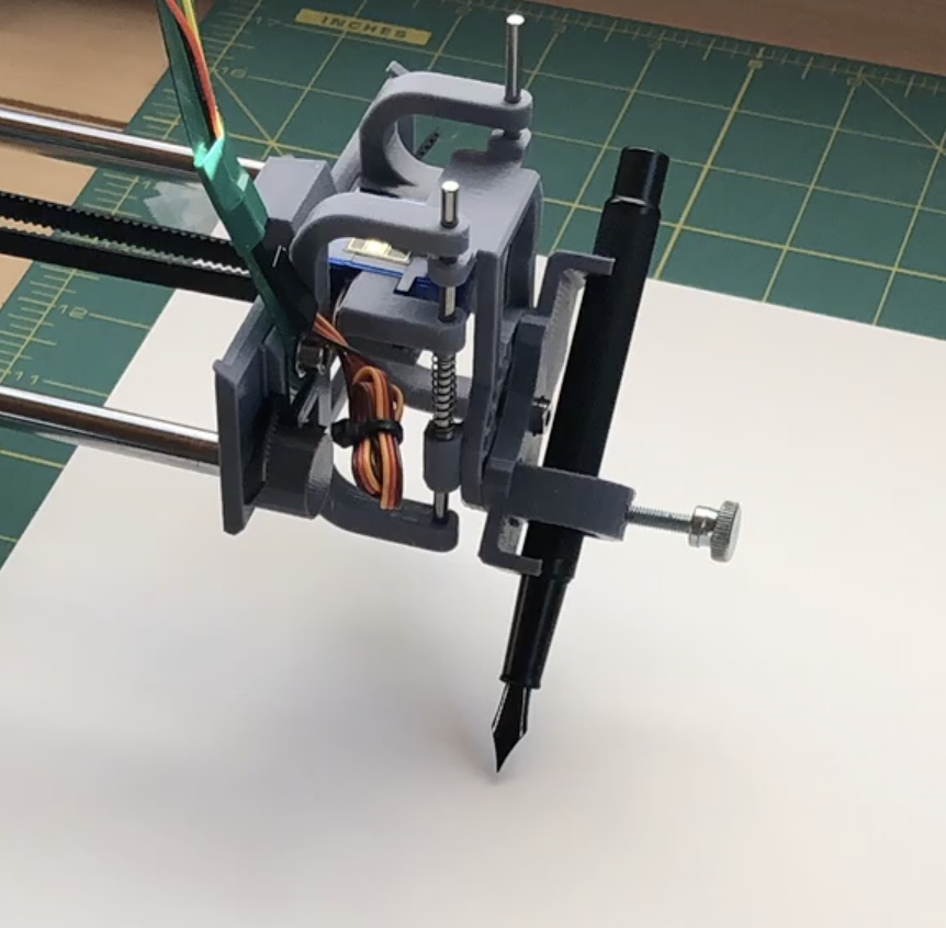
- Rotatable pen holder to accommodate various drawing instruments such as fountain pens.
.
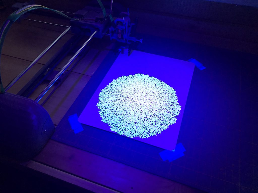
Using fountain pens gives you the ability to work with specialty inks such as UV ink.
- Ink Refill Routine for instruments which require it.
- Advanced tunables for every aspect of the machine’s operation.
.
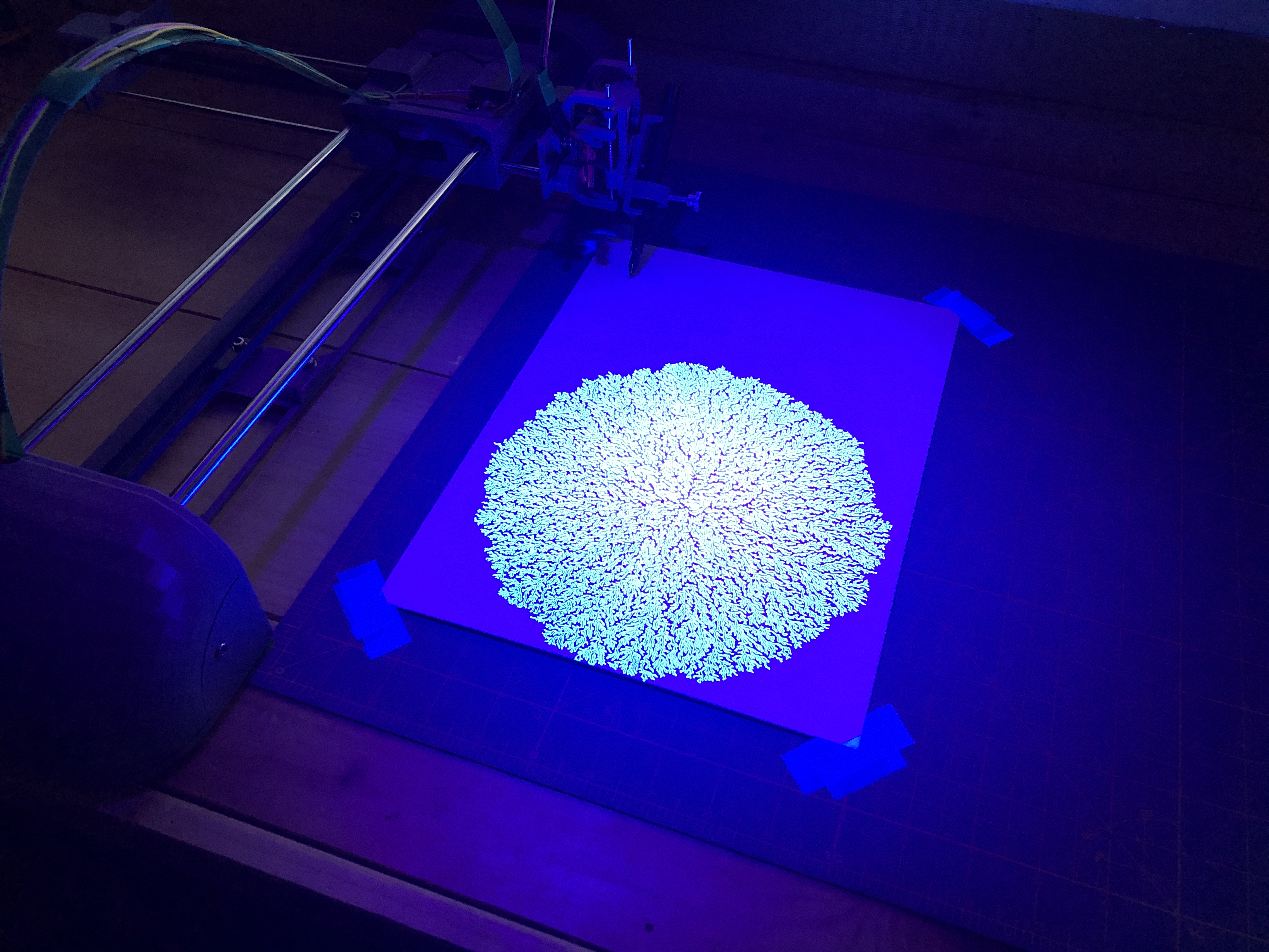

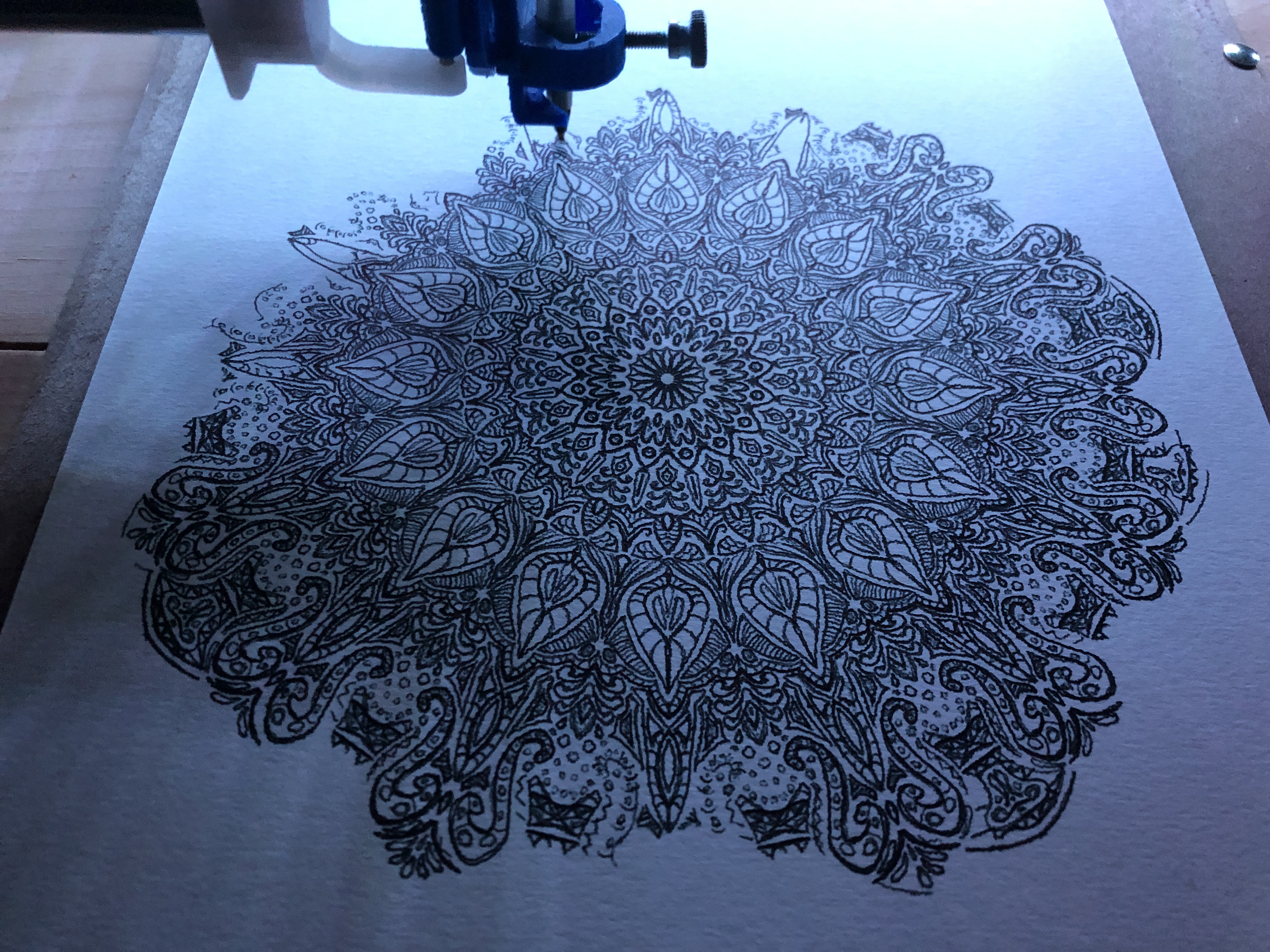
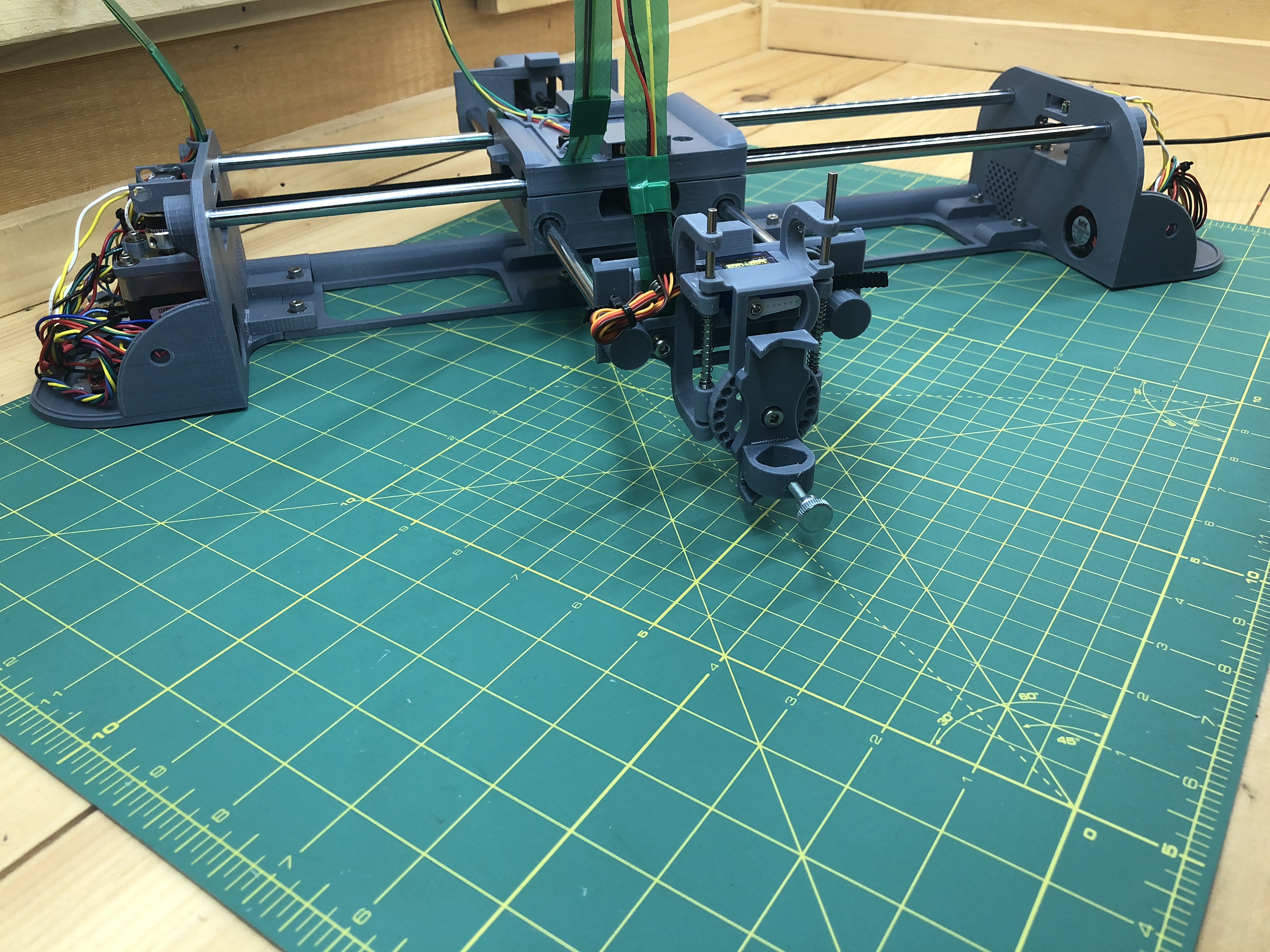
Finished Build
Downloads
Build Instructions
Parts to gather
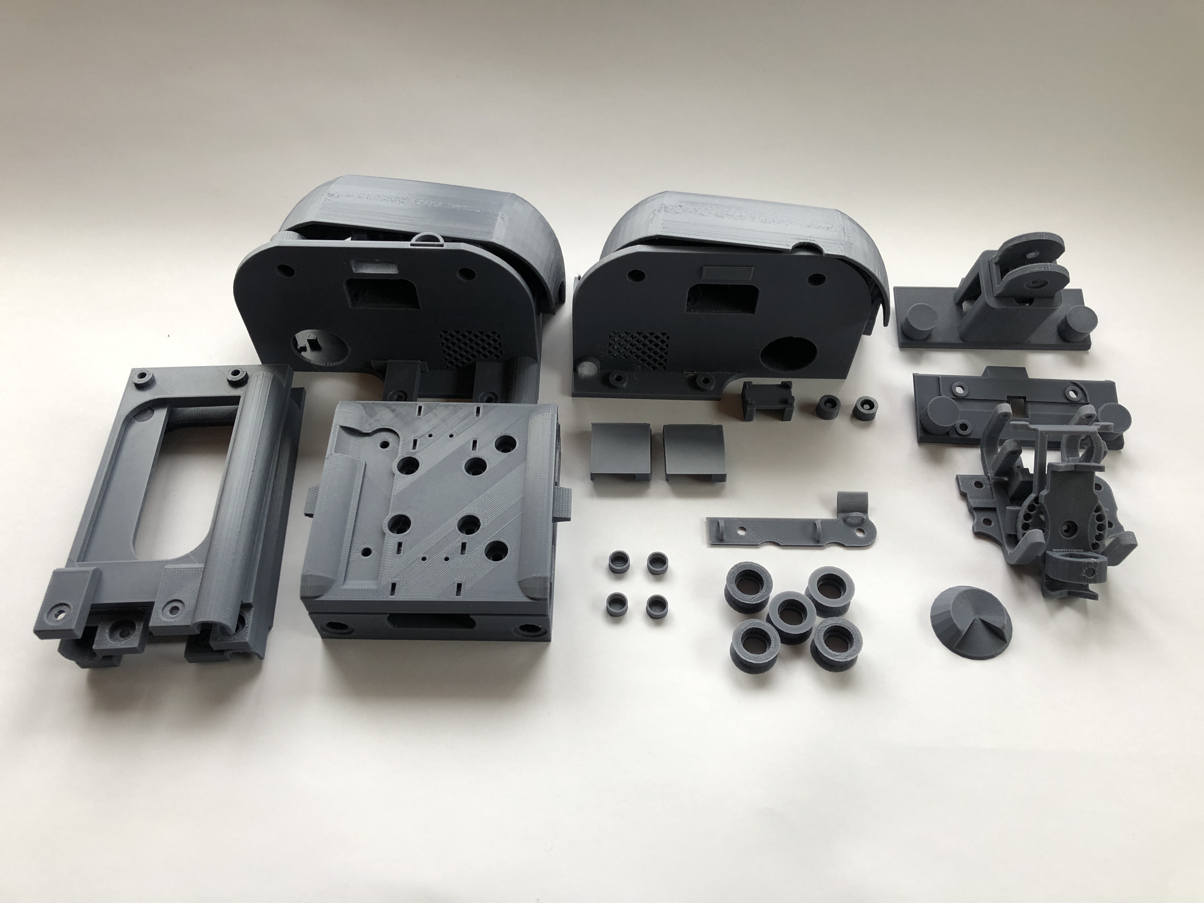
3D printed
Grab all the STL parts from here. Each part file has a name finishing with the quantity you need print of it.
When all are printed, you’ll have this:
Acquired
Tools to have
- soldering iron
- glue gun (or sugru mouldable glue)
- allen wrench set
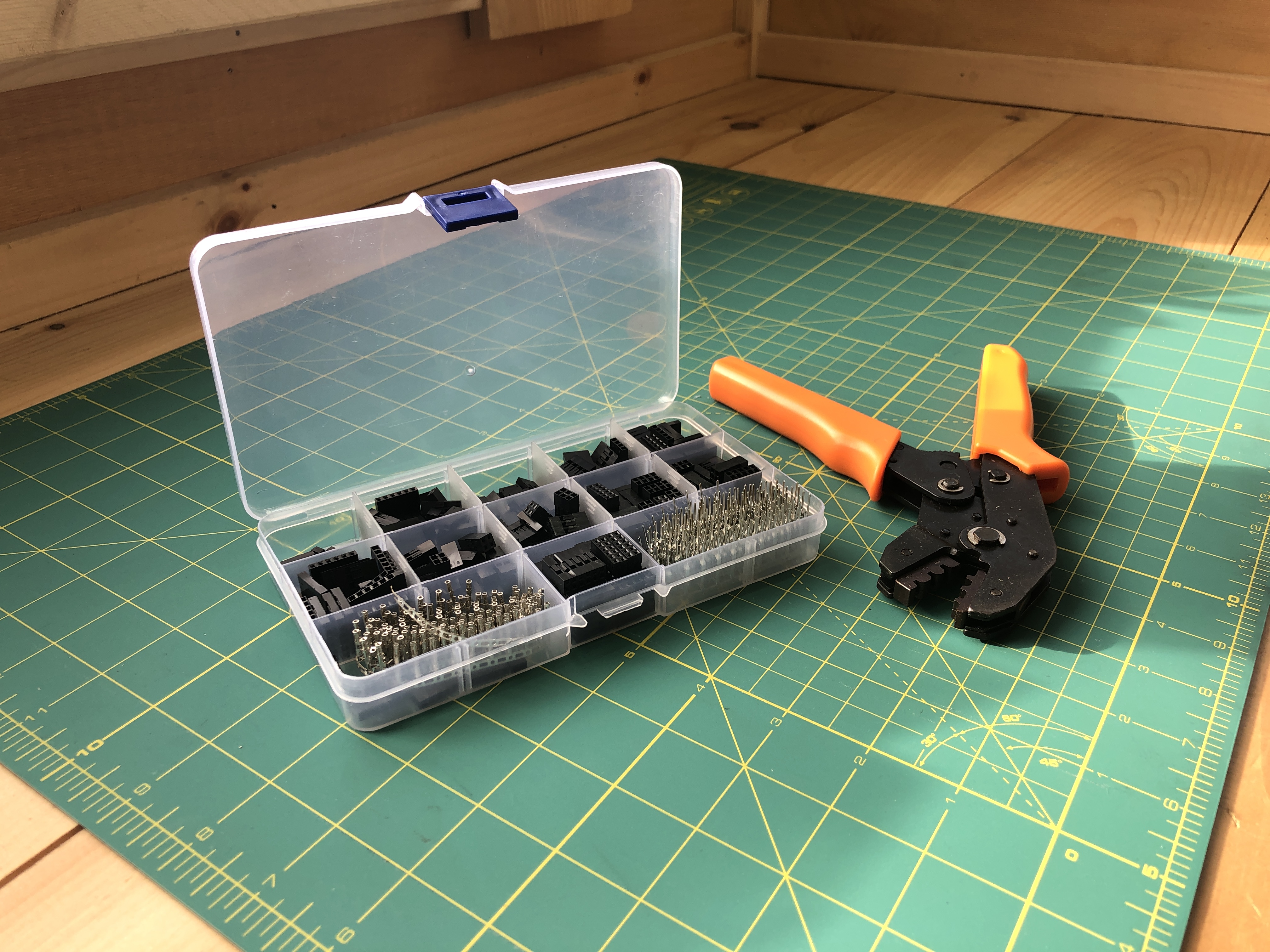
- dupont wire connection kit (possibly optional)
Consumables
wiring
Household items
bendable plastic you can cut
click pens to steal their perfectly sized springs
Circuit
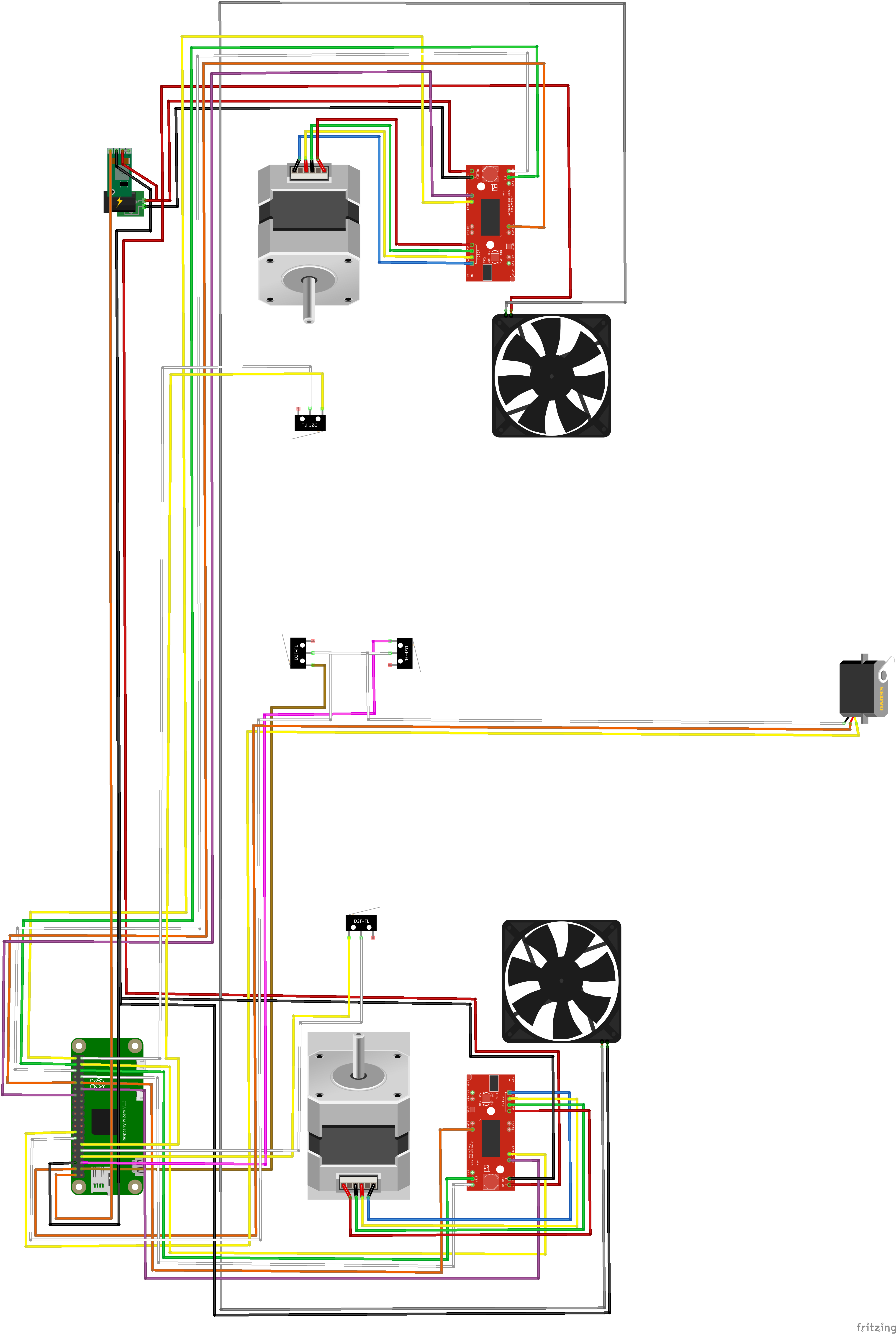
Here is a full representation of the final circuit where we’re going to build. We’ll take it step by step, this is only for reference.
Click image for full size
Step by Step
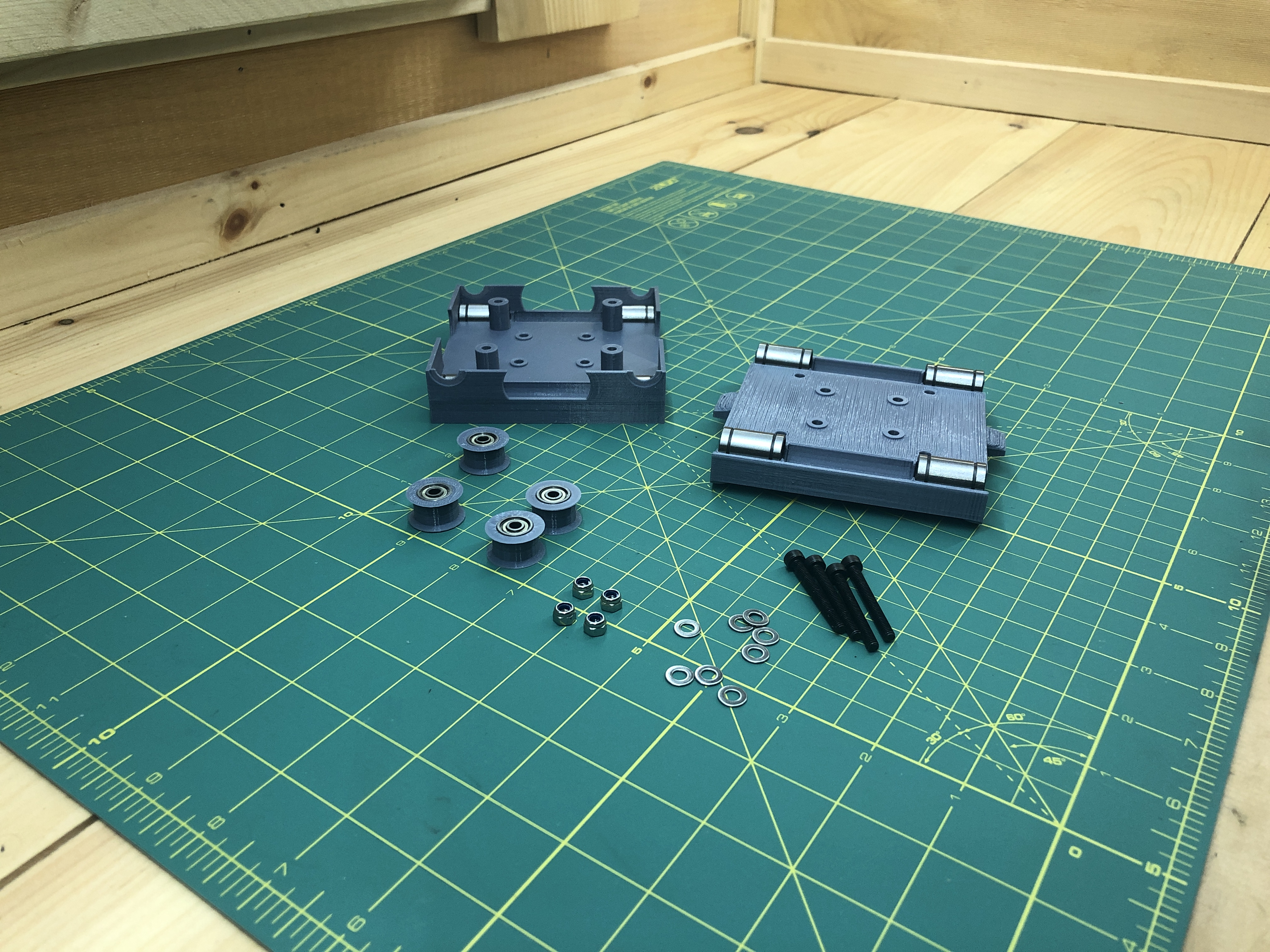
1. Gondola
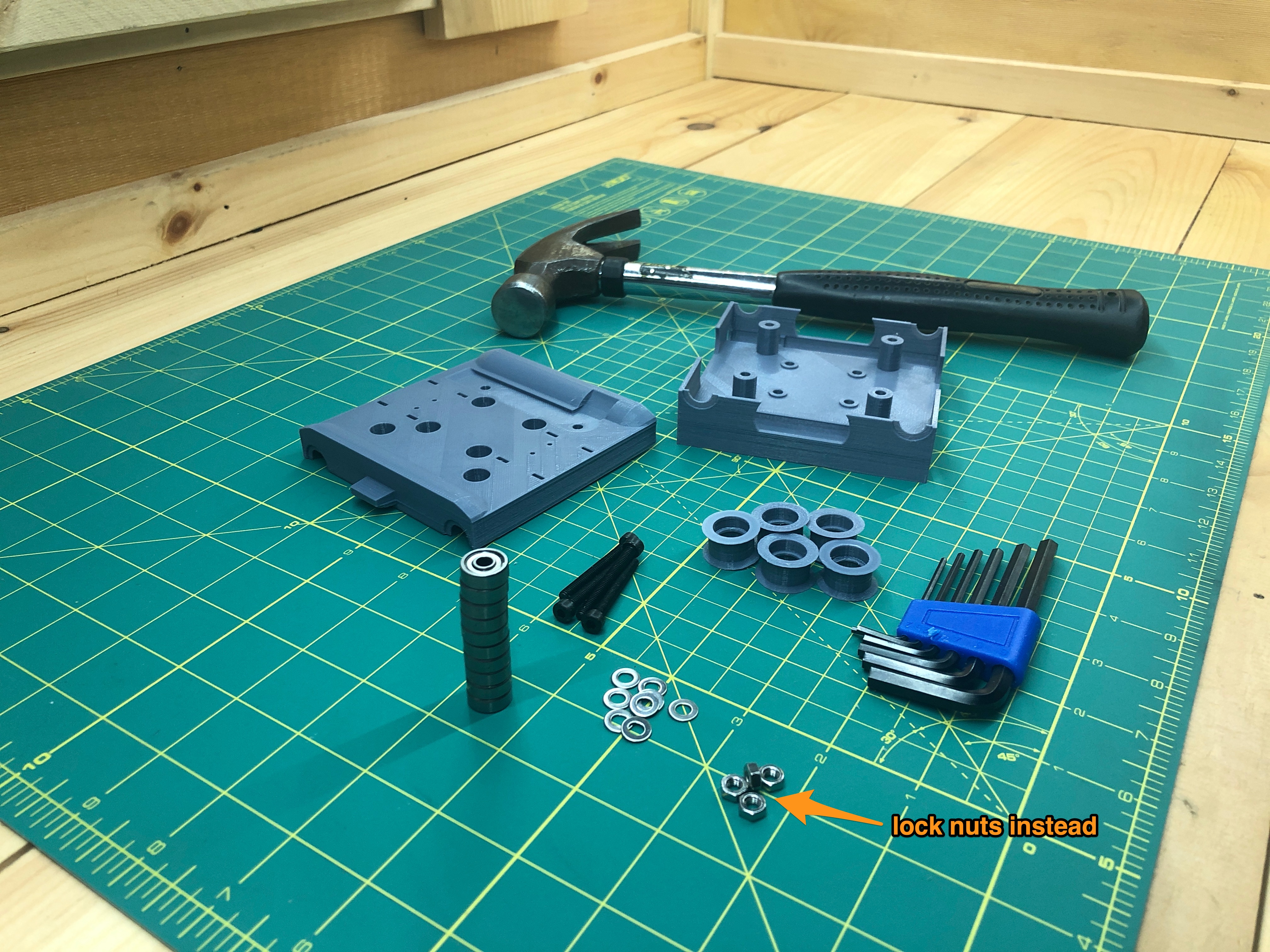
Hardware:
4 M4x35 hex screw
4 M4 lock nut
8 washers
10 bearings
8 LM8UU linear bearings
3D Parts:
gondola_bottom_x1
gondola_top_x1
belt_roller_x5
For each belt roller, gently hammer in 2 bearings, one on each side. Use a piece of wood or something to shield the bearings from the hammer.
Your belt rollers will look like this when you’re done:

Grab the LM8UU linear bearings, also grab one of the linear rods simply to test them before you commit them to your build.

You don’t want a bad linear bearing so it’s a good idea to run them along the rod and make sure they move smoothly. You’ll know immediately if one of them sticks, throw it away and get another one.
Now that you know all your linear bearings are up to par, insert them in each corner of gondola_bottom and gondola_top. You can pressure fit them.
And of course, gentle hammering can help, be really careful not to damage anything in the part.
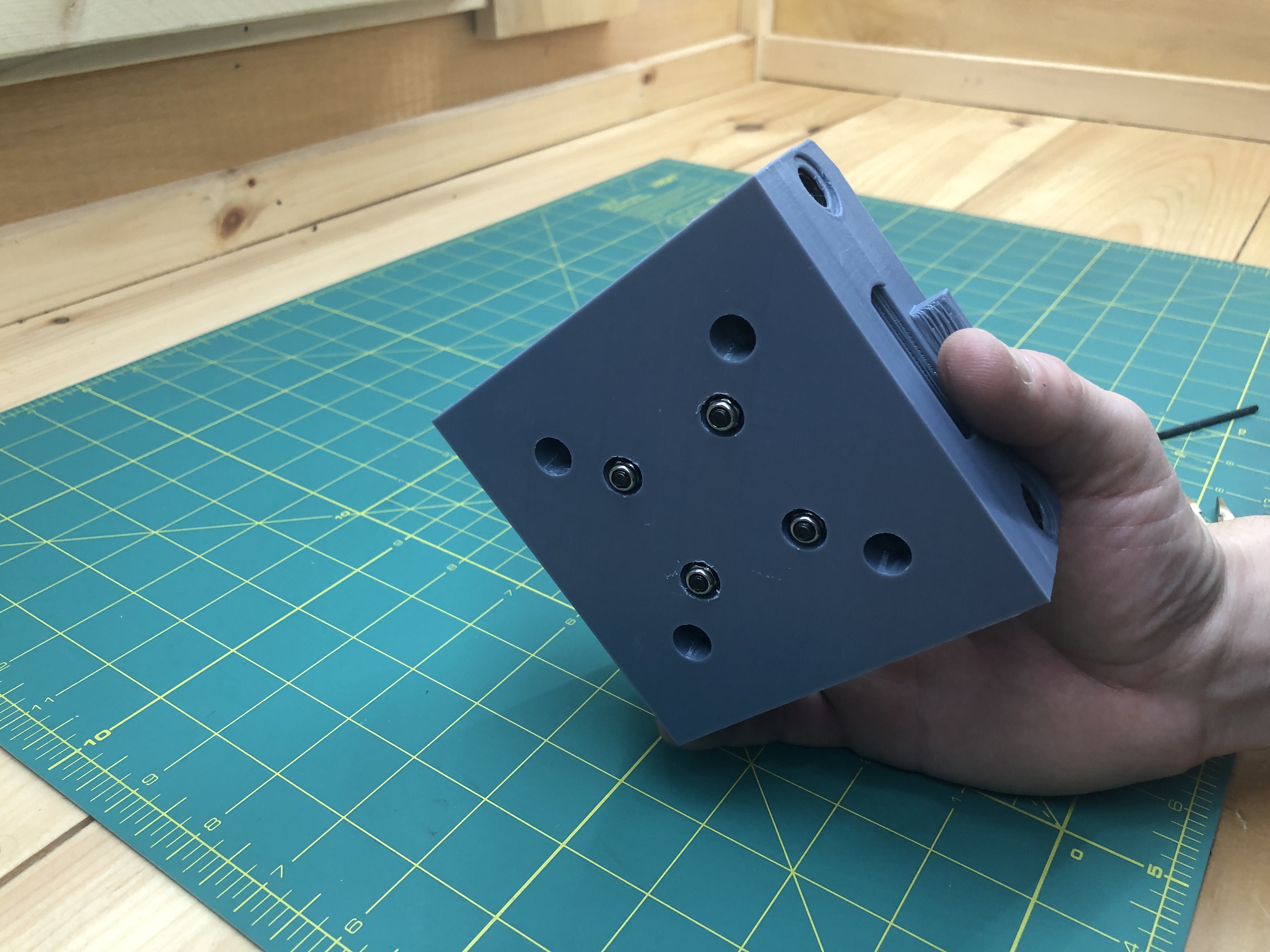
When you’re done, you’ll have a nice line of sight from one end to the other.
You can use the rod once more to make sure it runs smoothly through both bearings in a line.
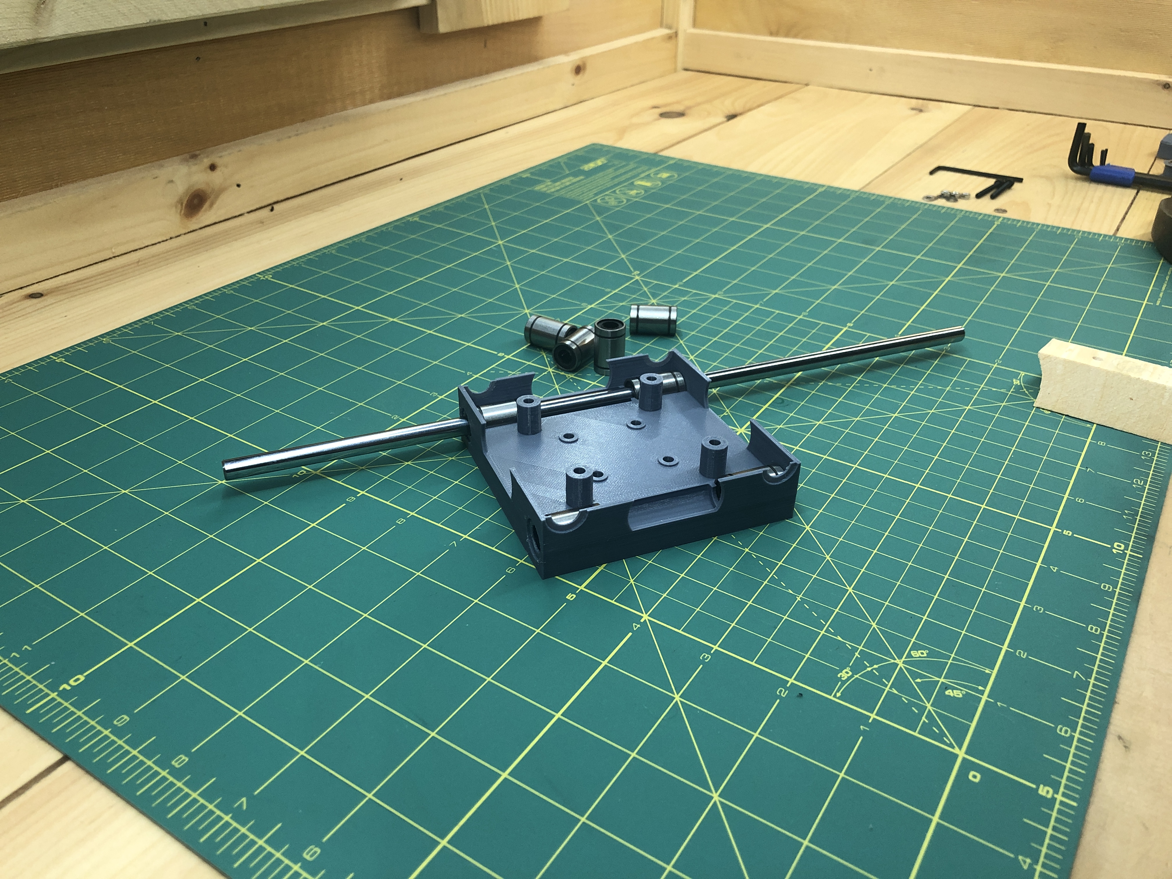
When you are done, both the top and bottom parts of your gondola will each have 4 linear bearings in their corners.

Get your belt rollers and the rest of the hardware.
Put the 4 M4x35 hex screws through the top part with washers.
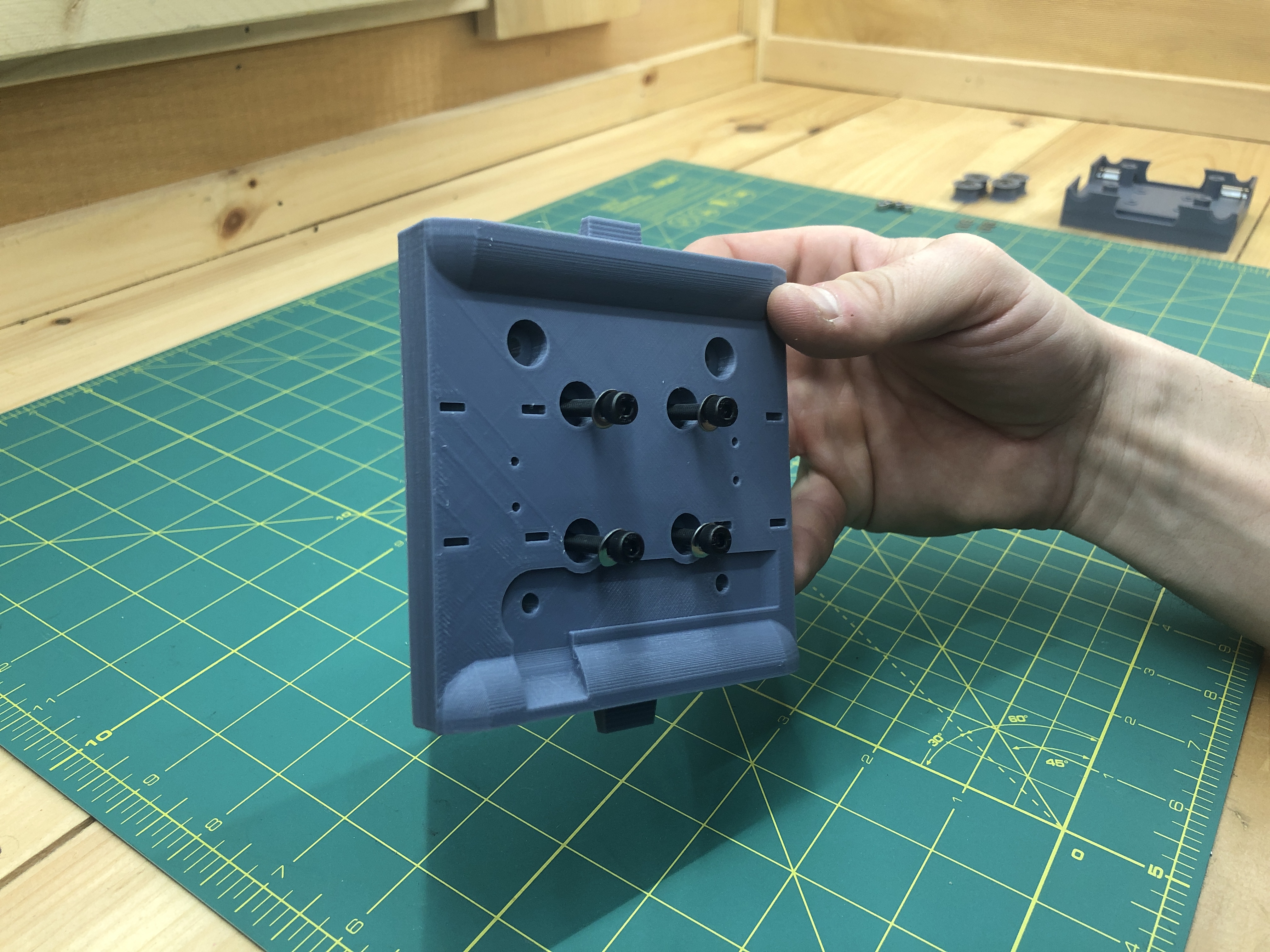
Place it upside down on your work surface.
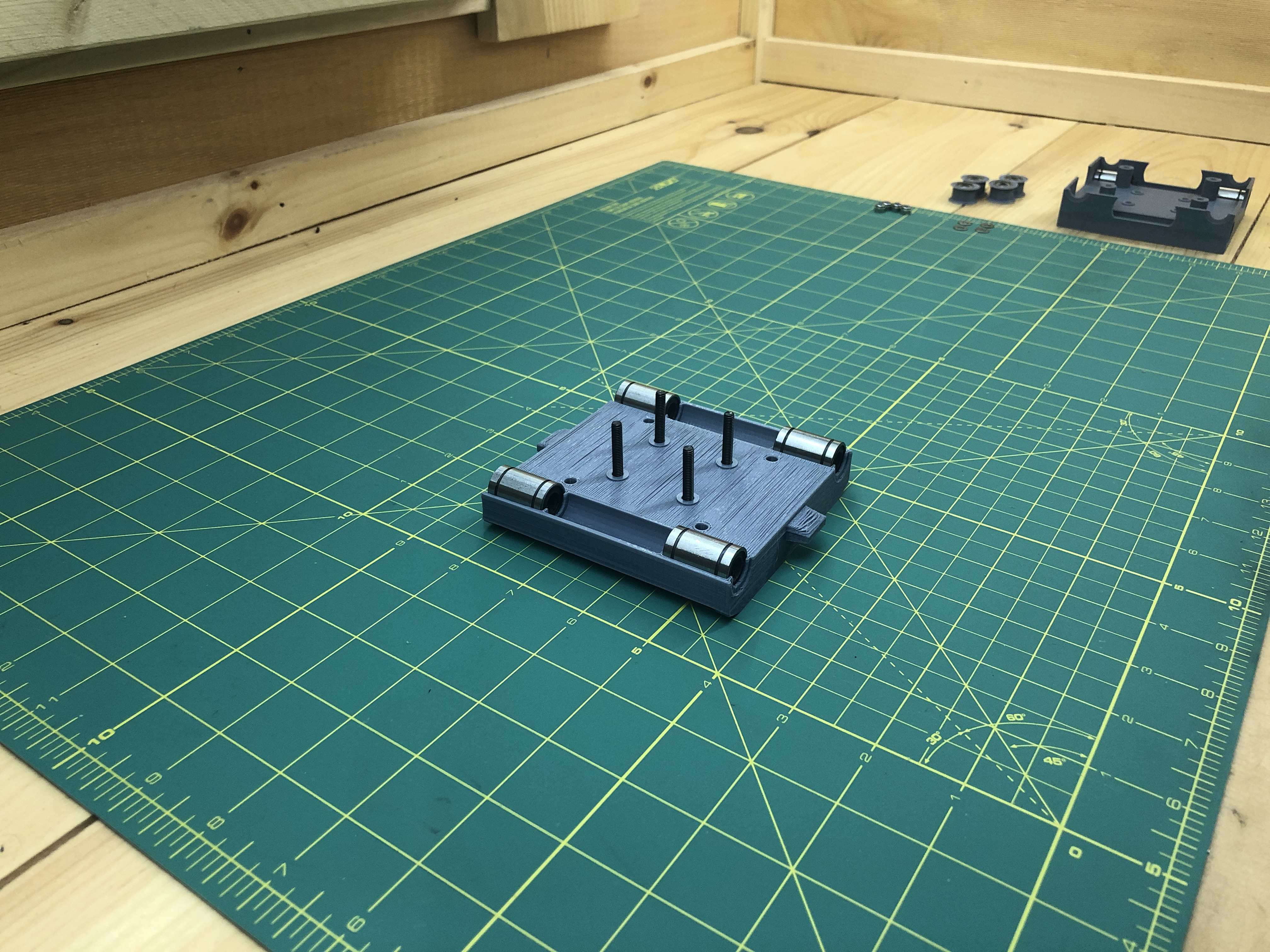
Add 4 belt rollers (we’ll use the 5th later on).
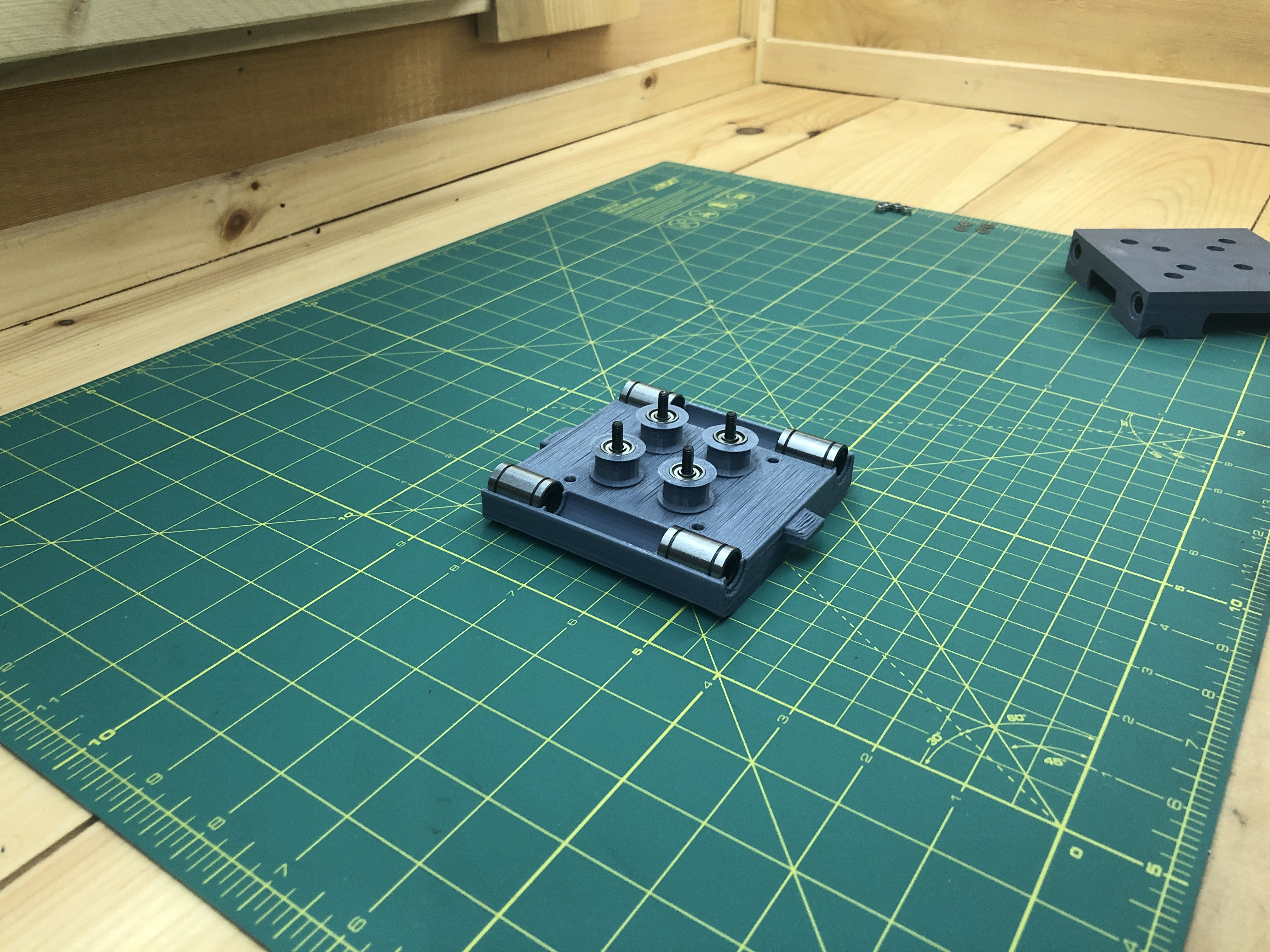
Place the bottom part on top.
Add 4 washers and lock nuts into the innermost holes.

Because we’re going to be handling all this, I like to tape over the 3 nuts I’m not working on so they don’t keep falling. I remove a piece of tape when I’m ready to work on another nut.
Tighten each nut, the operation is a bit tricky, not only because you’re working with a different tool on both side, but also because lock nuts are very tight. Do not tighten the nuts firmly, the screw and its nut should float just a bit. These screws do not hold the gondola together, they only provide an axle for the belt rollers.
Make sure that each belt roller rolls freely inside.
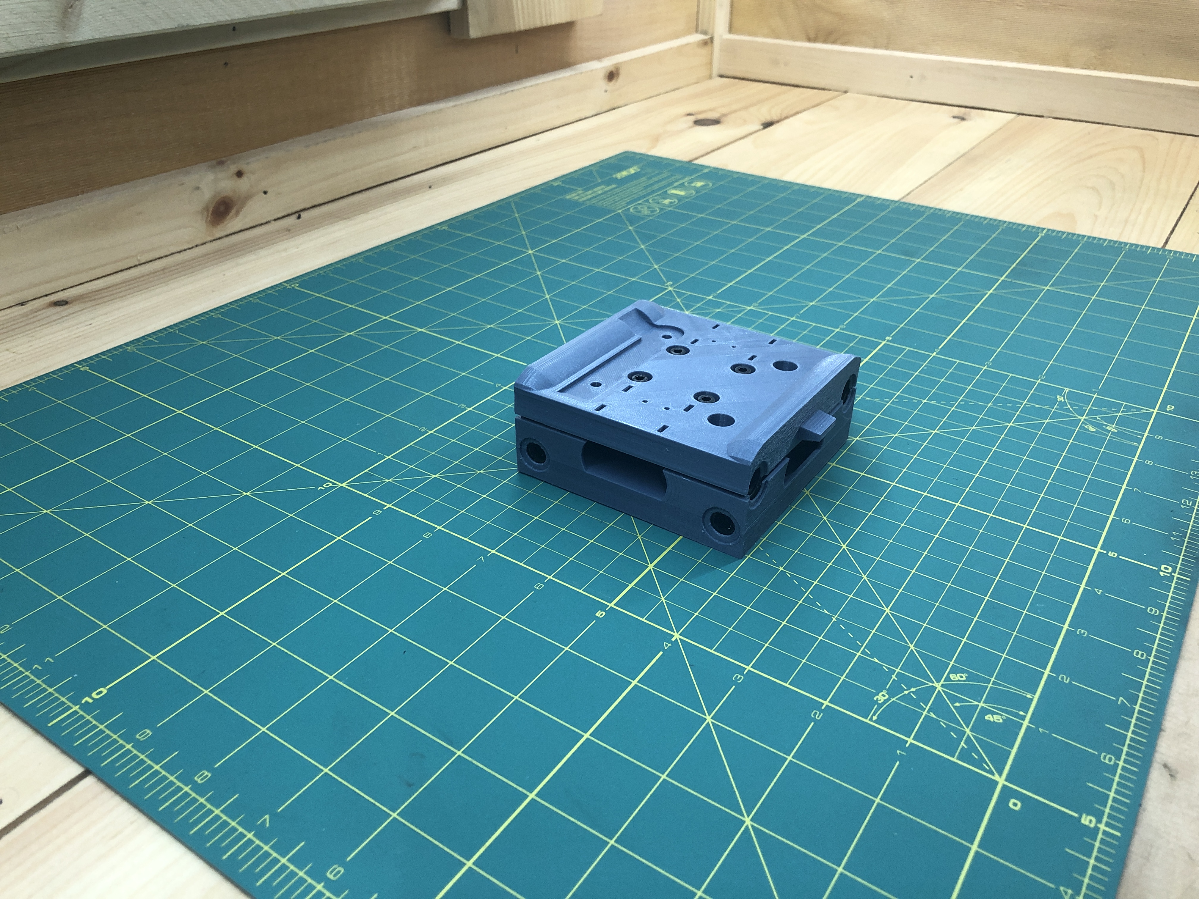
It’ll look this this when you’re done.
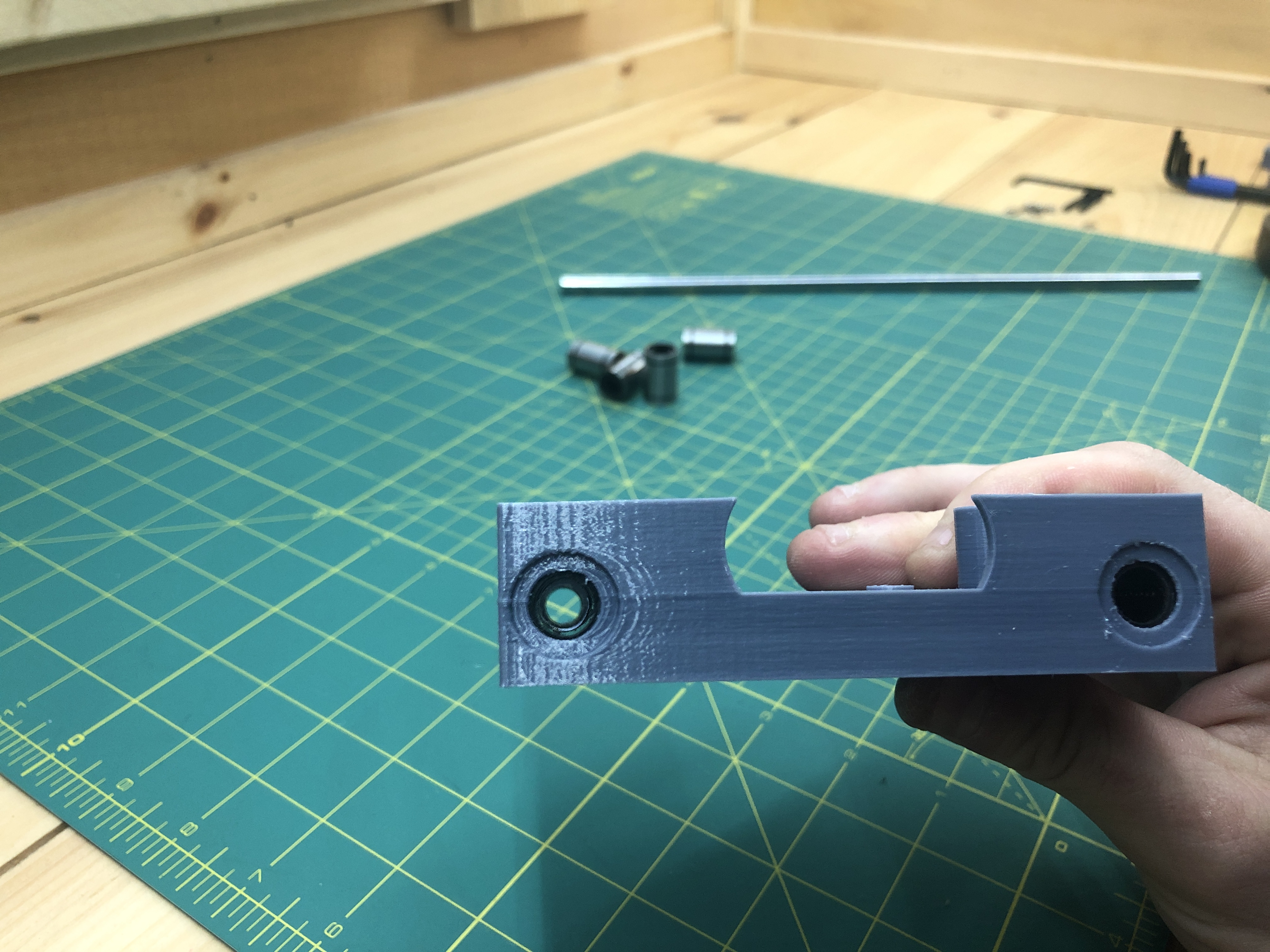
3. Back Assembly Belt Roller
Hardware:
1 M4x35 hex screw
1 M4x25 hex screw
1 M4 lock nut
1 M4 nut
2 washers
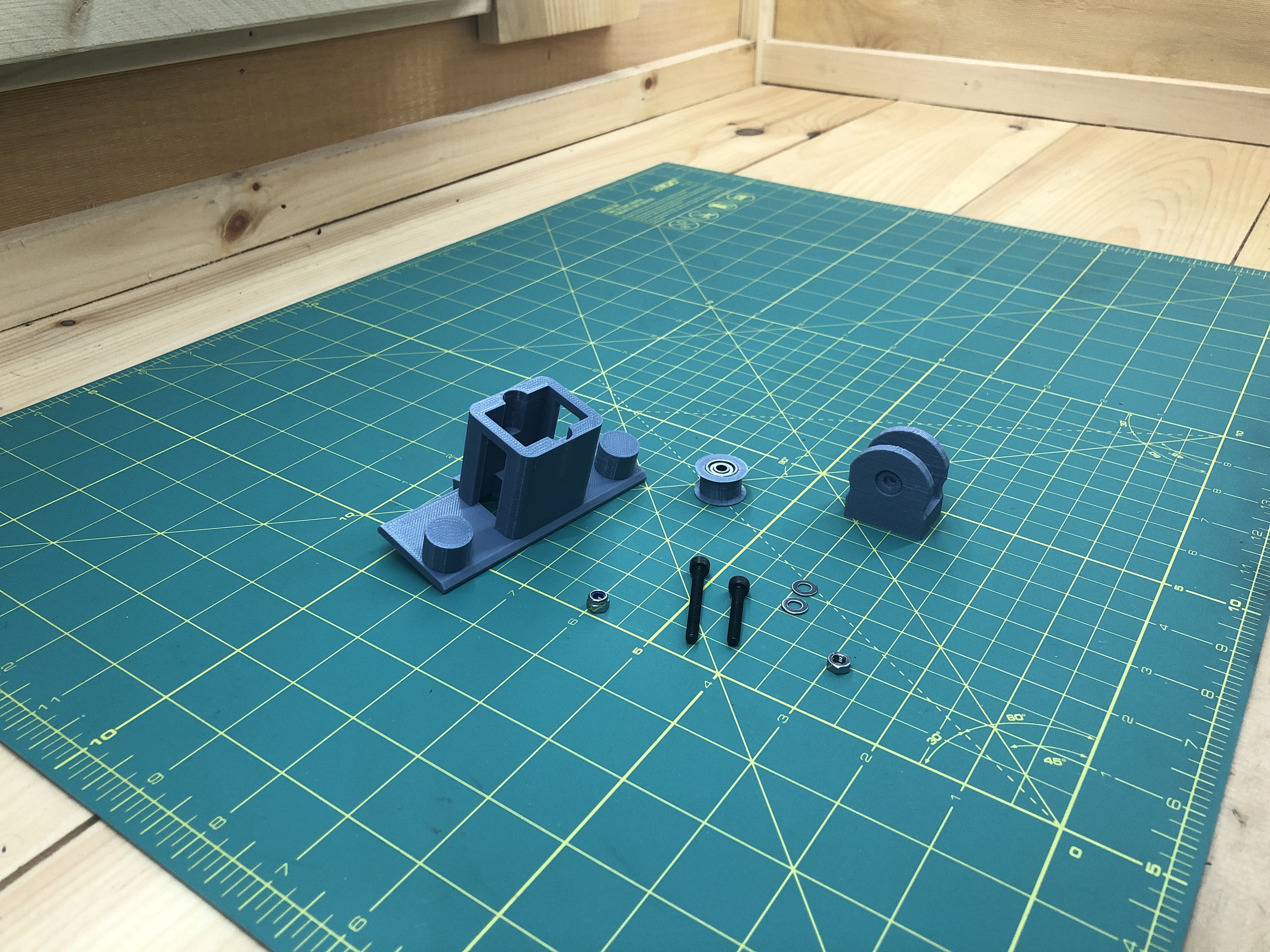
3D Parts:
back_assembly_x1
back_assembly_belt_tightener_x1
We’ll also use the 5th belt roller you made while building the gondola. While we’re doing belt rollers, it make sense to do this part :).
Grab the back assembly, the M4x35 hex screw and the M4 nut. Insert the screw into the hole of the back assembly, screw in the nut on the other side. Then pull the screw to force the nut into its similarly shaped receptacle.

Grab the back_assembly_belt_tightener, put the M4x25 hex screw through it, lock nut on the other side and washers on both sides.
As with the gondola, do not overtighten the roller, this is only an axle. Make sure the belt rolls freely.
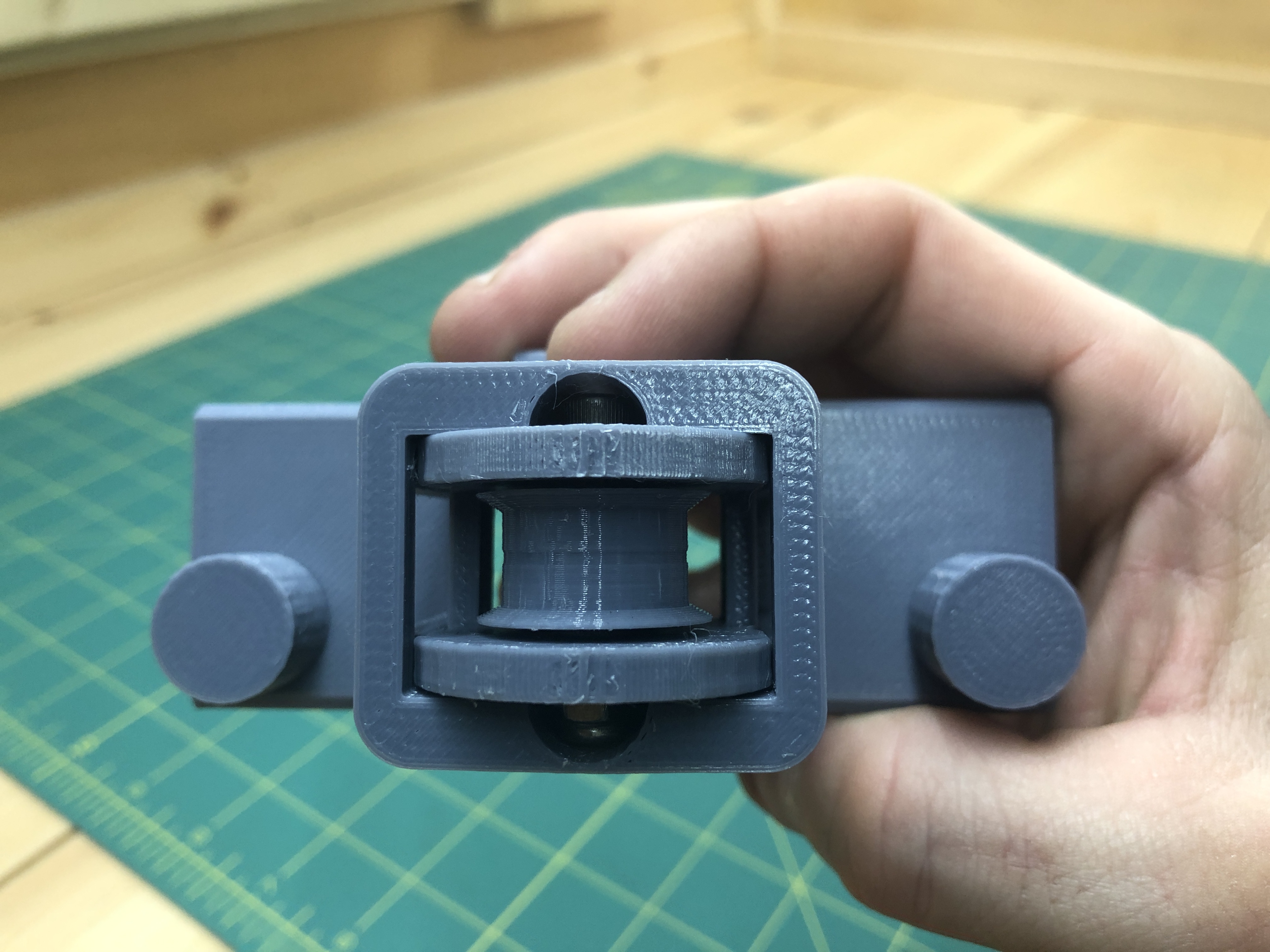
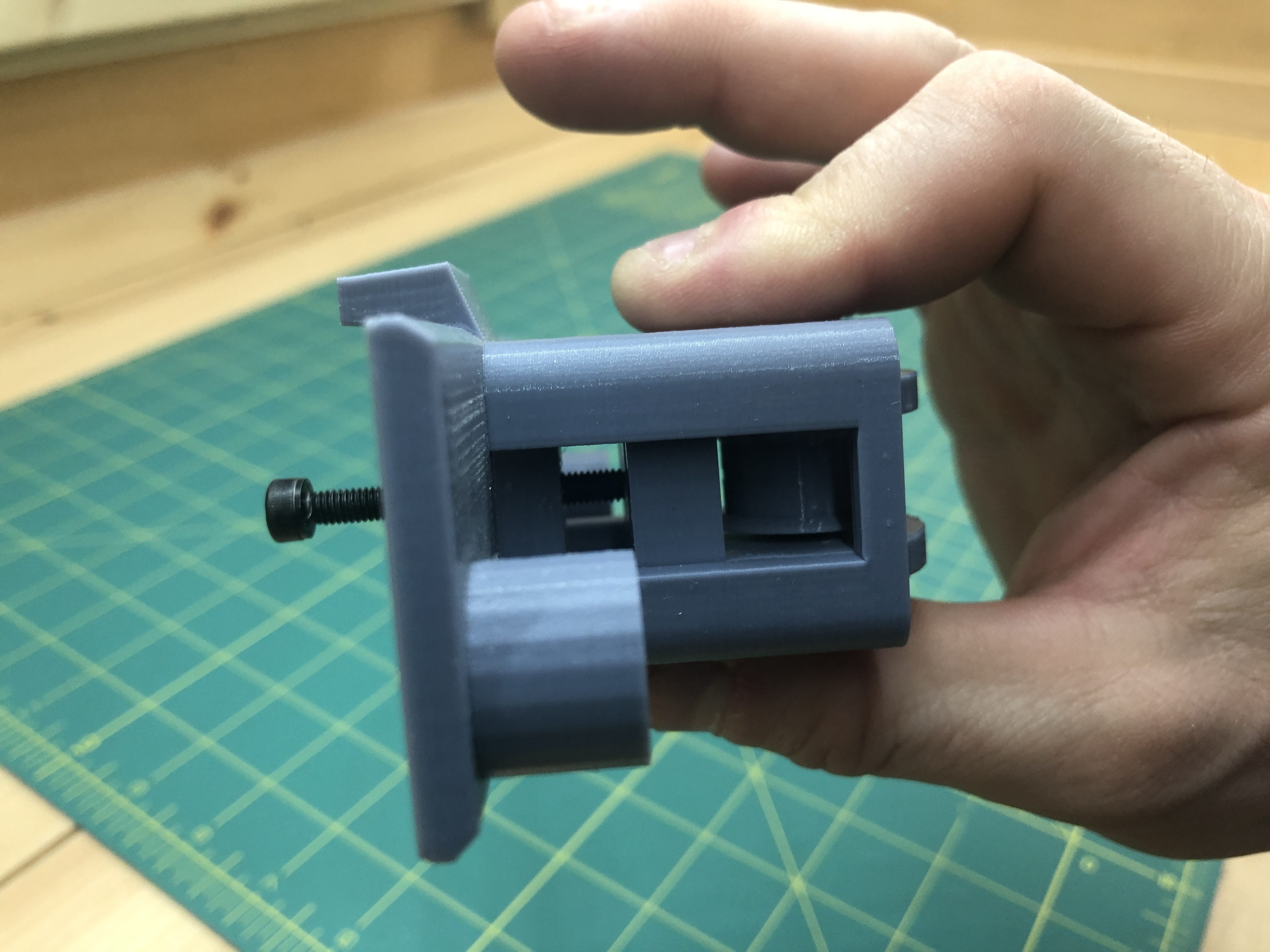
You’ve built both parts.
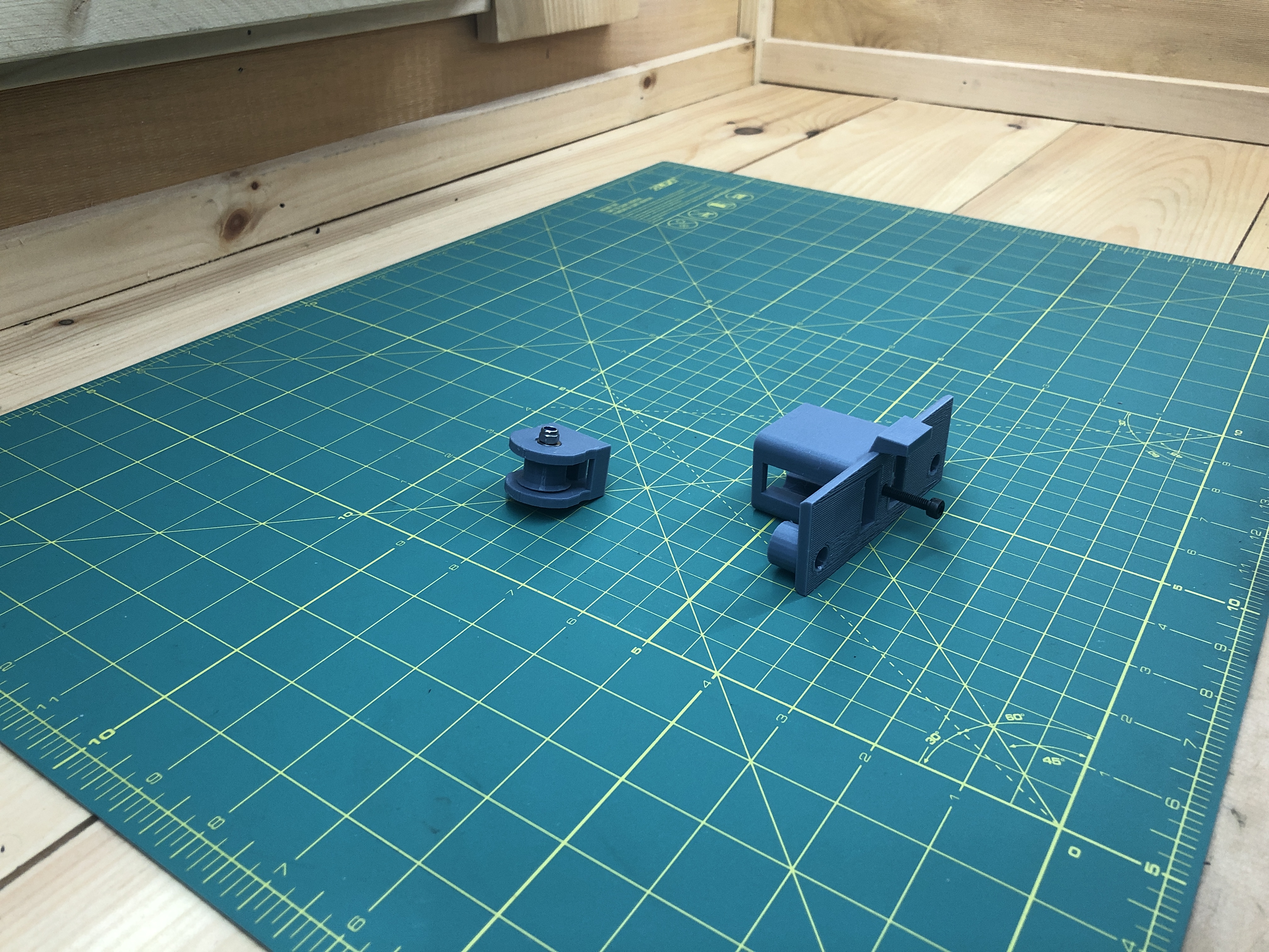
Now we put them together. One simply fits into the other as follows.
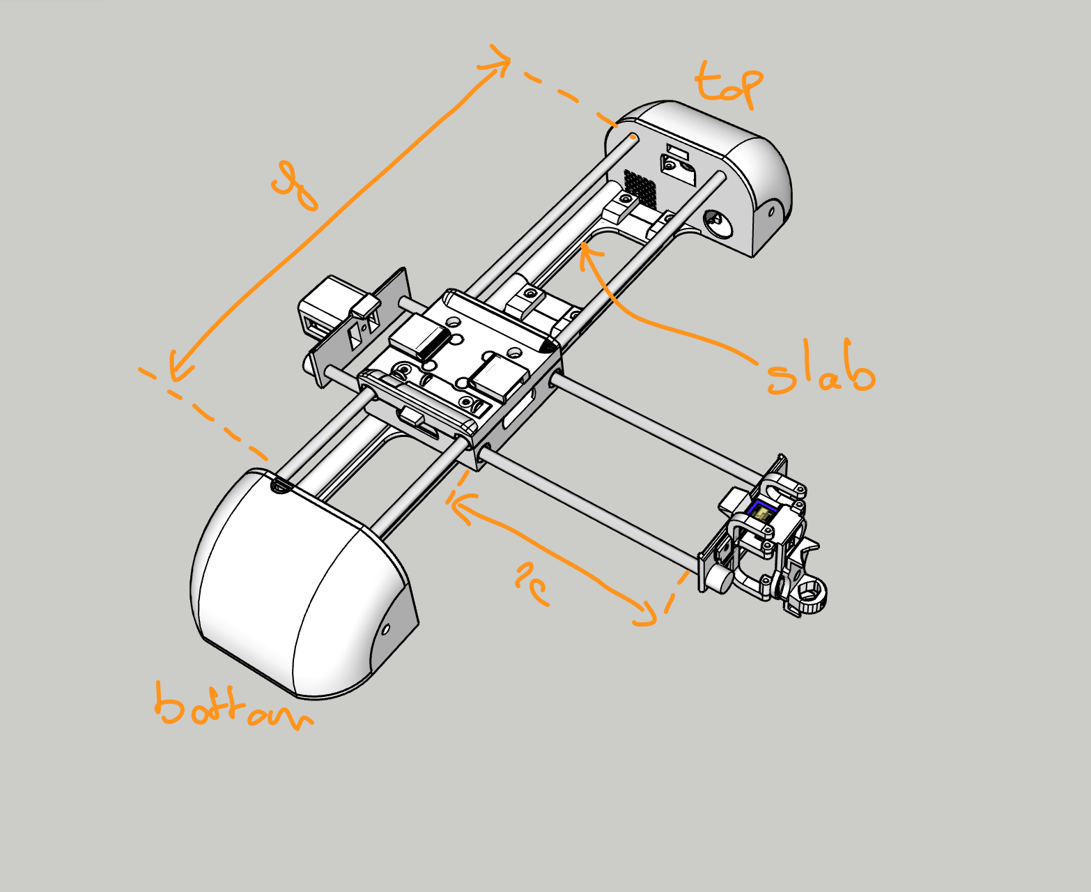
3. Main frame, the Y axis
Hardware:
8 M4x12 hex screw
12 M4 nuts
8 washers
2 M4x30 hex screws
2 linear rod 8x450mm
3D Parts:
terminal_joining_slab_x3
terminal_bottom_x1
terminal_top_x1
terminal_height_adjust_foot_x2
Electric:
a whole bunch of wires
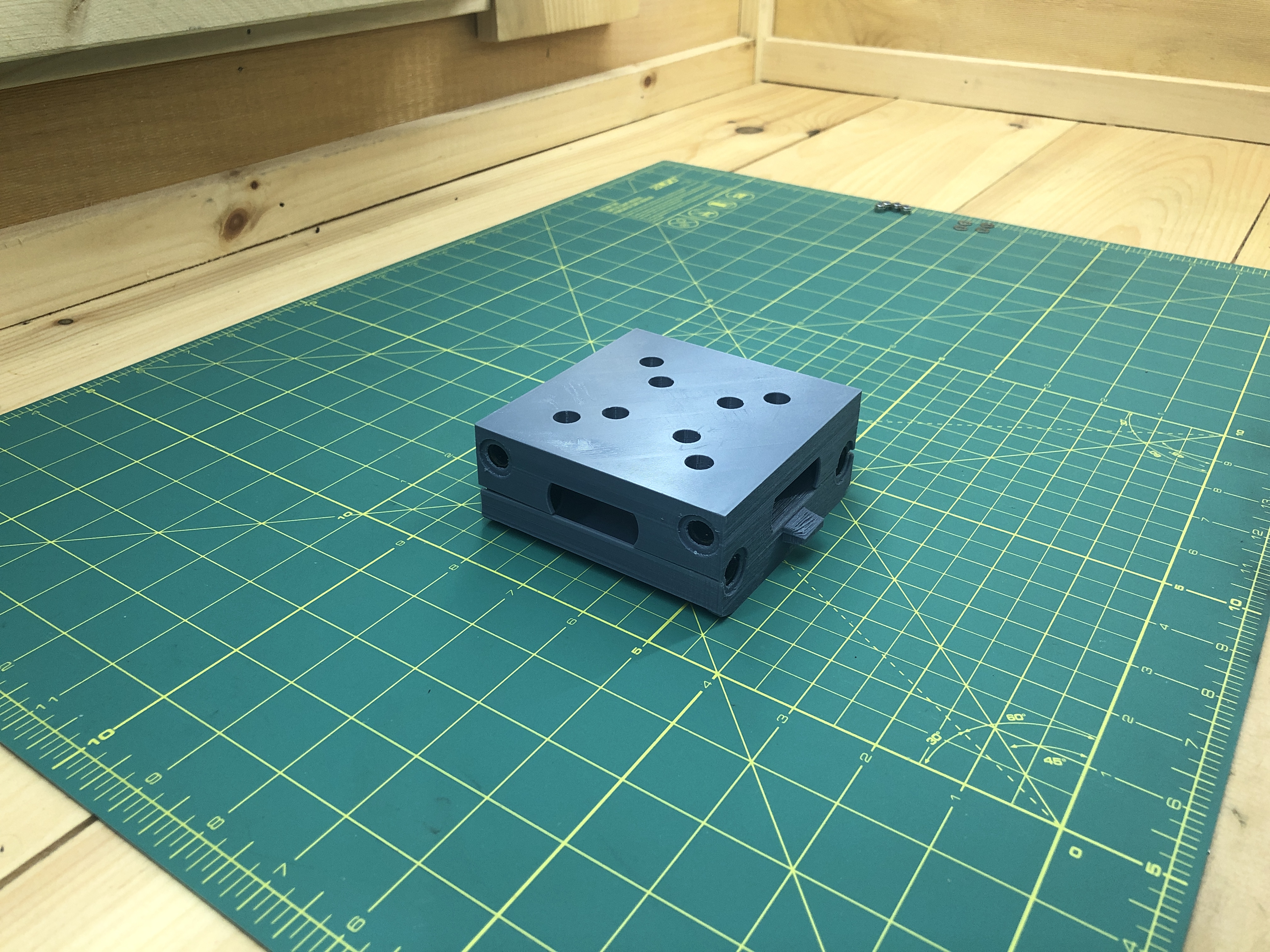
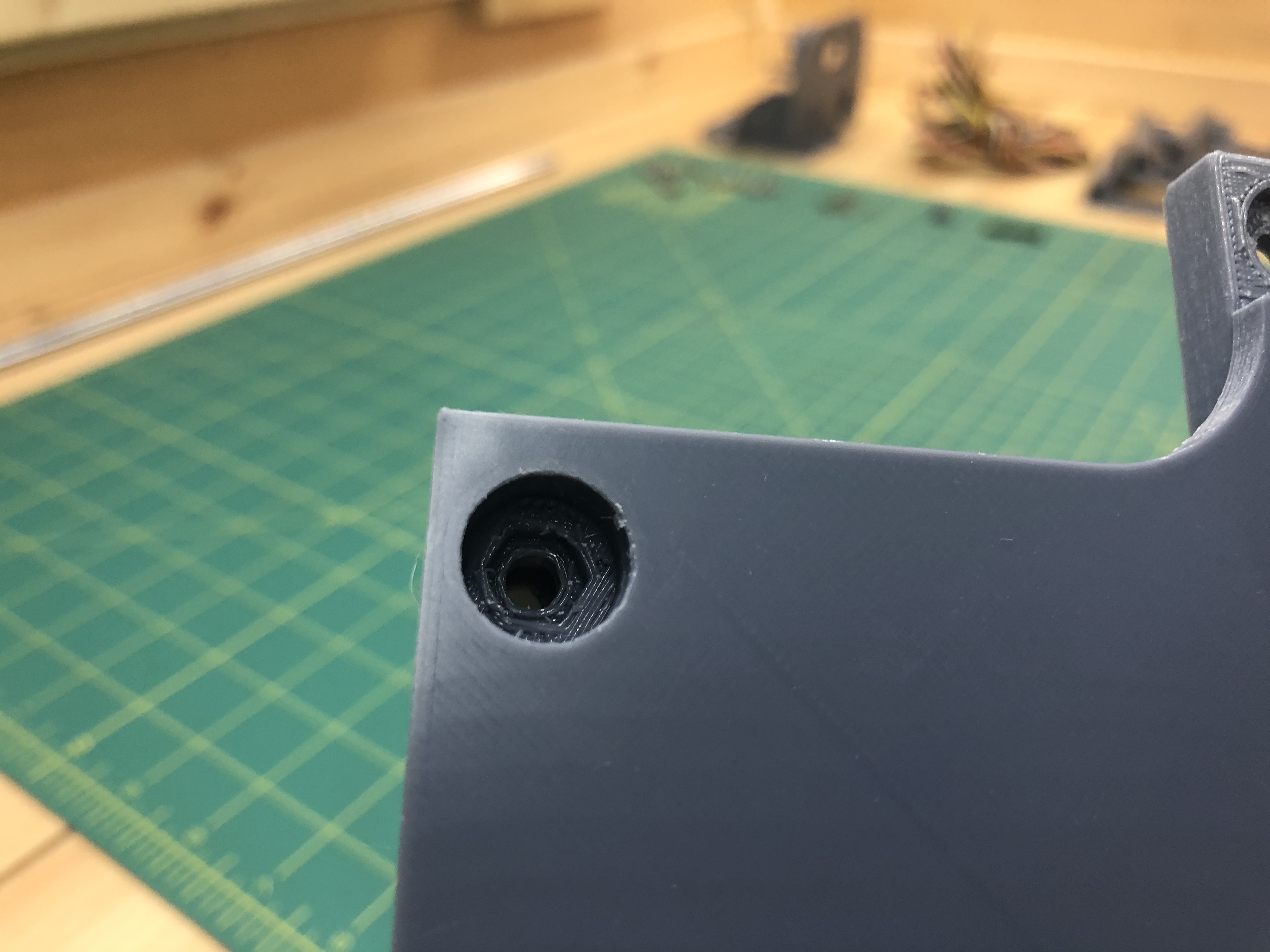
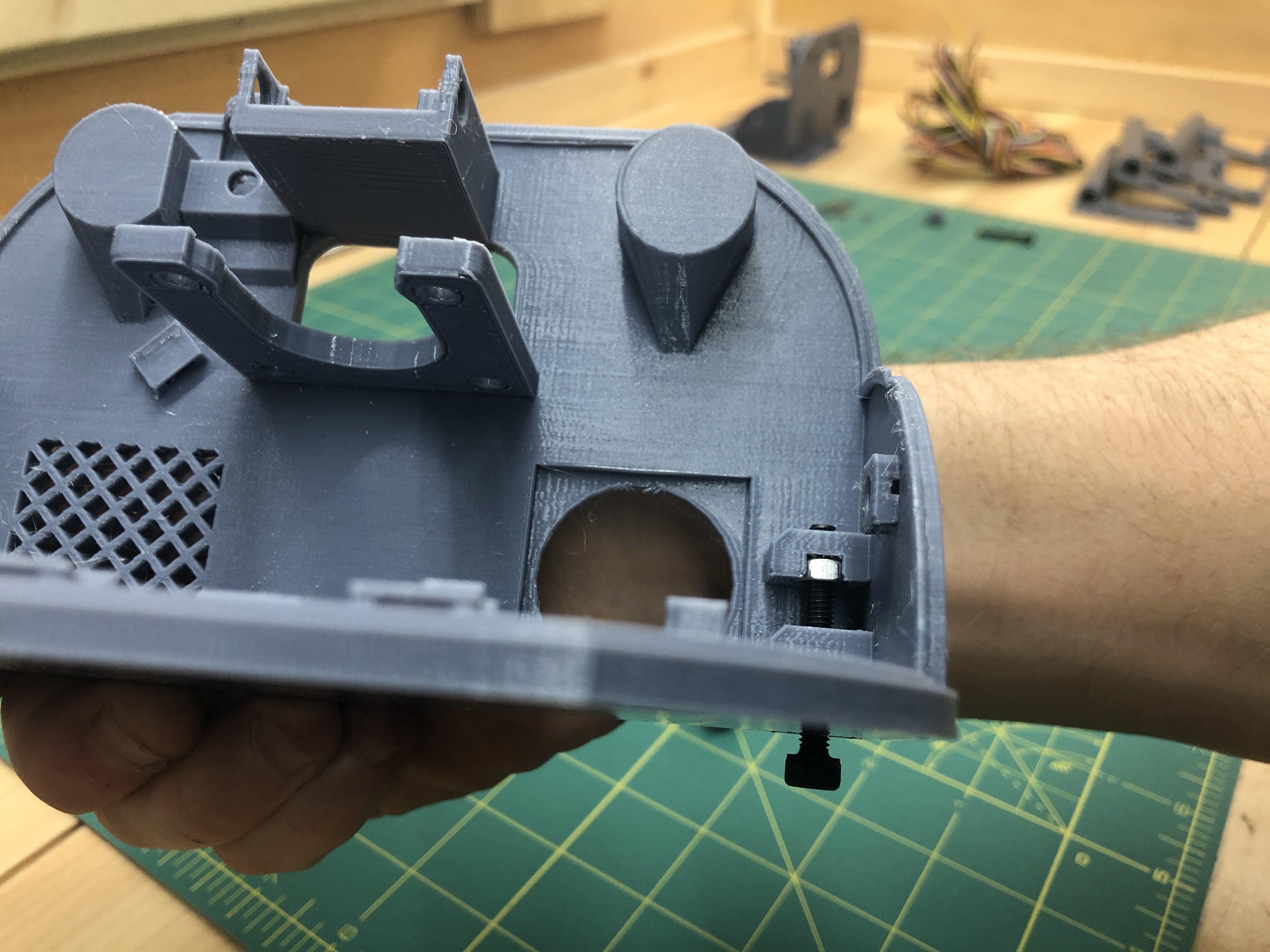
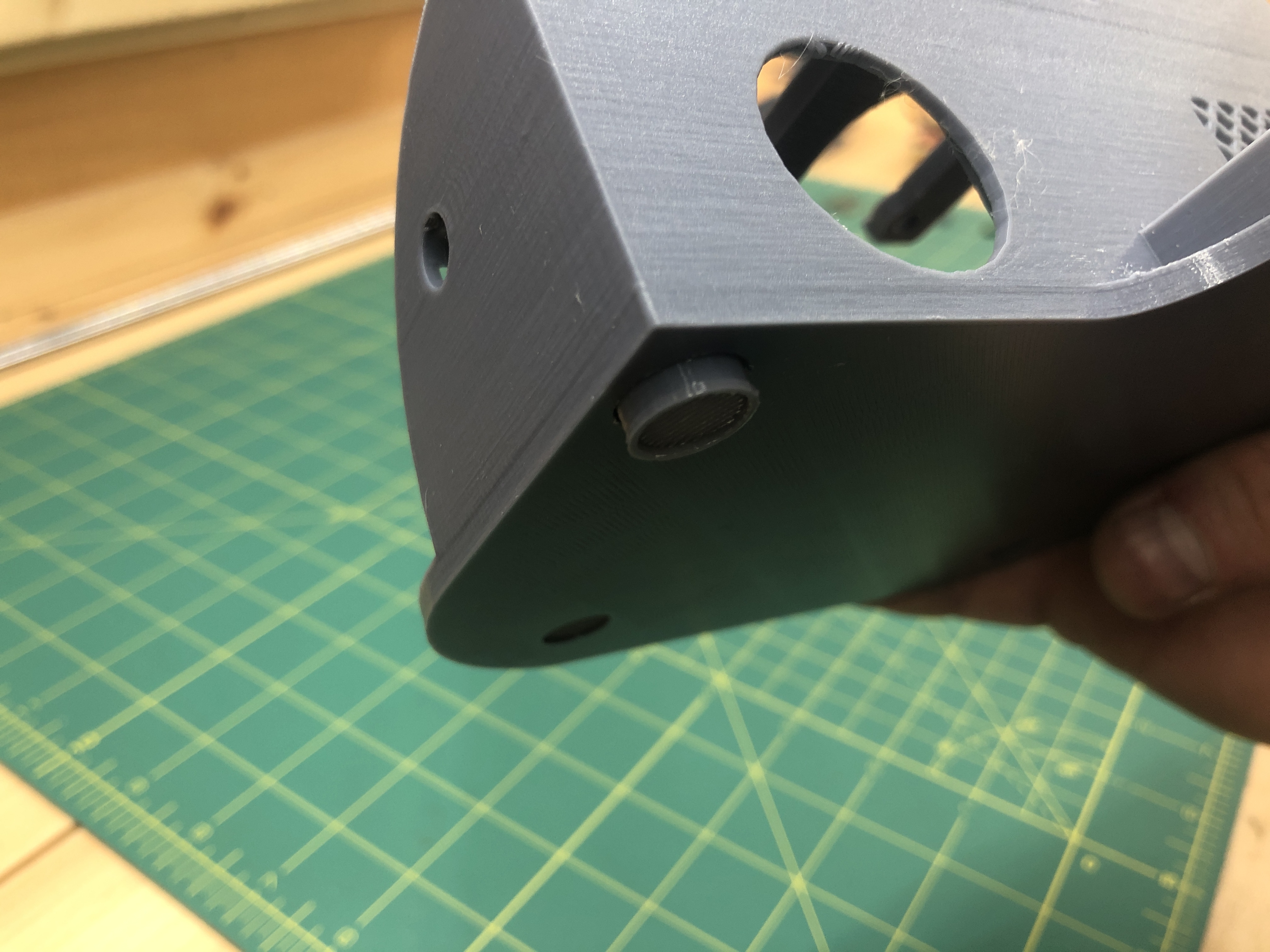
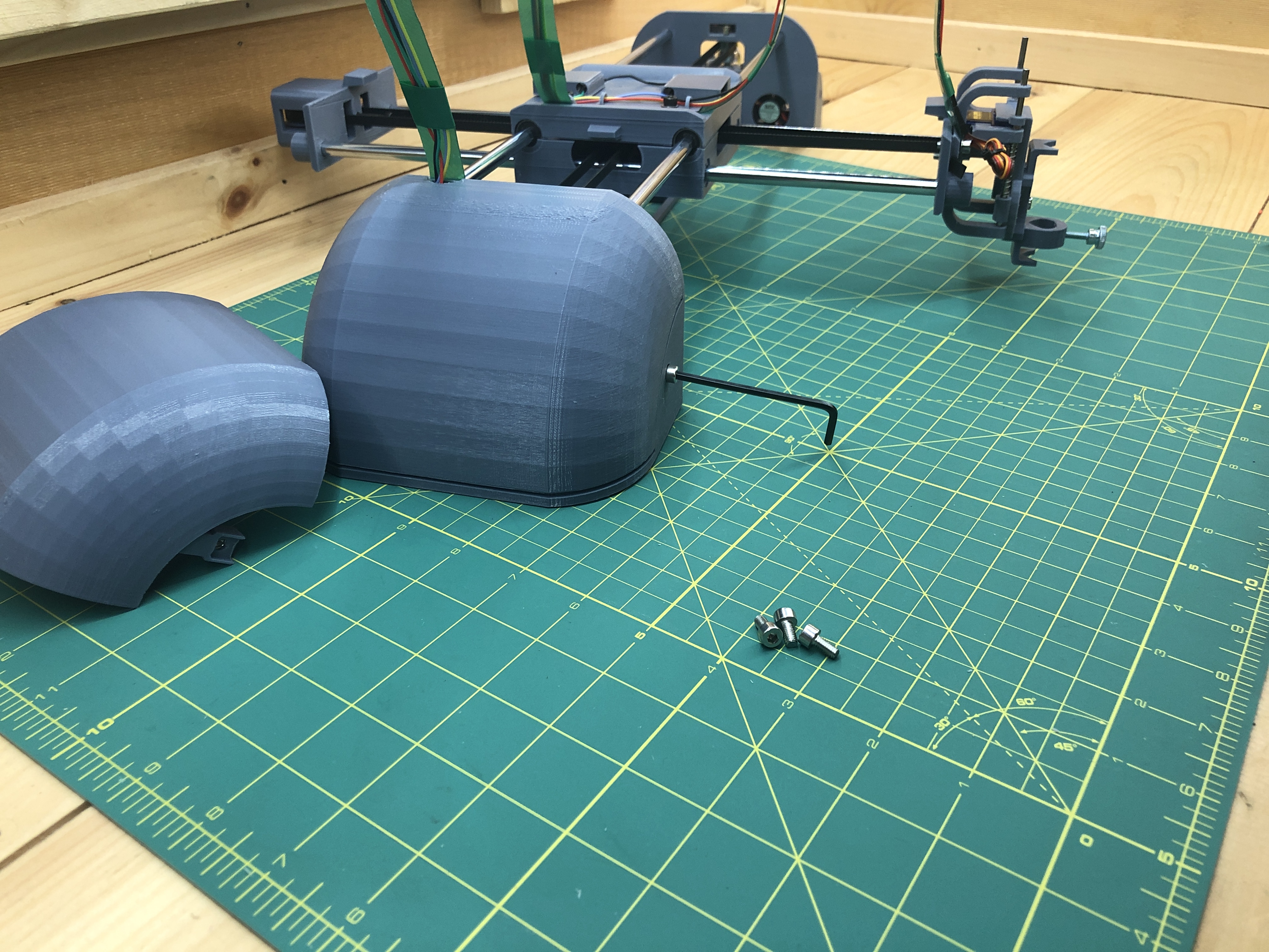
In the corner of both terminal_top and terminal_bottom, you’ll find the following:
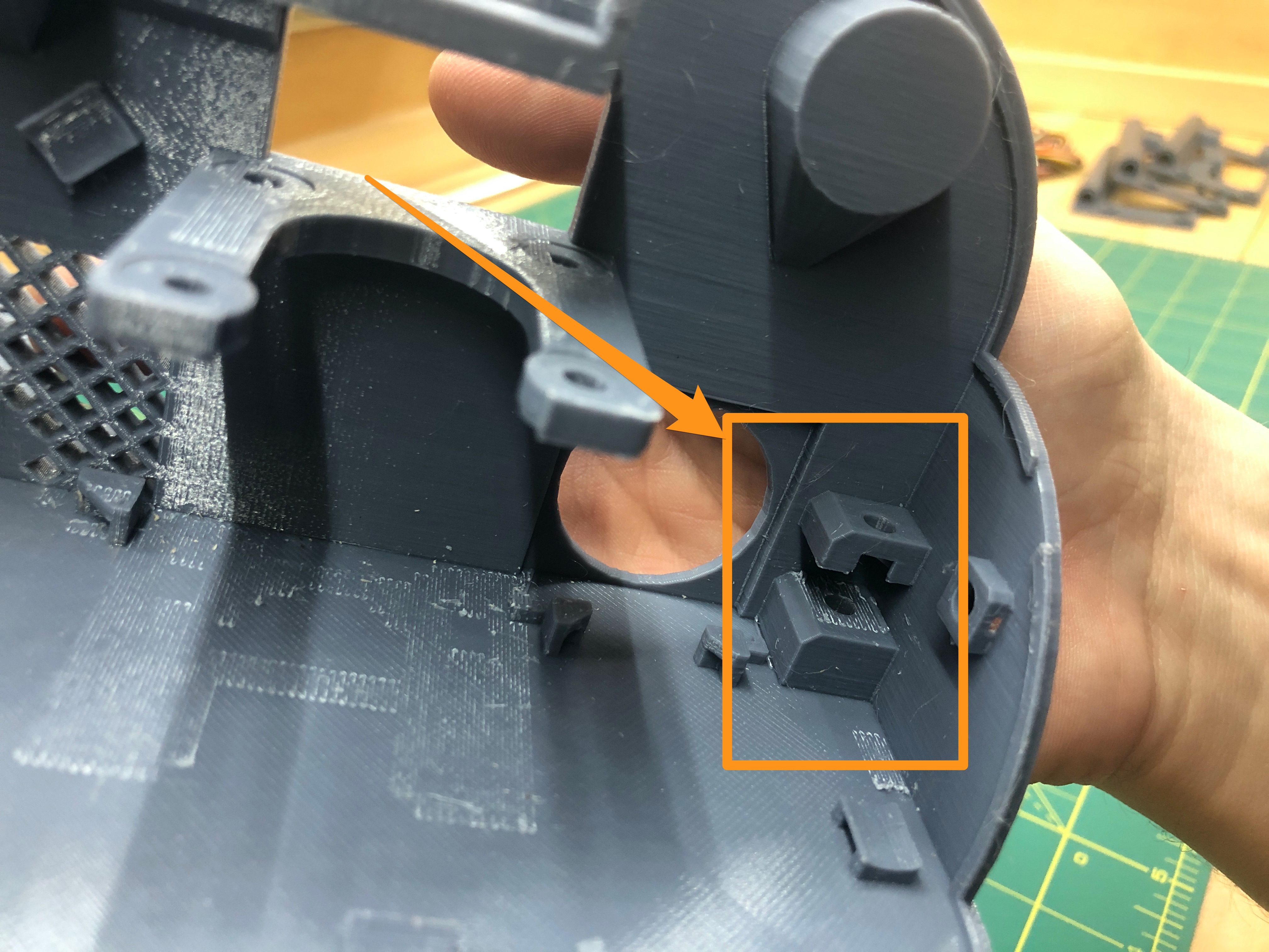
It’s a oddly shaped assembly meant to receive 2 nuts and a screw to serve as height adjusters for your plotter. On the bottom of the terminal, where is assembly is, is a hole for a M4x30 hex screw and a receptacle for an M4 nut.
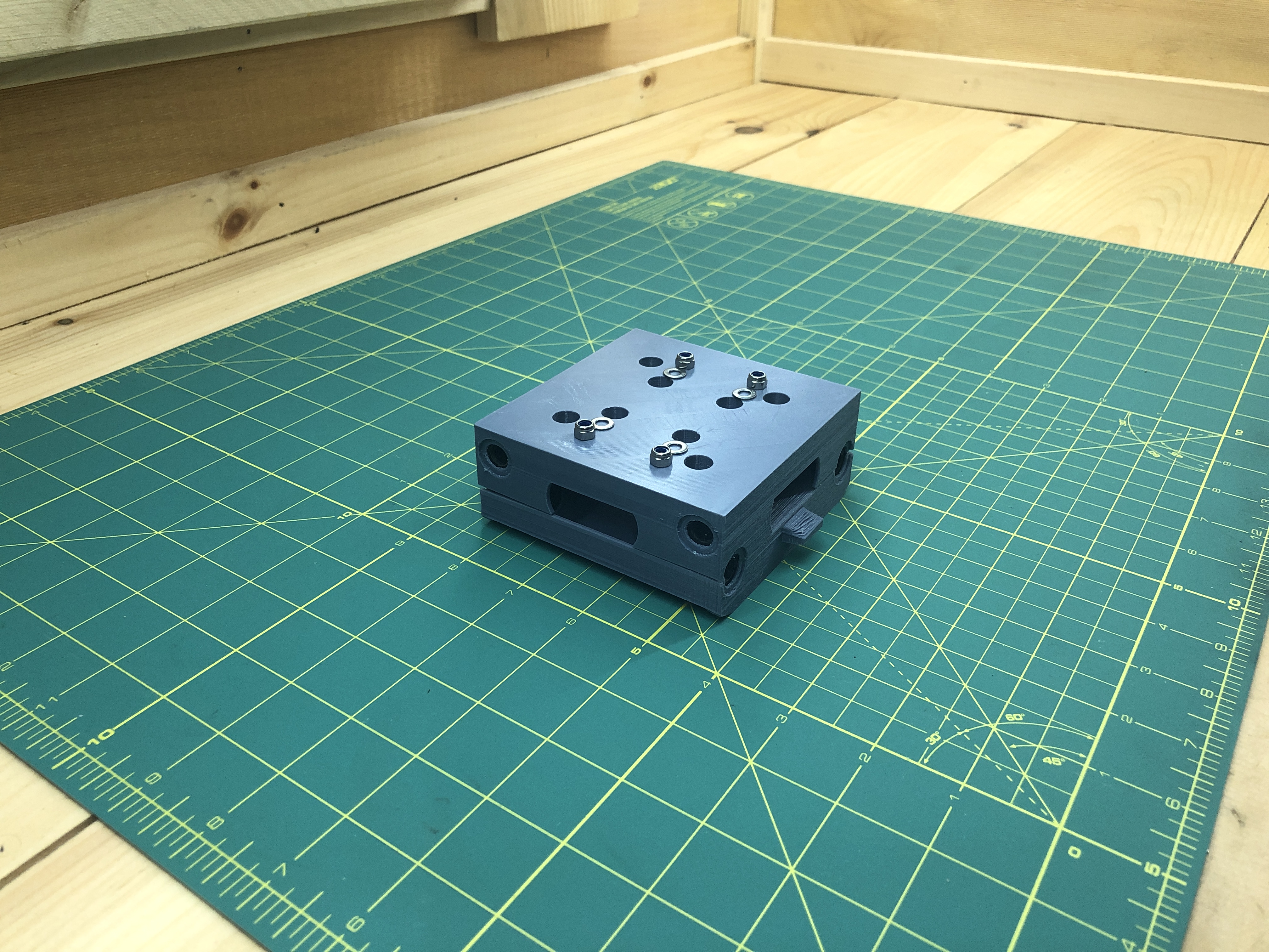
Screw the nut on the screw.

Then pressure fit it in the bottom receptacle.
Screw into the terminal until you can see the screw.
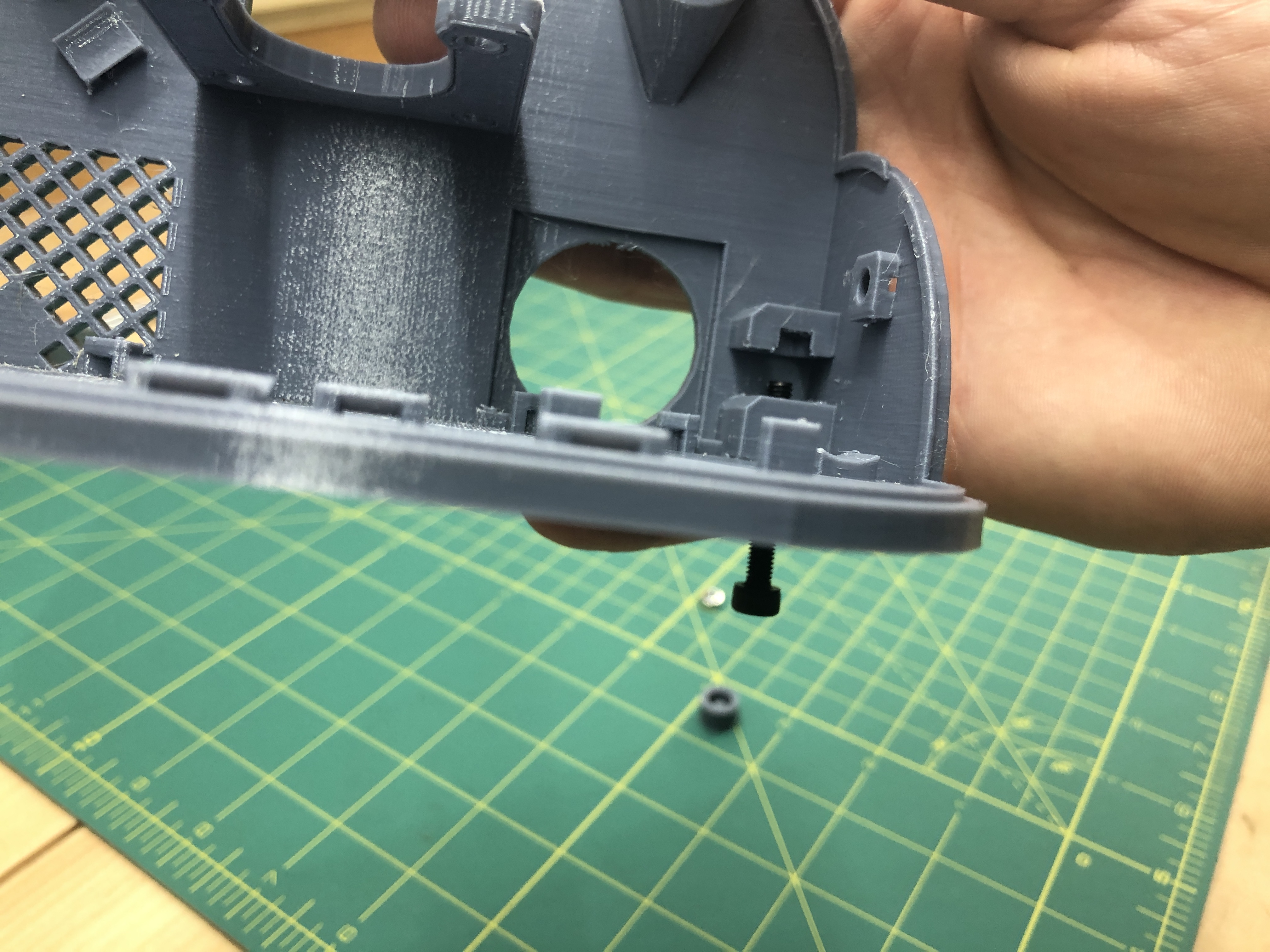
Then add another nut.
Then screw in some more until the nut you just added is itself pressure fitted into the receptacle above it. This is a bit of a funny exercise which takes a bit of back and forth to figure out.

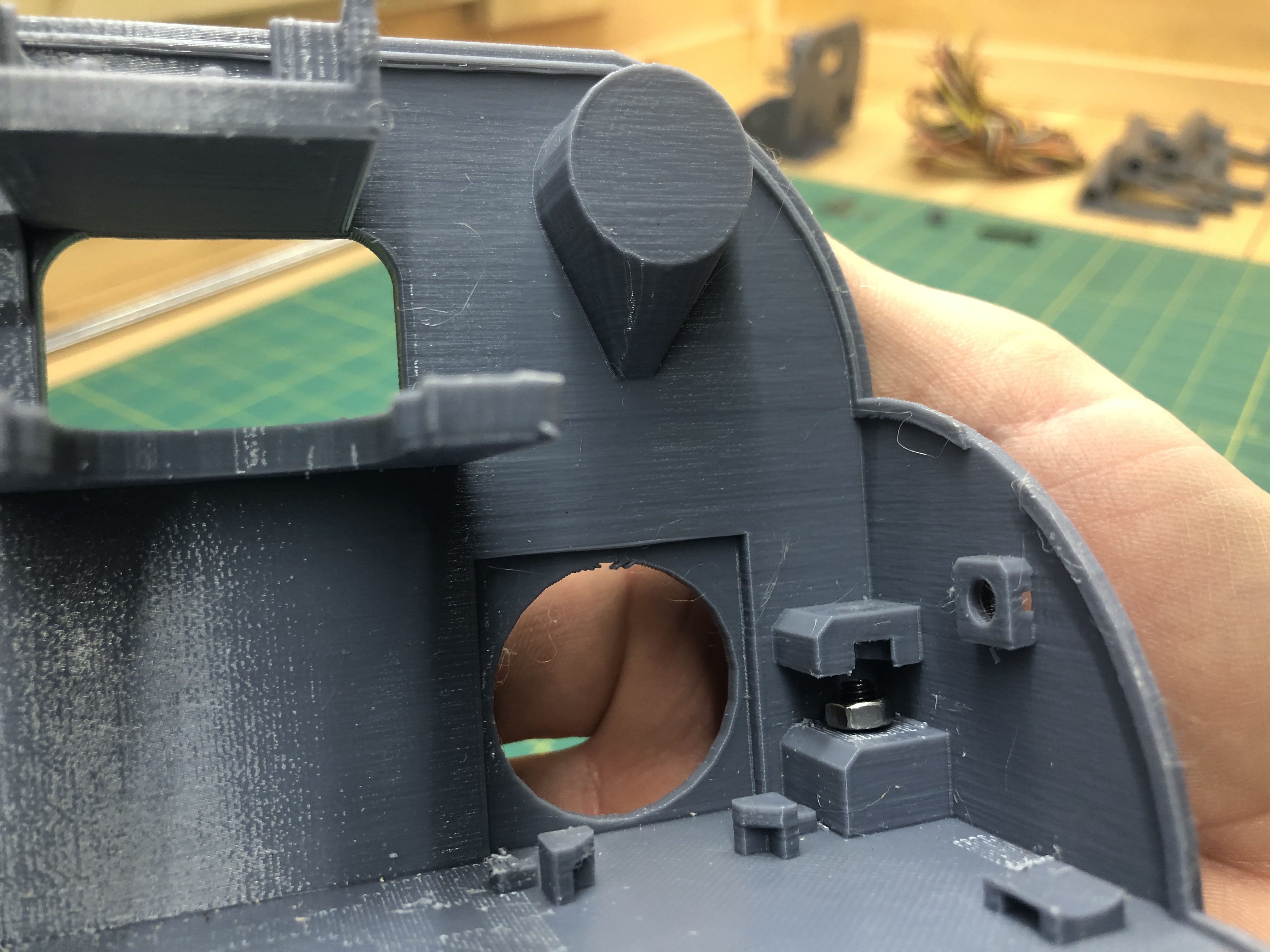
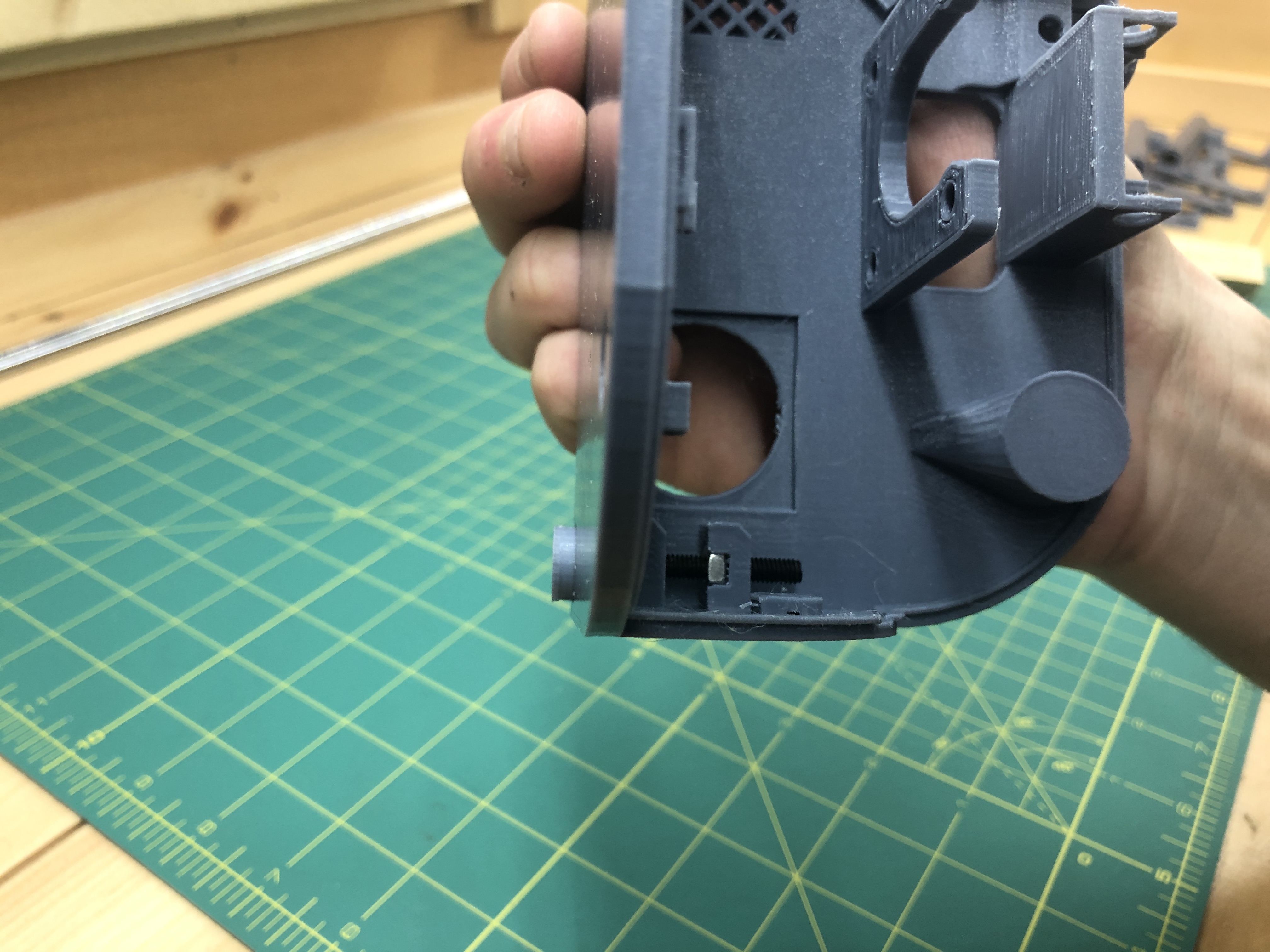
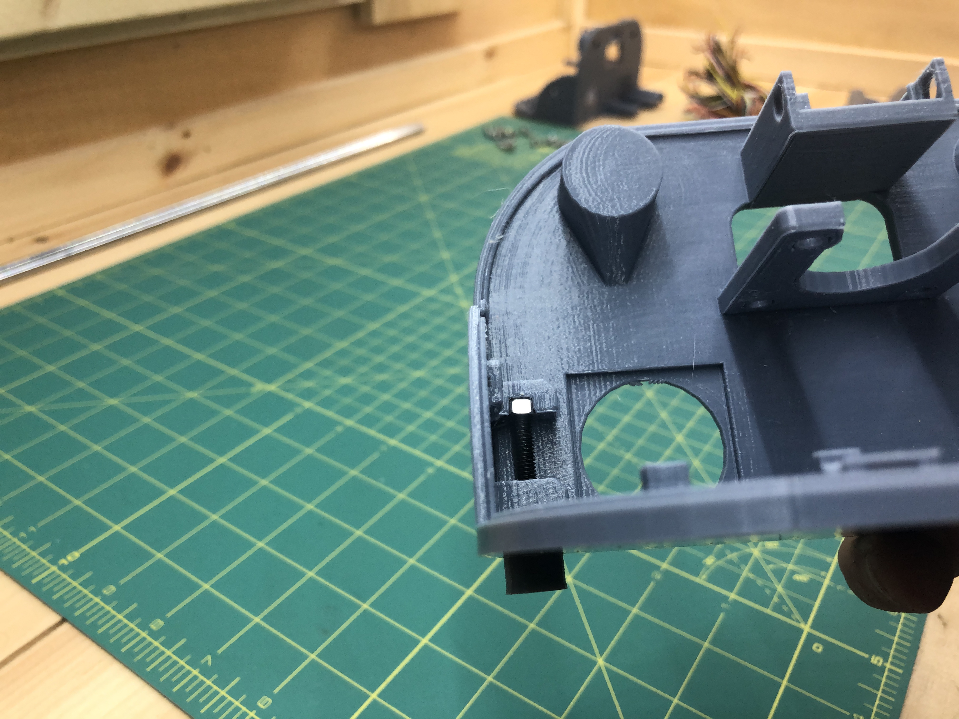
When you’re done you have a screw held by 2 firmly encased nuts.
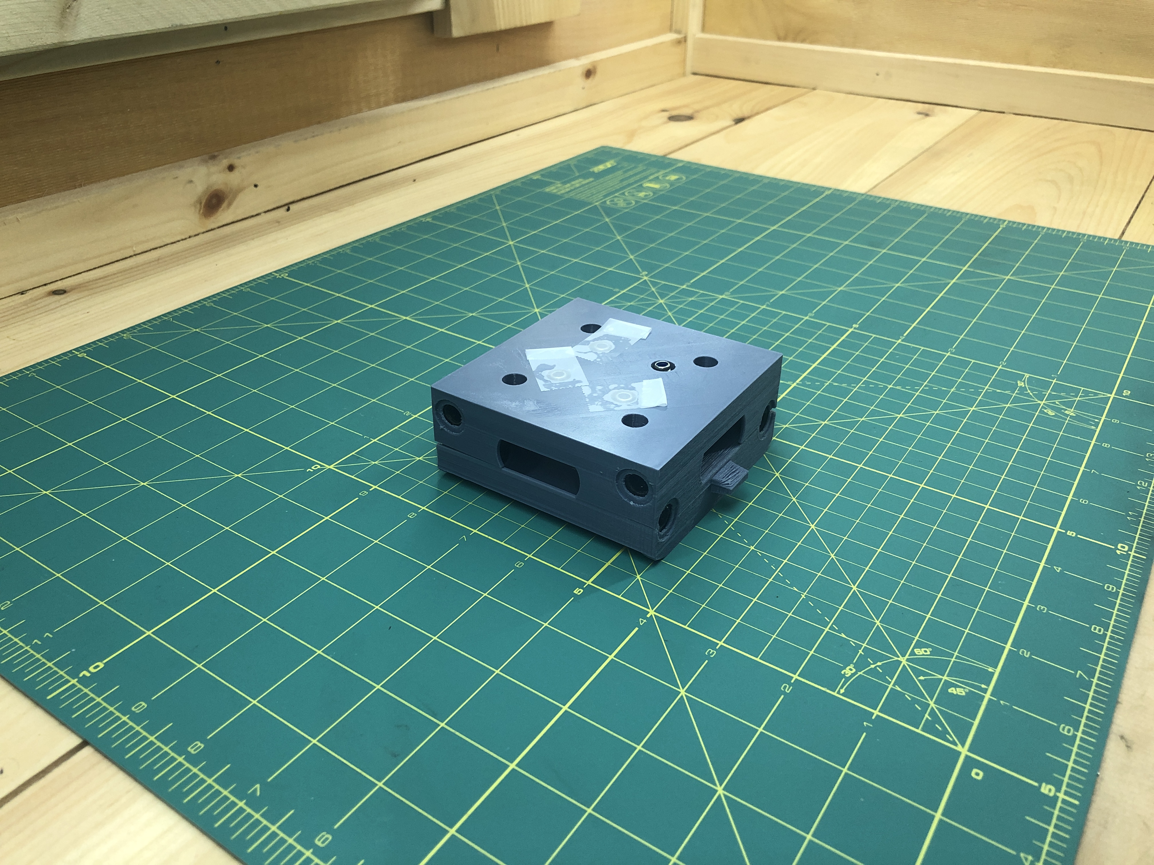
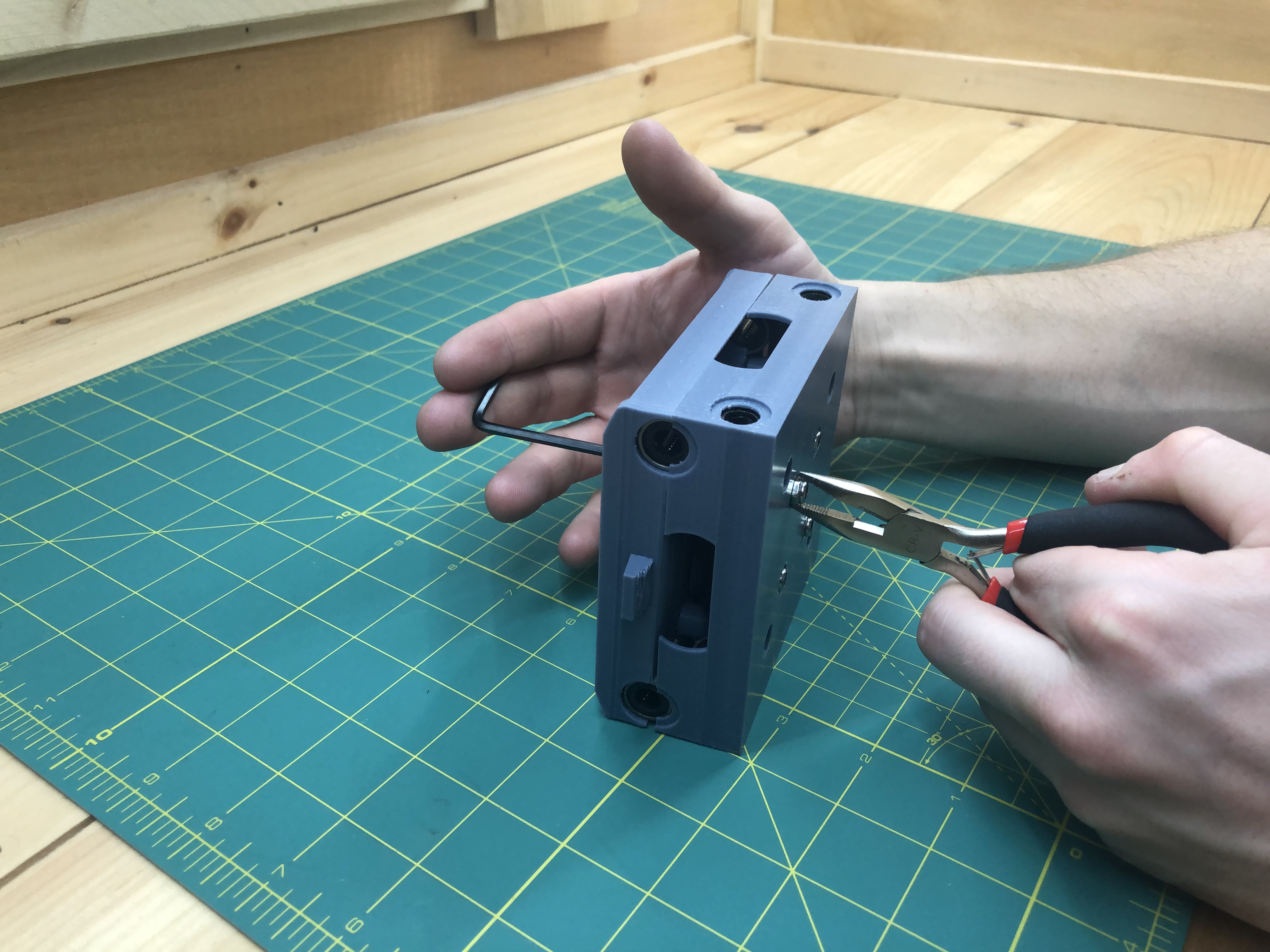
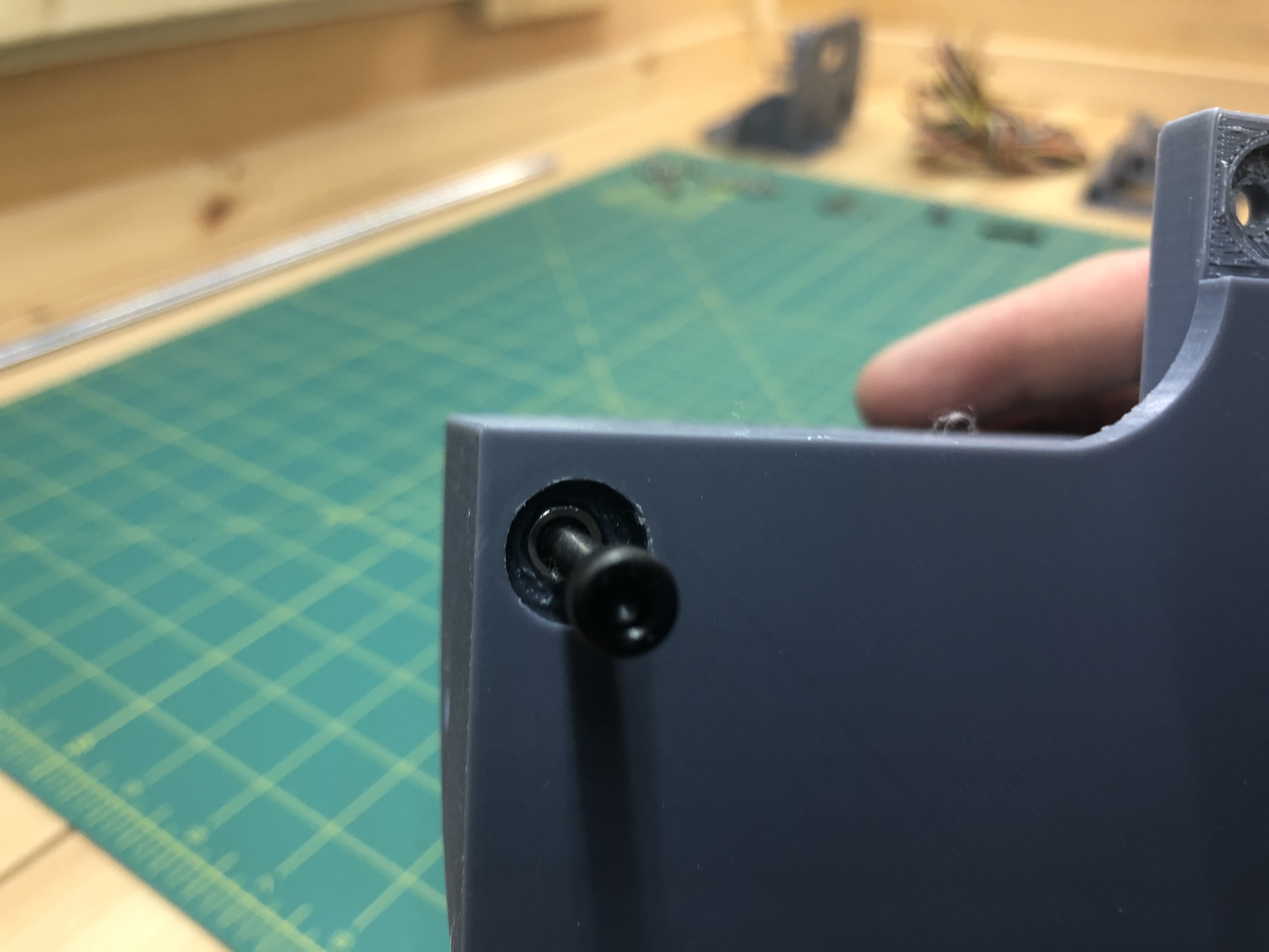
Put super glue into a terminal_height_adjust_foot end where a hex head is meant to fit a screw head.
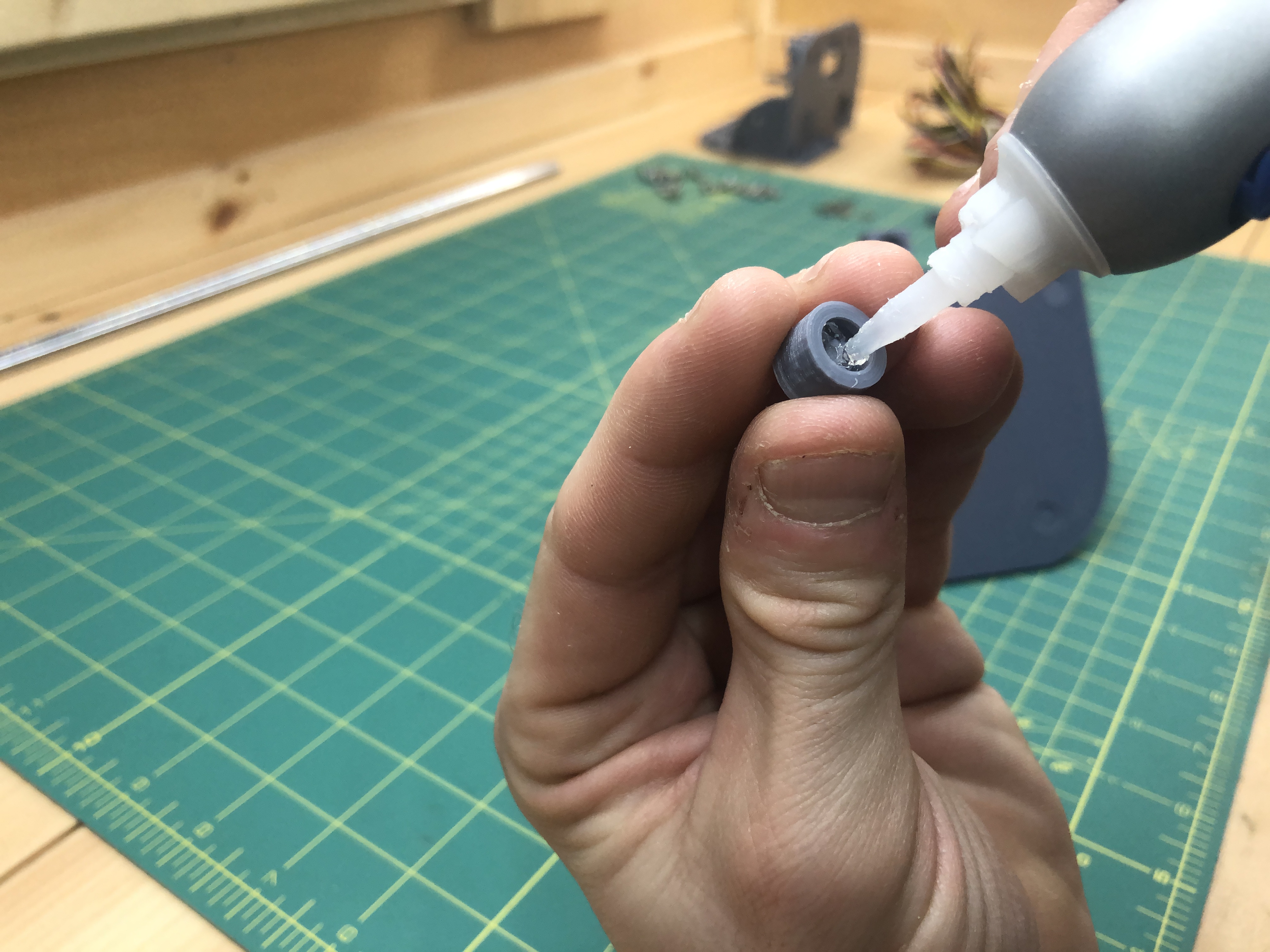
Then pressure fit it into the screw. The gentle hammering may come in handy. I took the screw out precisely for this :).
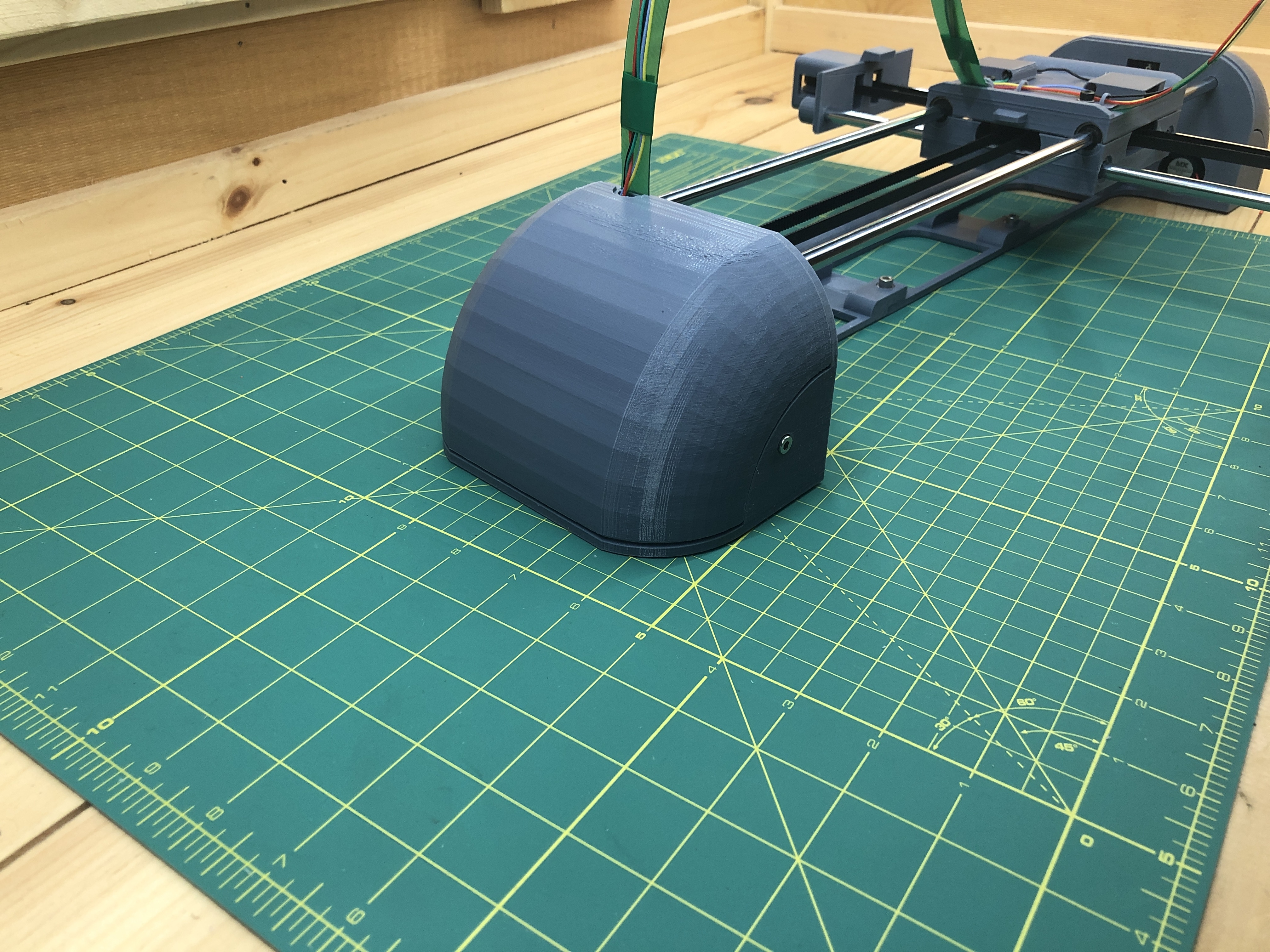
Put the screw back in, you now have a height adjustable foot on your terminal.
Do the same for the other terminal, I’ll skip all the known steps.
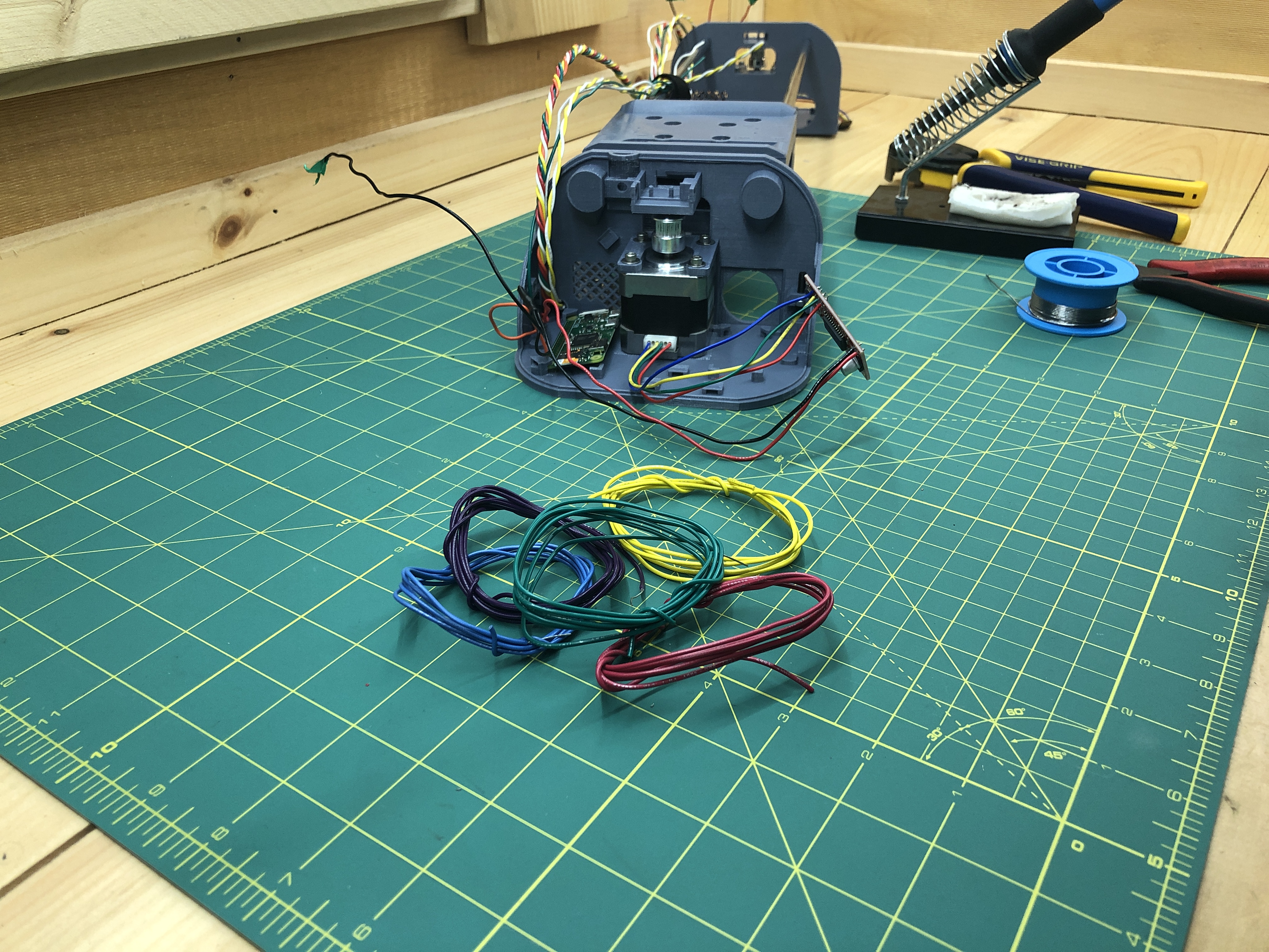
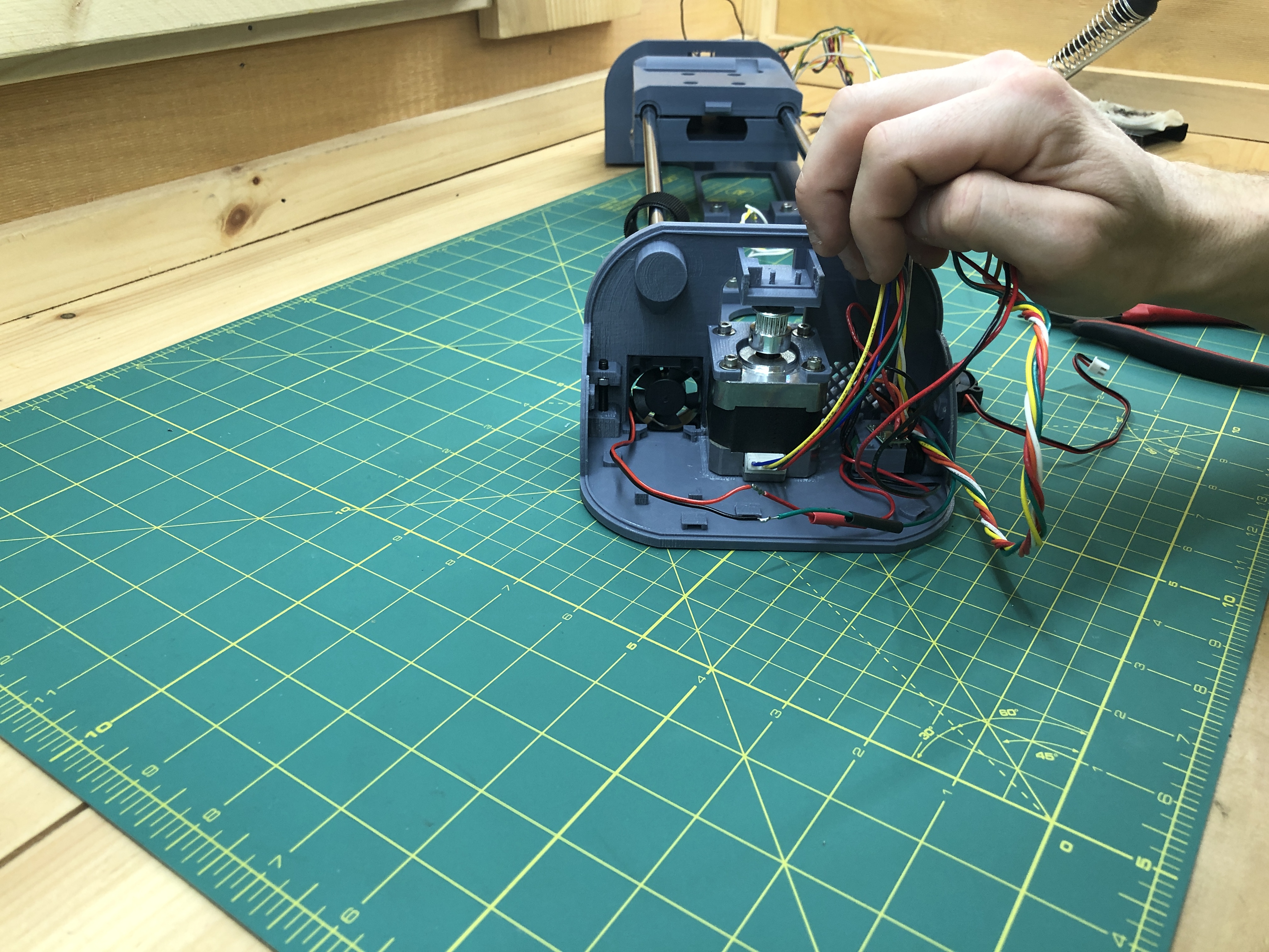
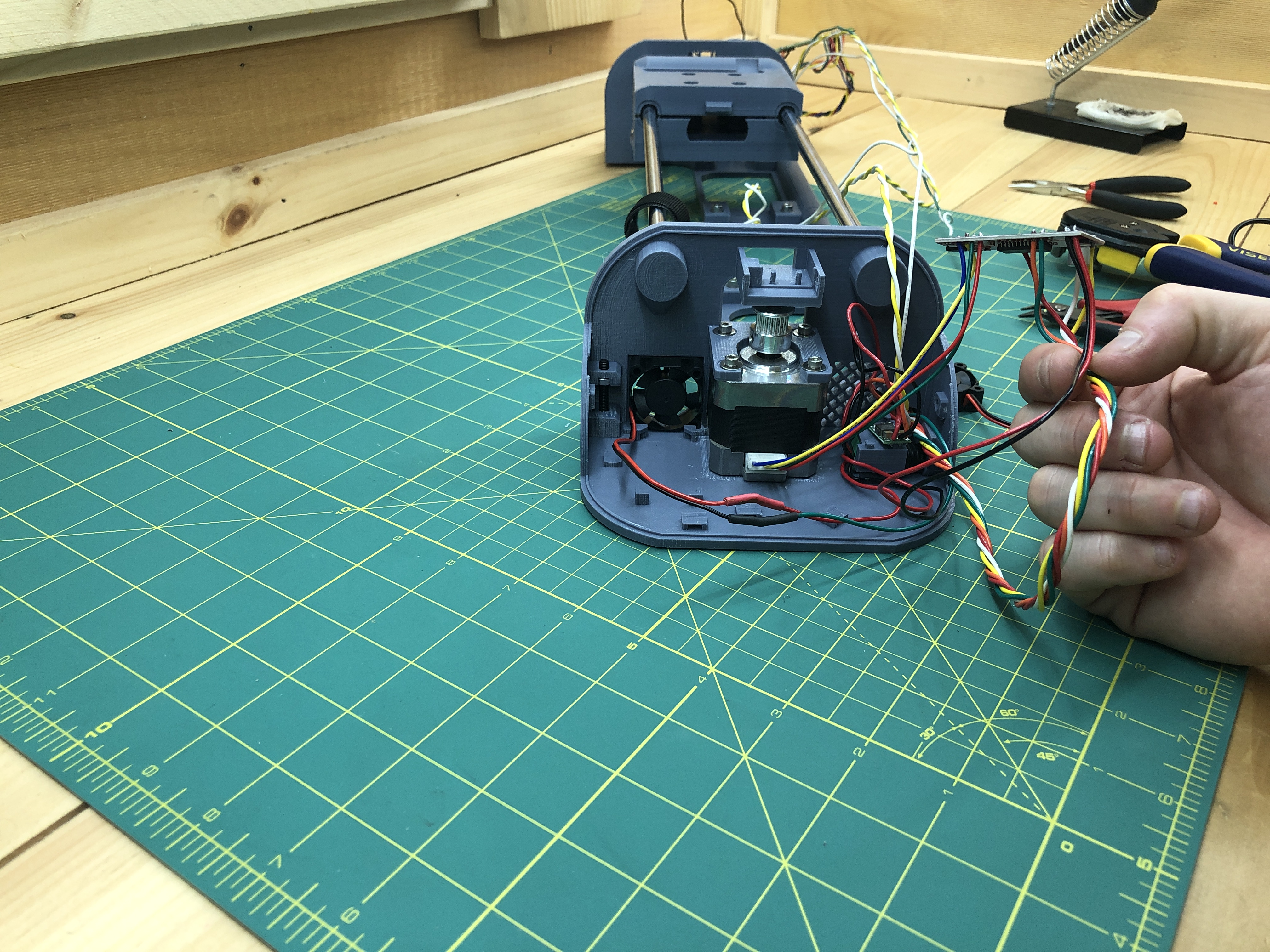
Grab 5 wires of different colors (except red and black). Cut them at 3 times the length of the distance between terminals when they are joined by their slabs (you can put them together loosely to see).
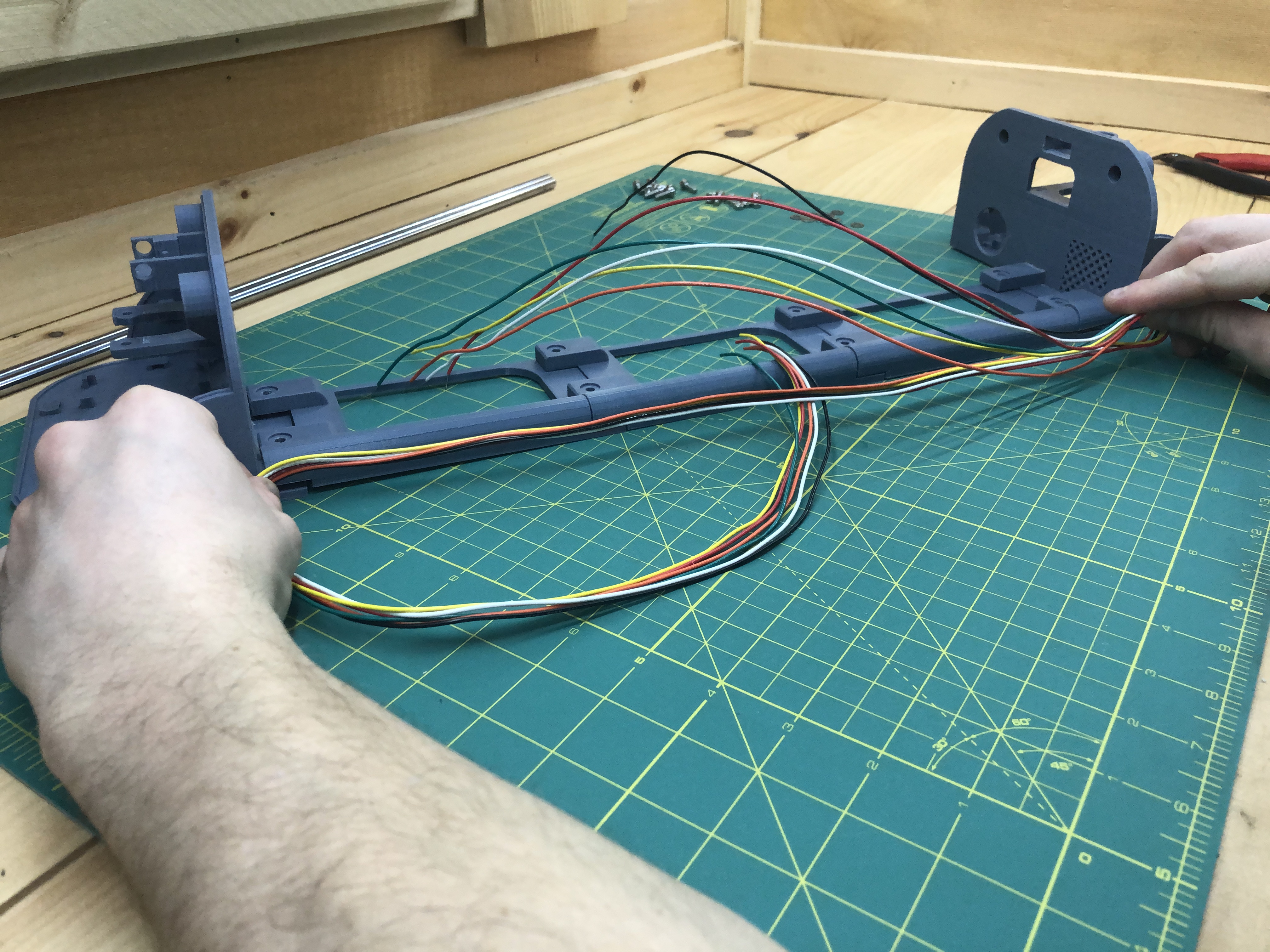
Now begins the very tedious task of twisting them lengthwise. It will help in multiple ways. First on each terminals, we’ll deal with bundles of wires known for a purpose. Second, it’ll be easier to feed them through the slabs. Lastly, I hear twisted wires help with electromagnetic interference, and well, I haven’t had any since I twisted my wires so I’ll say that’s true.
Then do another run with red, black and orange.
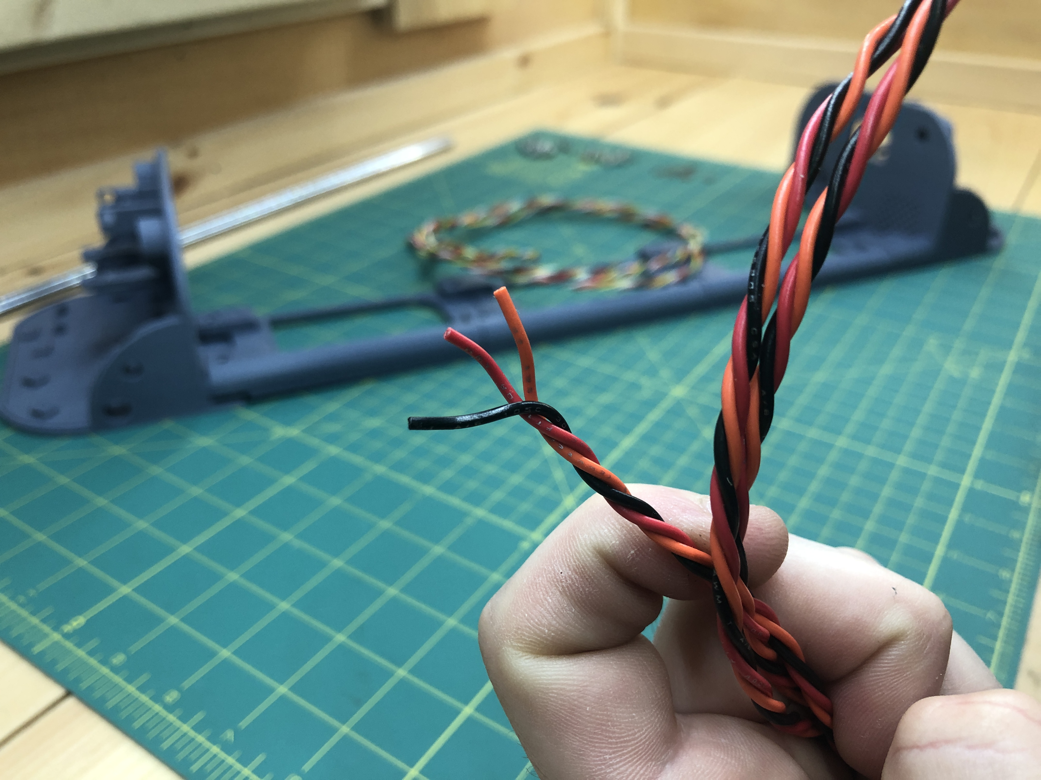
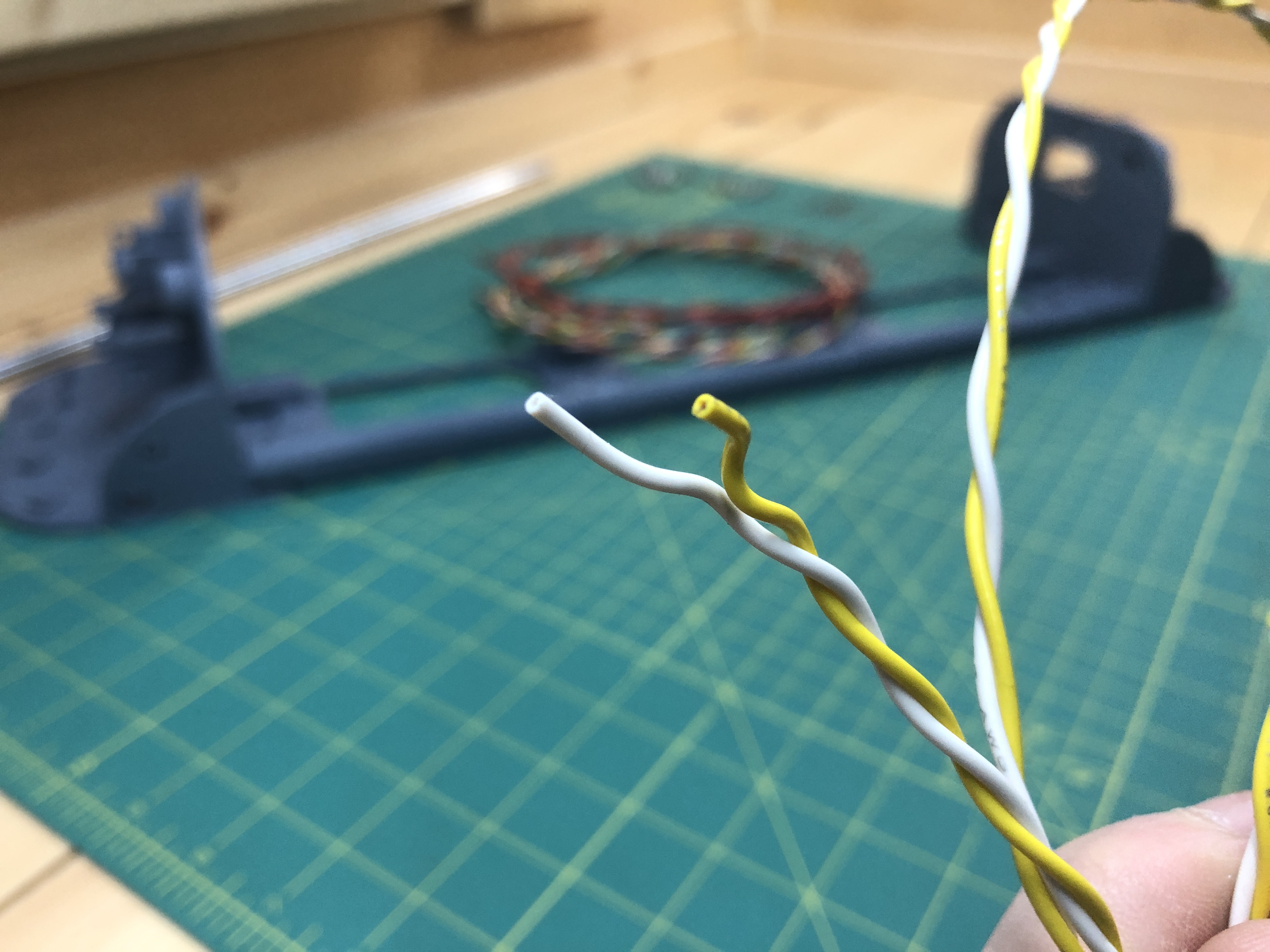
Then another with white and yellow.
Lastly, add a couple of wires of random colors to your spools, they don’t need to be twisted.
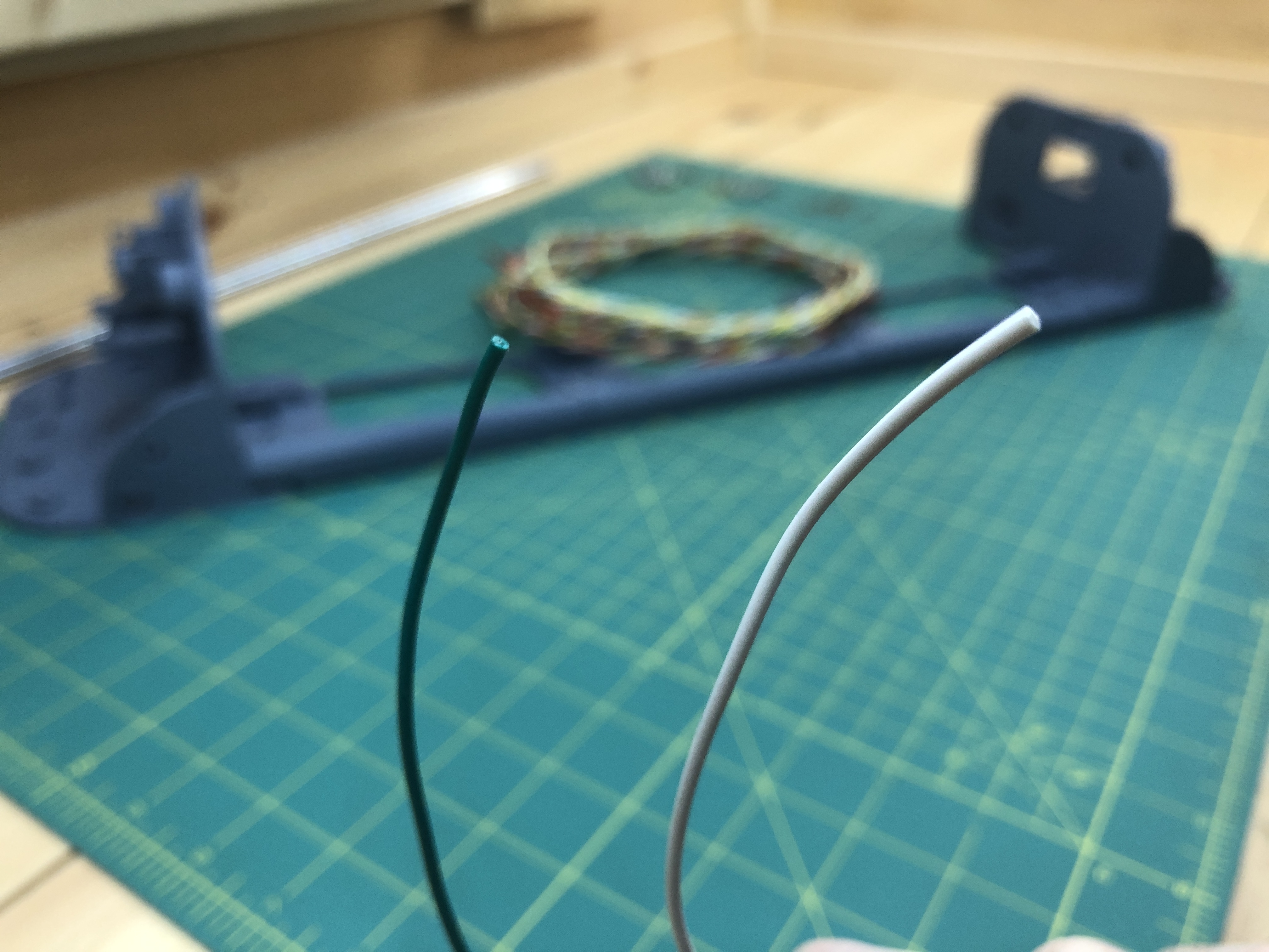
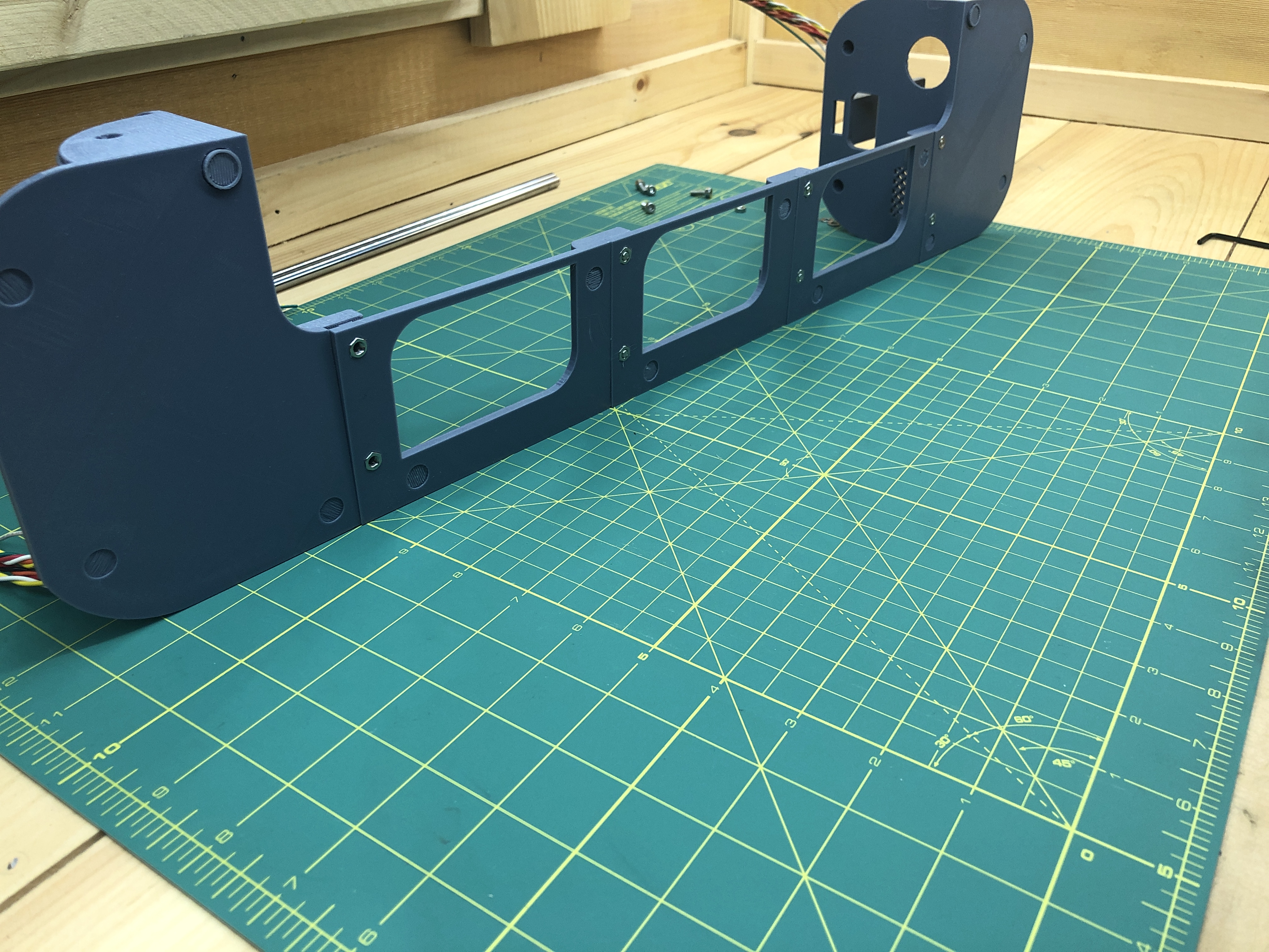
You should have the following bundles when you’re done.
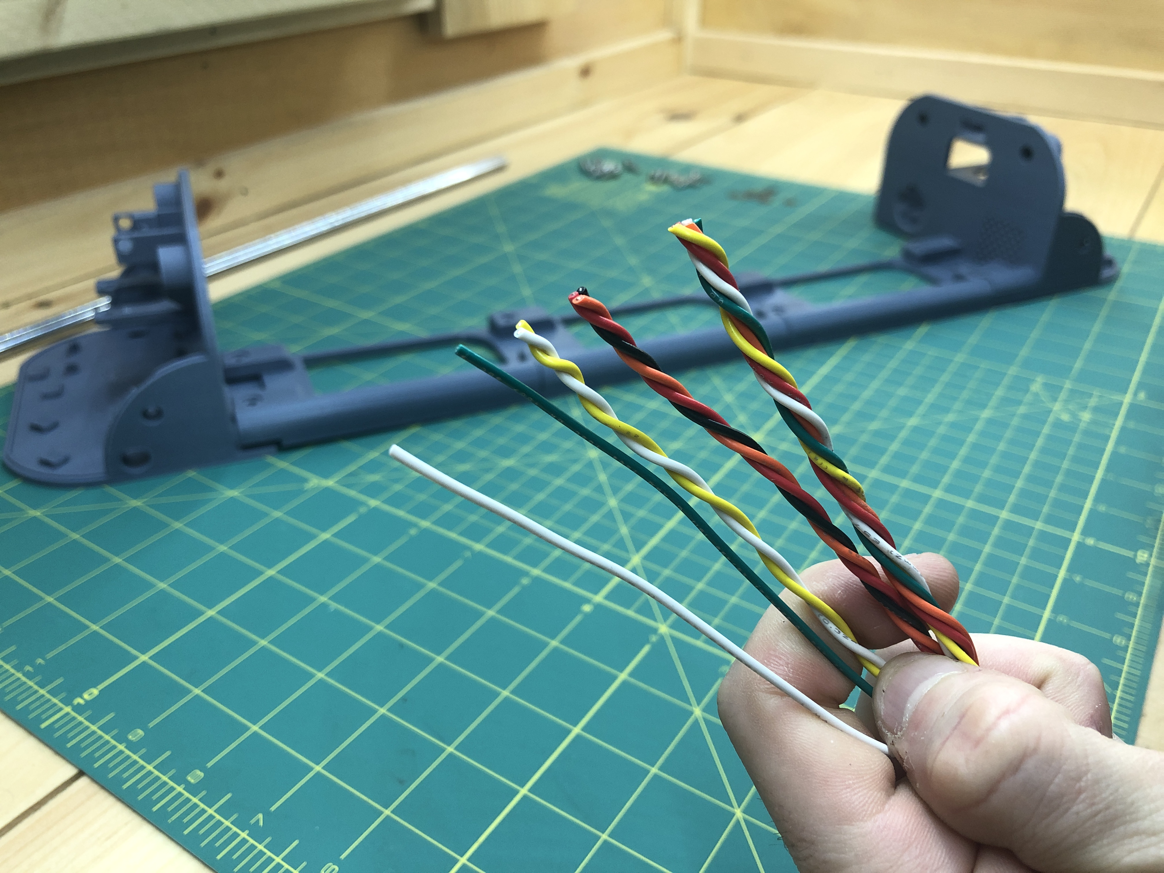
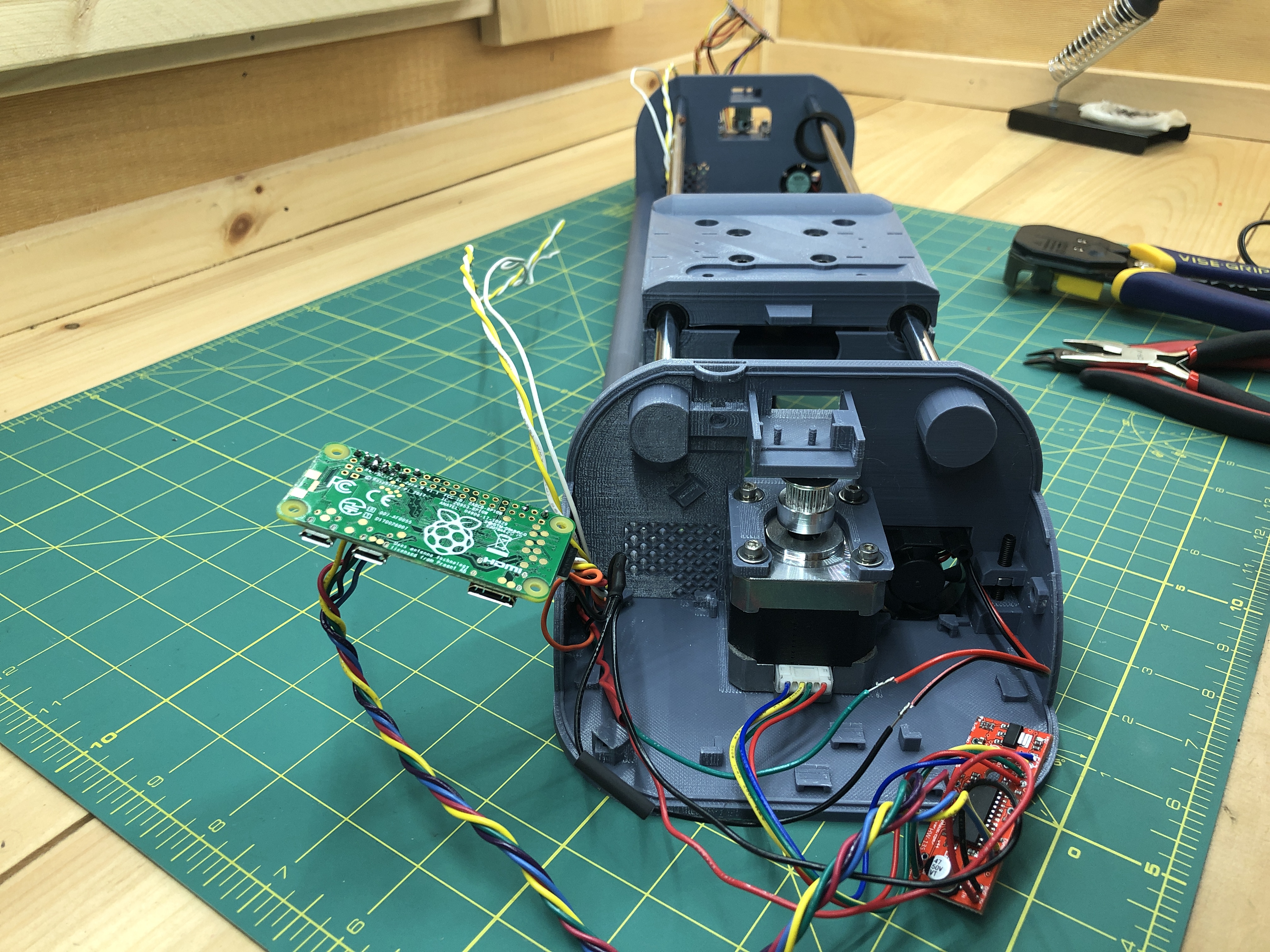
Grab them all and insert them into the bottom terminals corner, where an arch shaped hole is.
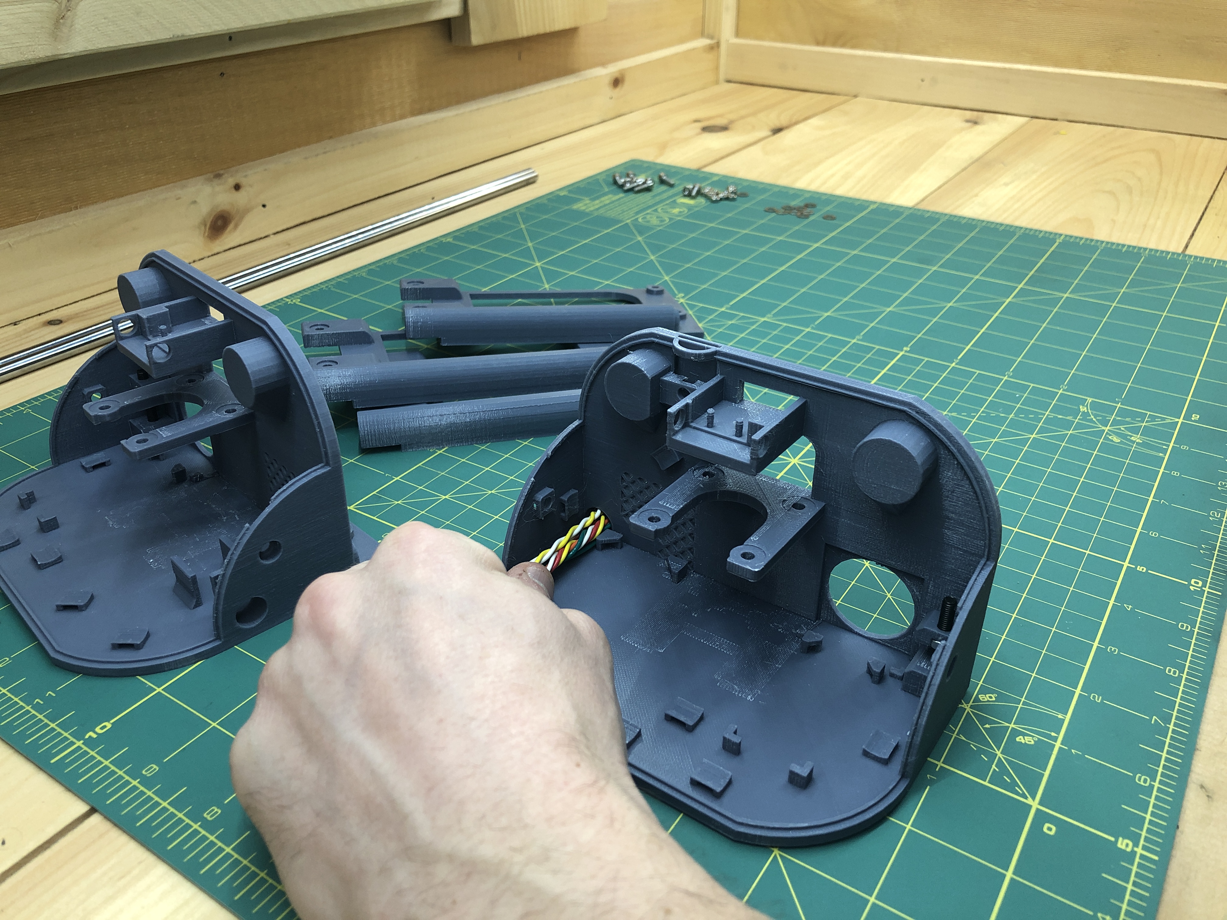
They’ll come out the other side (bottom view).
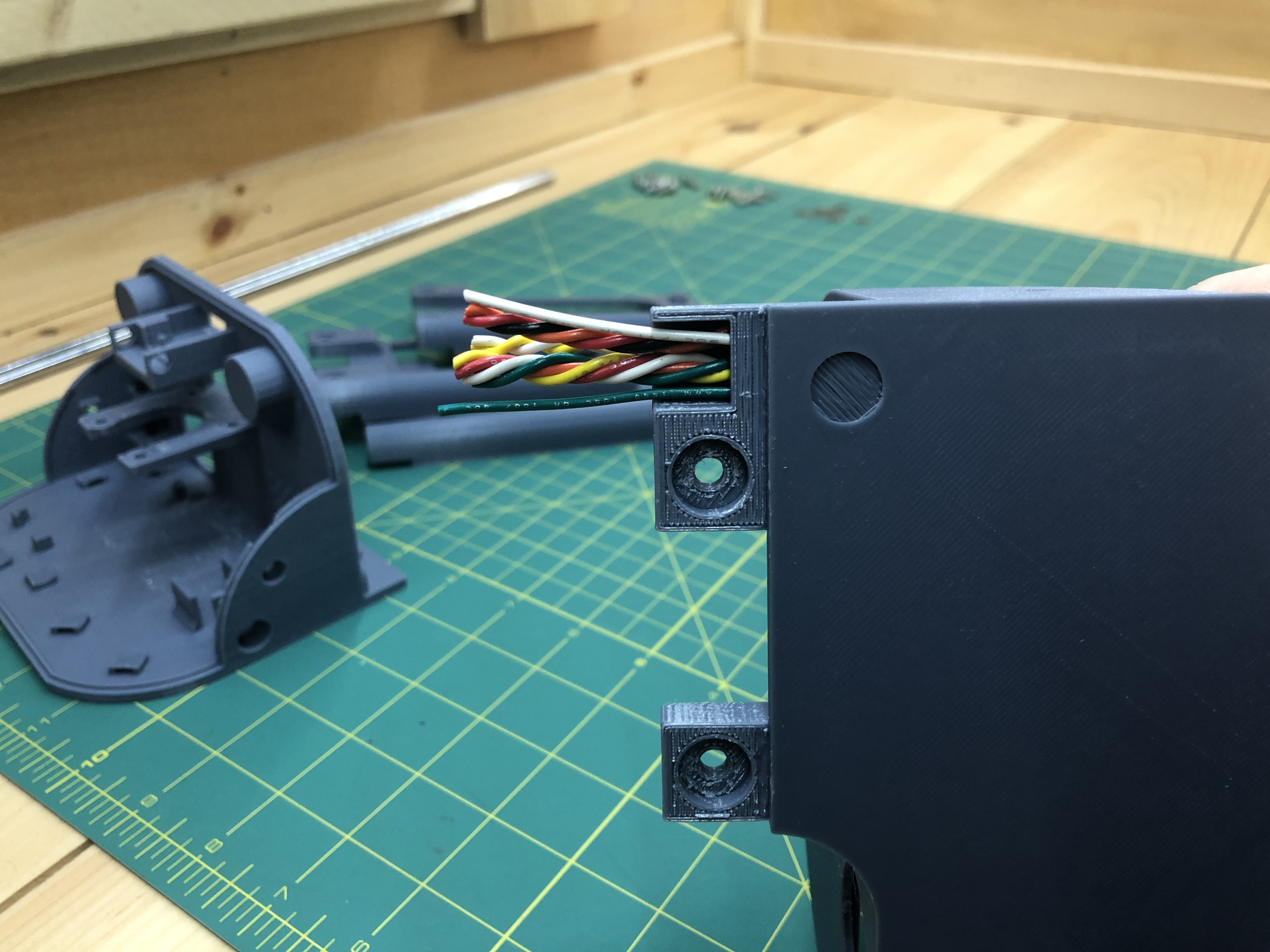
Insert them into the similarly shaped arch hole of a slab.
Until them come out the other side.
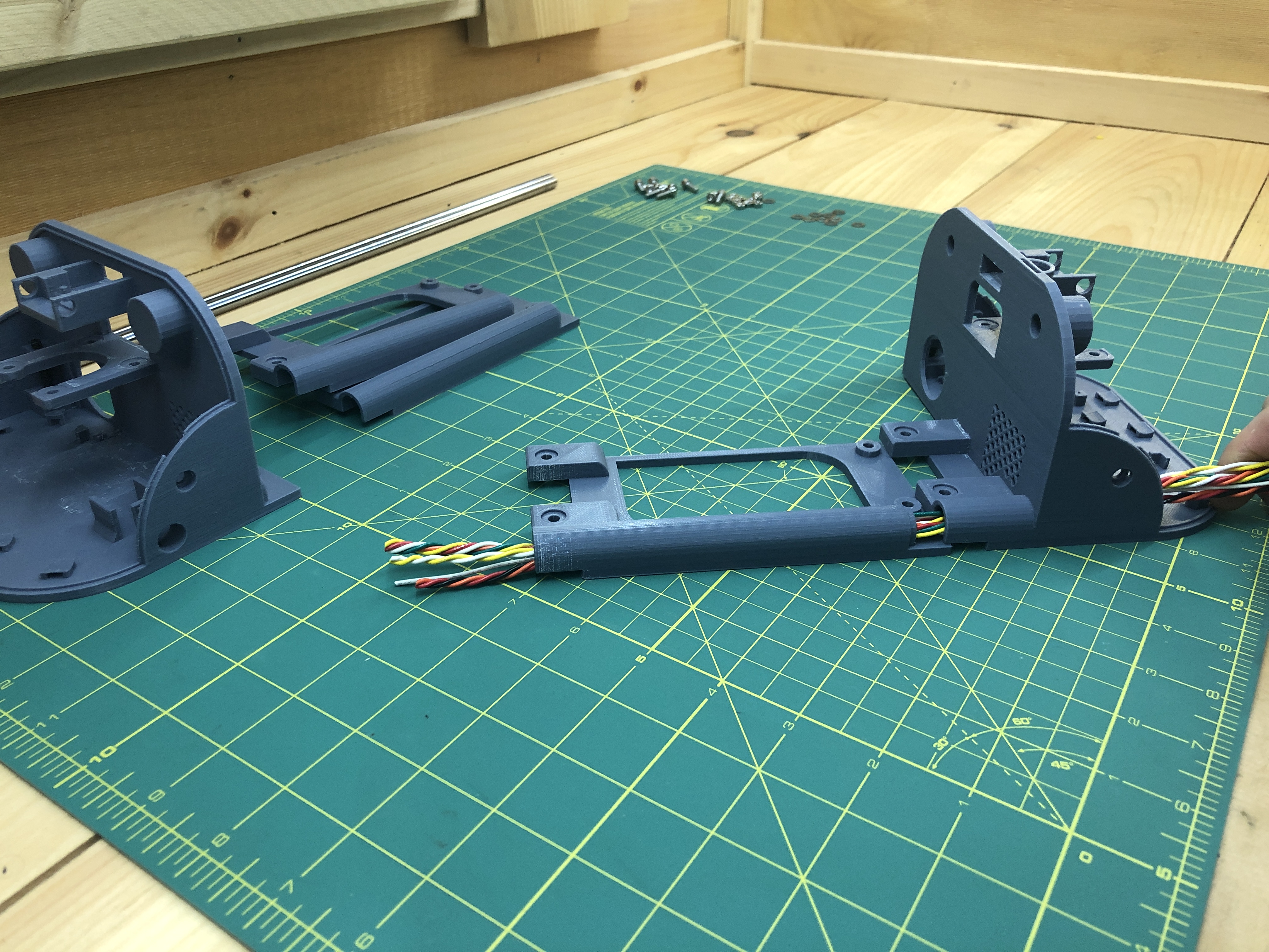
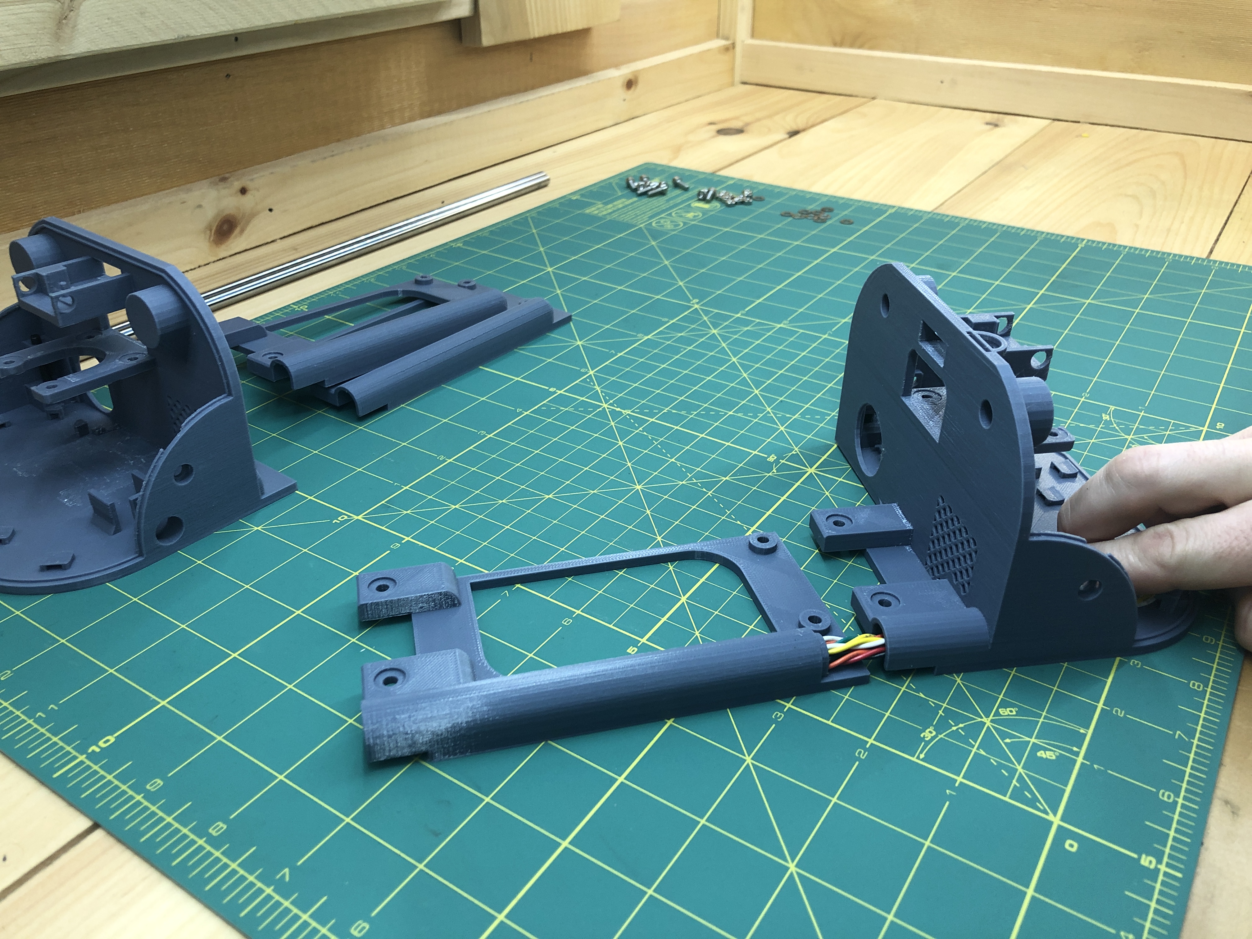
Repeat with the next 2 slabs.
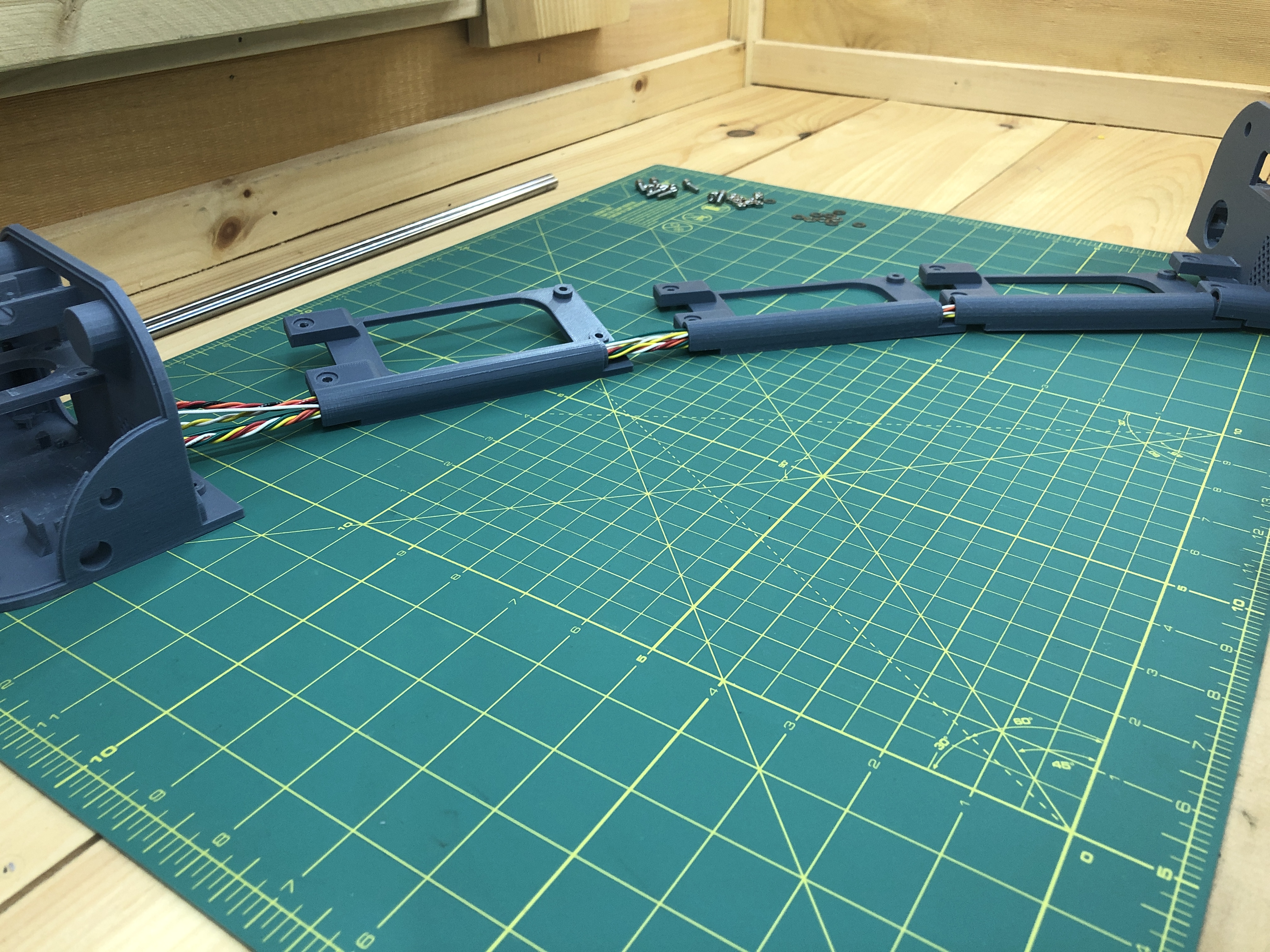
And in through the top terminal.
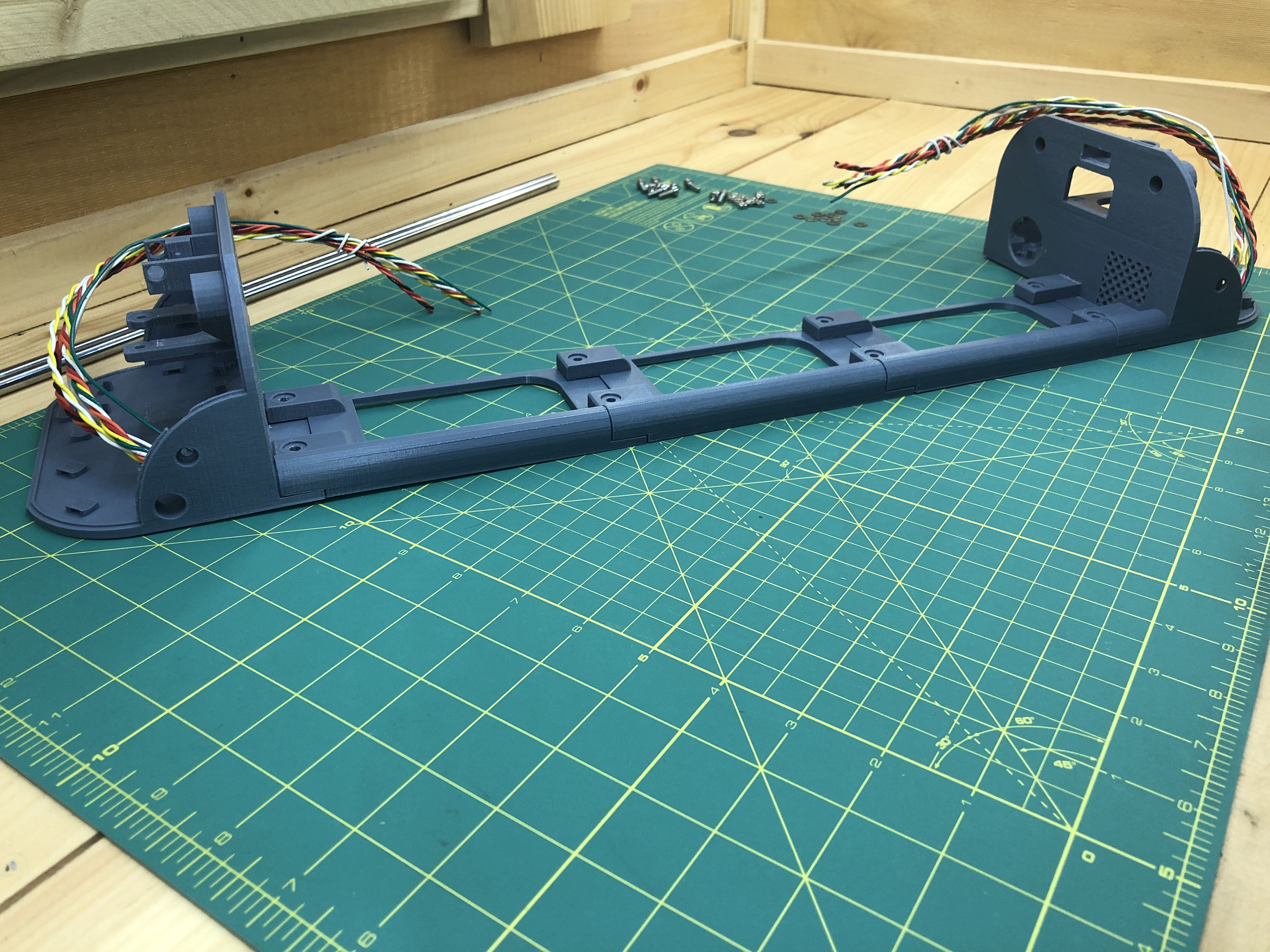
Insert M4 nuts into the bottom where receptacles exist (except for 2 where the top terminal joins).
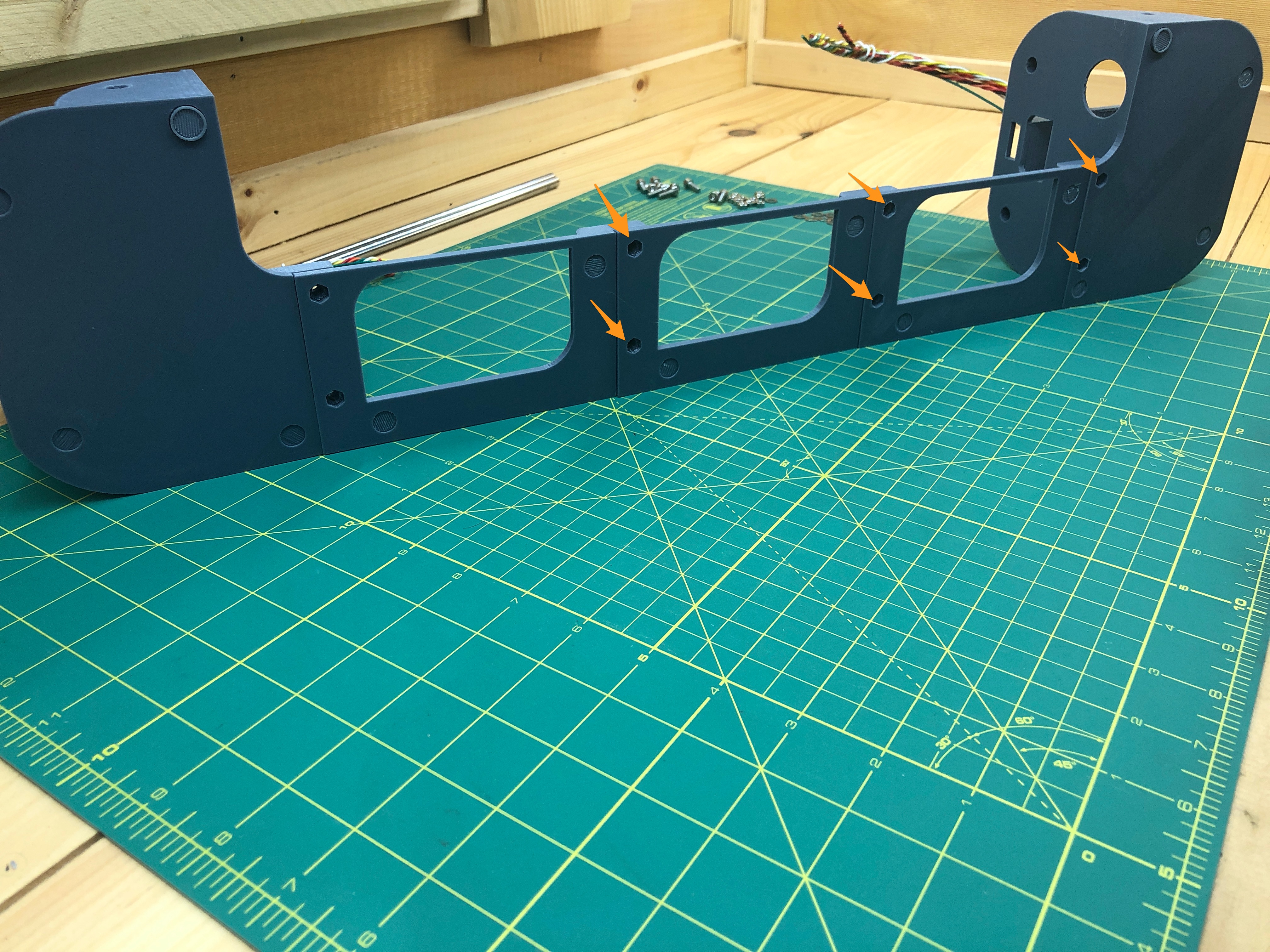
Screw in M4x12 hex screws from the top.
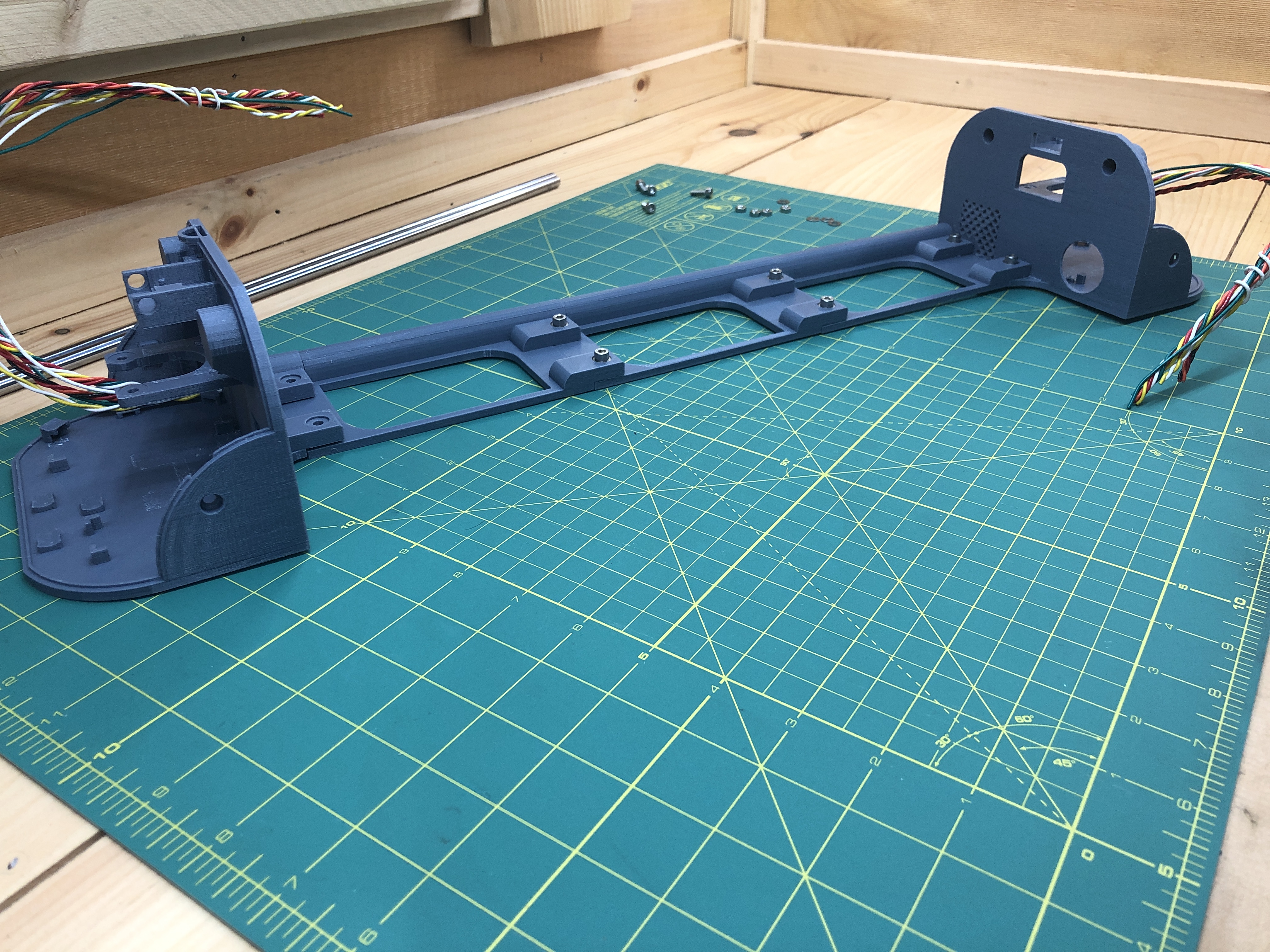
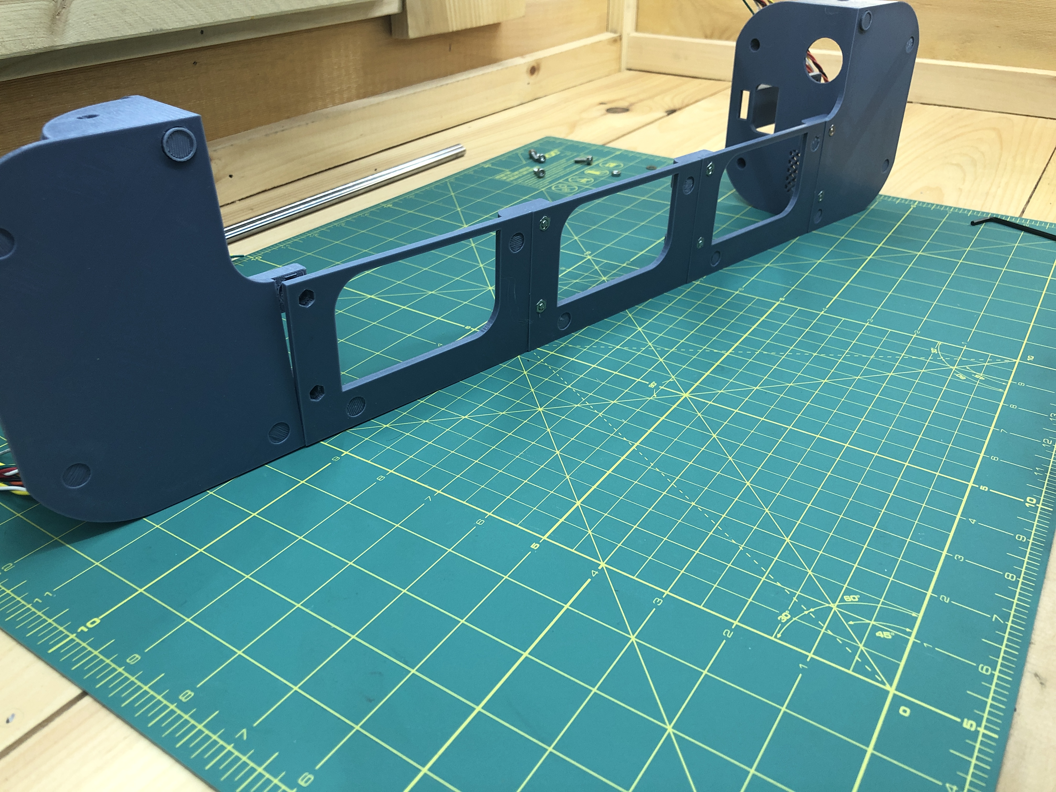
Put in nuts in receptacle for the last step (not screws yet).
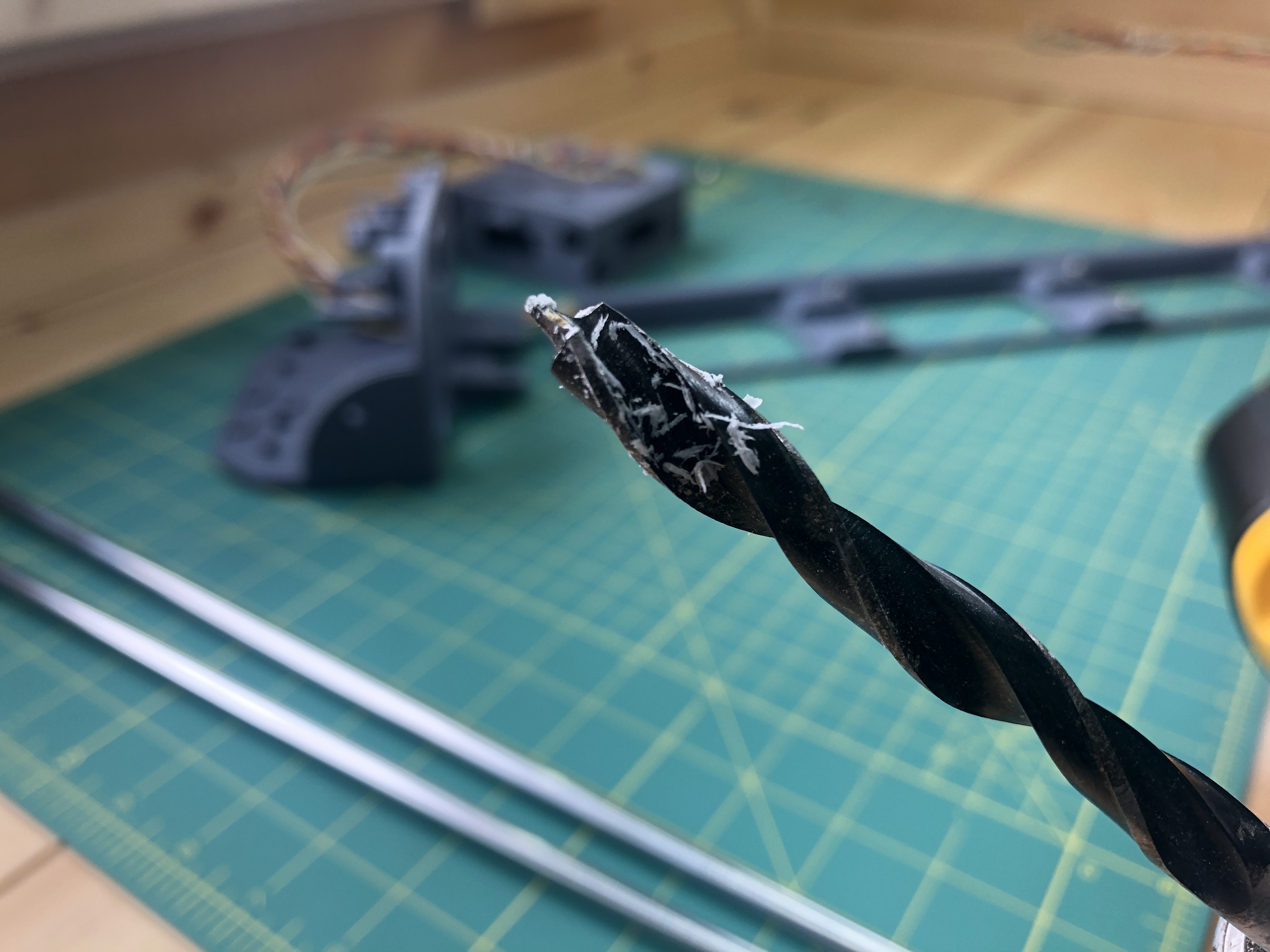
Grab your linear rods, and the gondola you build previously. Insert the rod in the bottom terminal.
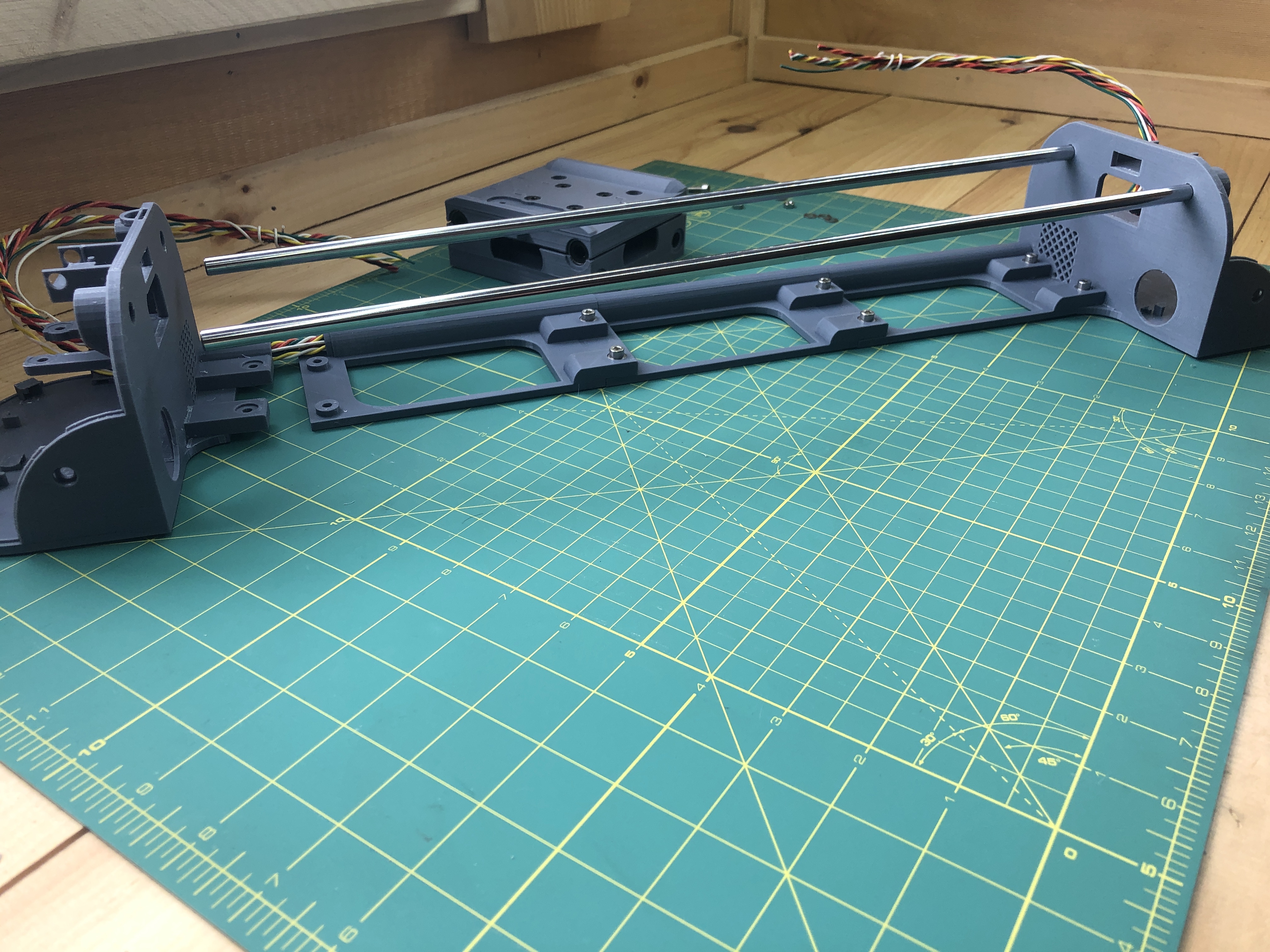
If the rods don’t fit, it’s ok, 3D printers tolerances can vary. Grab a drill with a bit 8mm or smaller and very, very, very carefully make the room you need for the rod. You do not want the rods to float in their hole, it will make drawings inaccurate, they are to be firmly held. Again, do not overdrill, take your time to remove a little bit of material at a time as you try the rod.
This is all I needed to remove to get mine to fit.
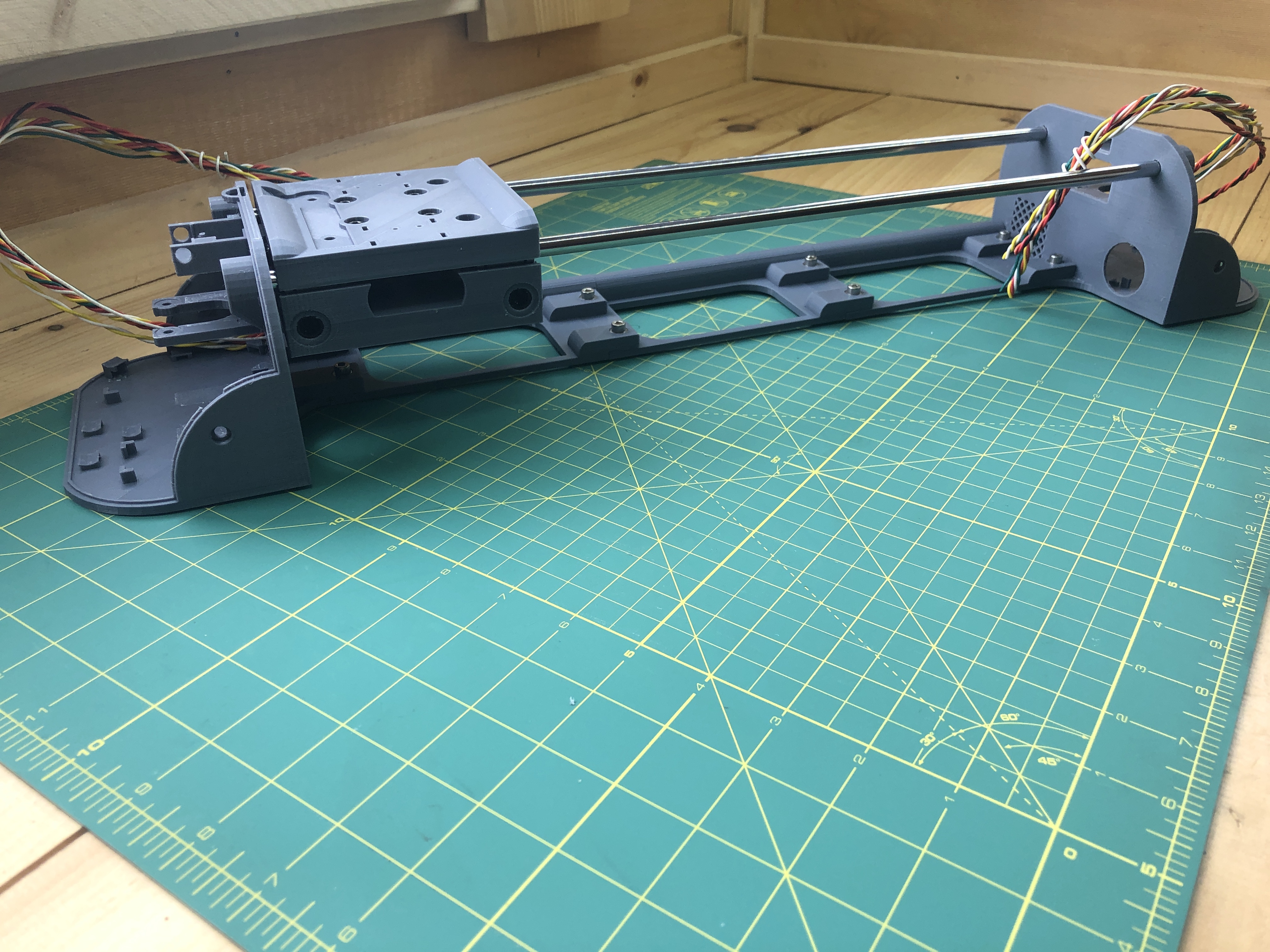
With both rods into the bottom terminal, slide the gondola on. Watch for the orientation. Insert the rods into the top terminal while rejoining it to the slabs.
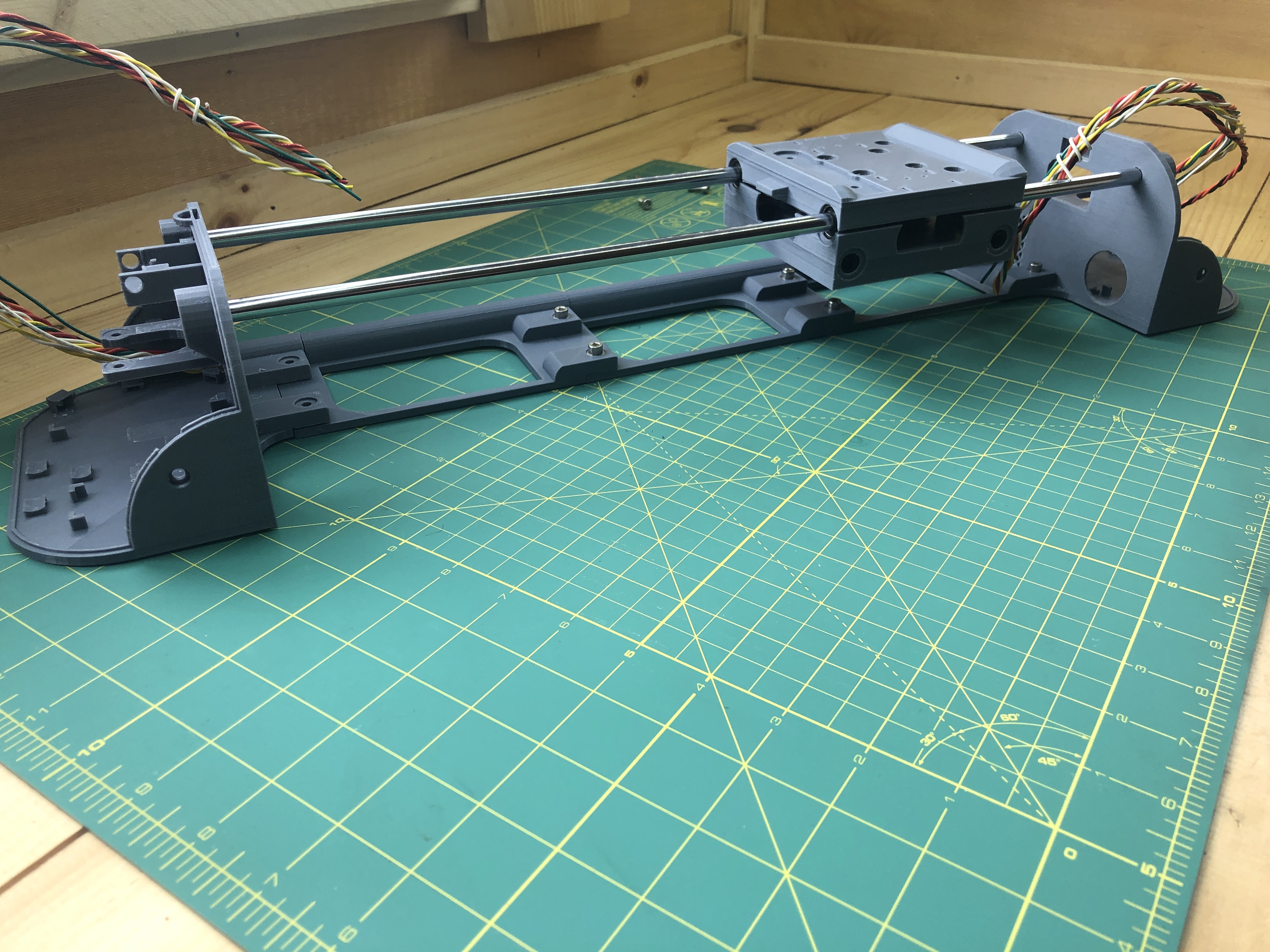
Put in the last M4x12 screws to commit the top terminal. Make sure the gondola slides smoothly.
4. Stepper Motors
Hardware:
8 M3x8 hex screws
8 washers
2 GT2 20T timing pulley
Electrical:
2 stepper motor
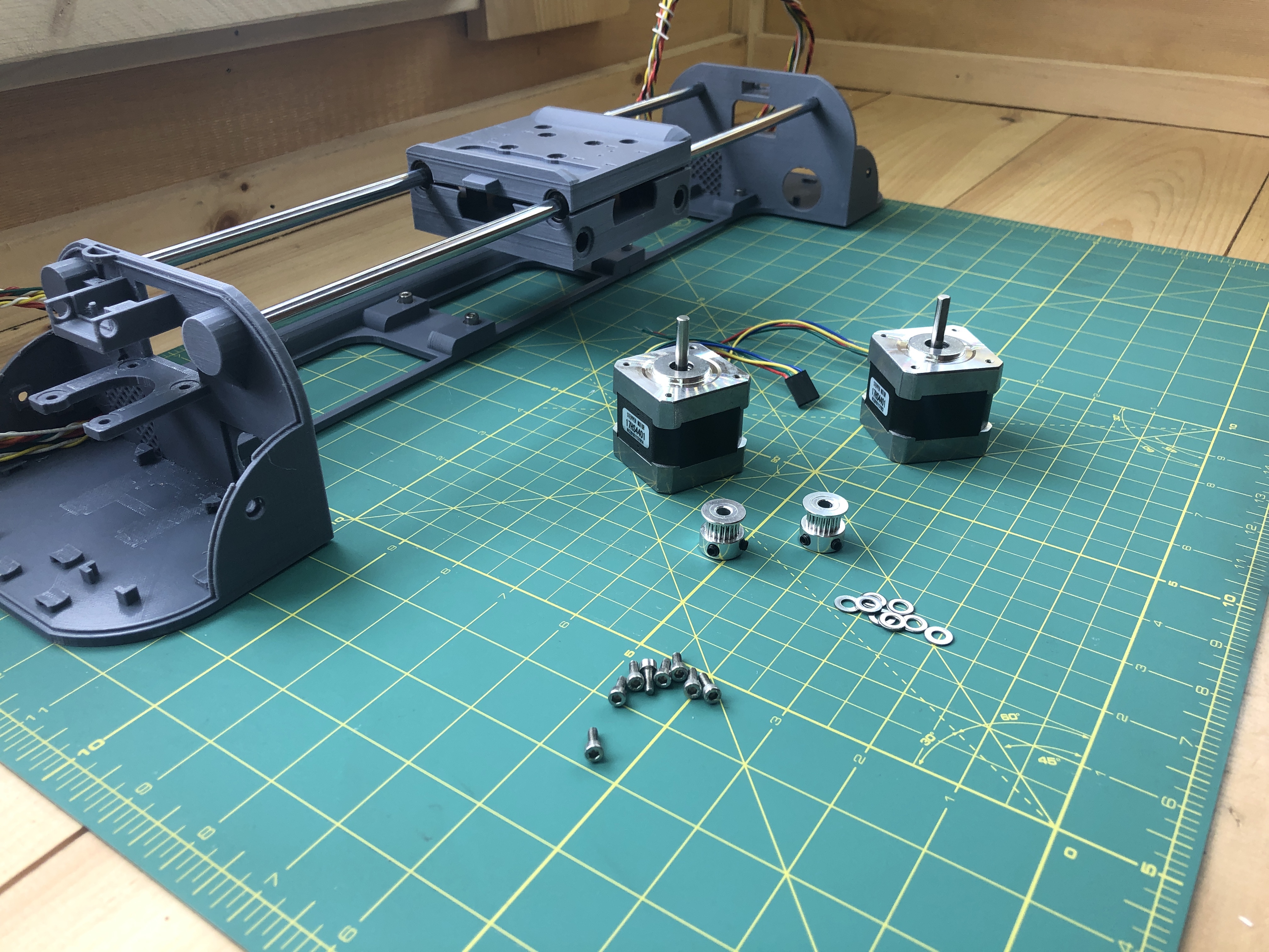
The pulleys had 2 embedded hex screws used to tighten them onto a stepper motor. Have one slightly out and one slightly in as such.
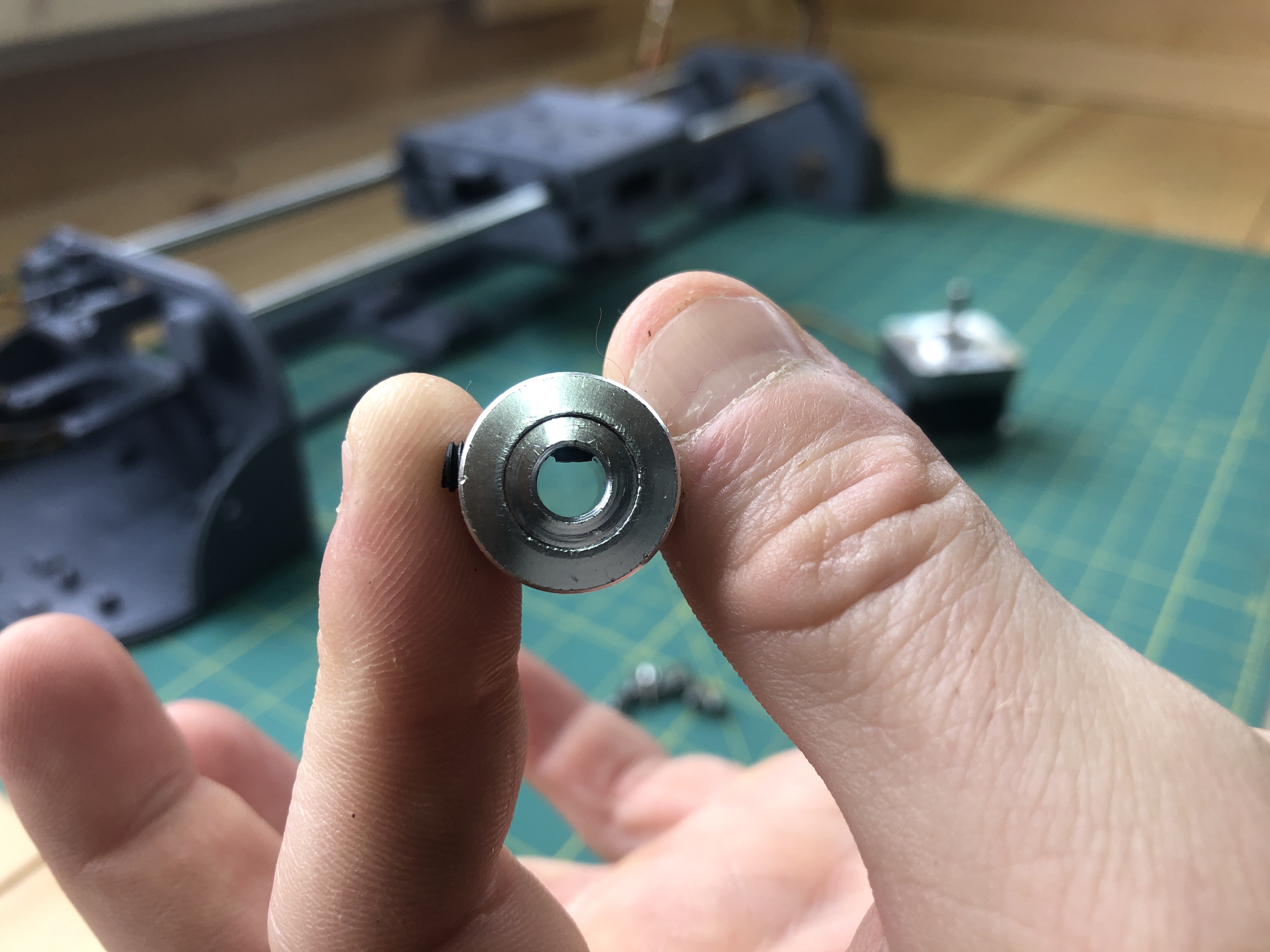
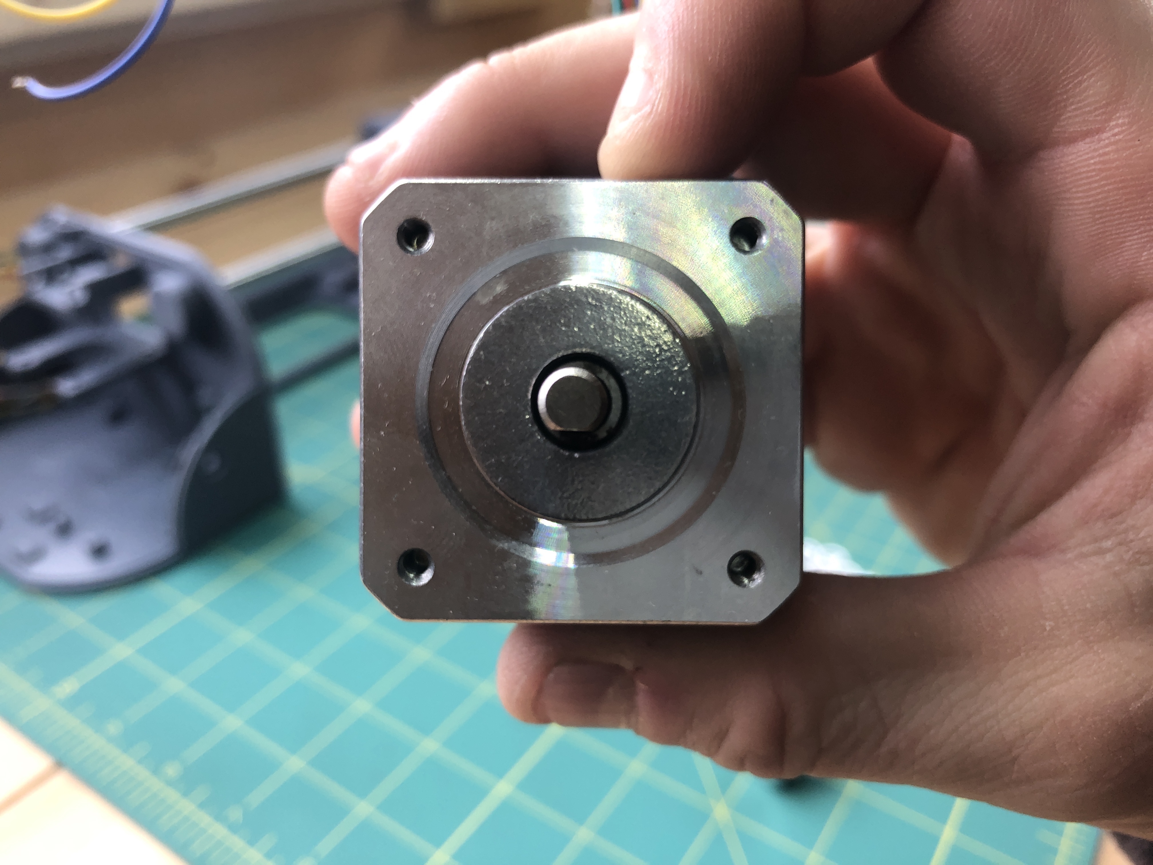
The stepper motors shafts have a flat side meant for the “slightly inside” pulley screw. This ensure that a pulley screw is tighten to the flat side which prevents slippage.
Slide the pulley on and tighten both screws. The pulley’s height wants to match that of the stepper motor’s shaft.
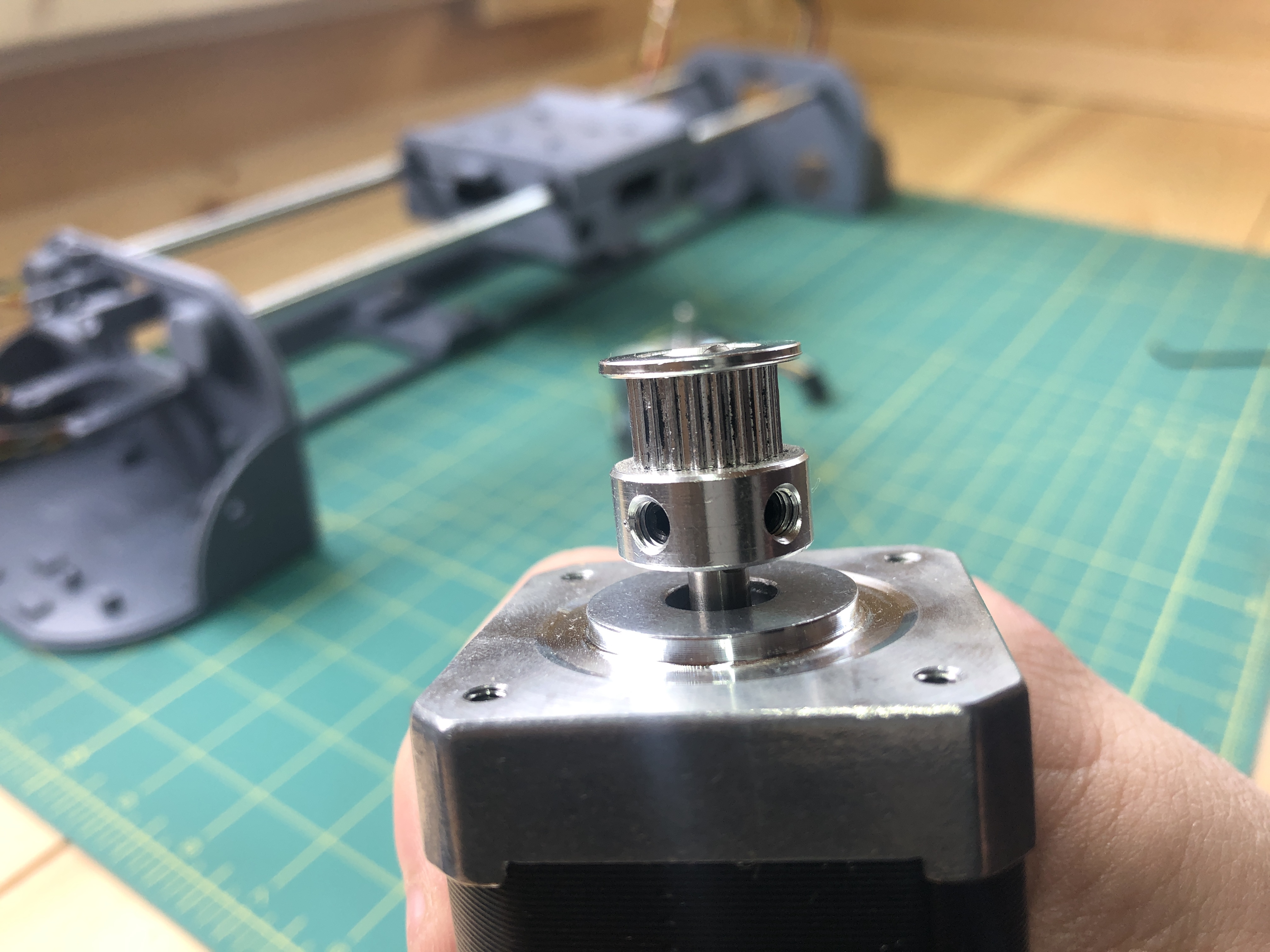
Do this for both motors.
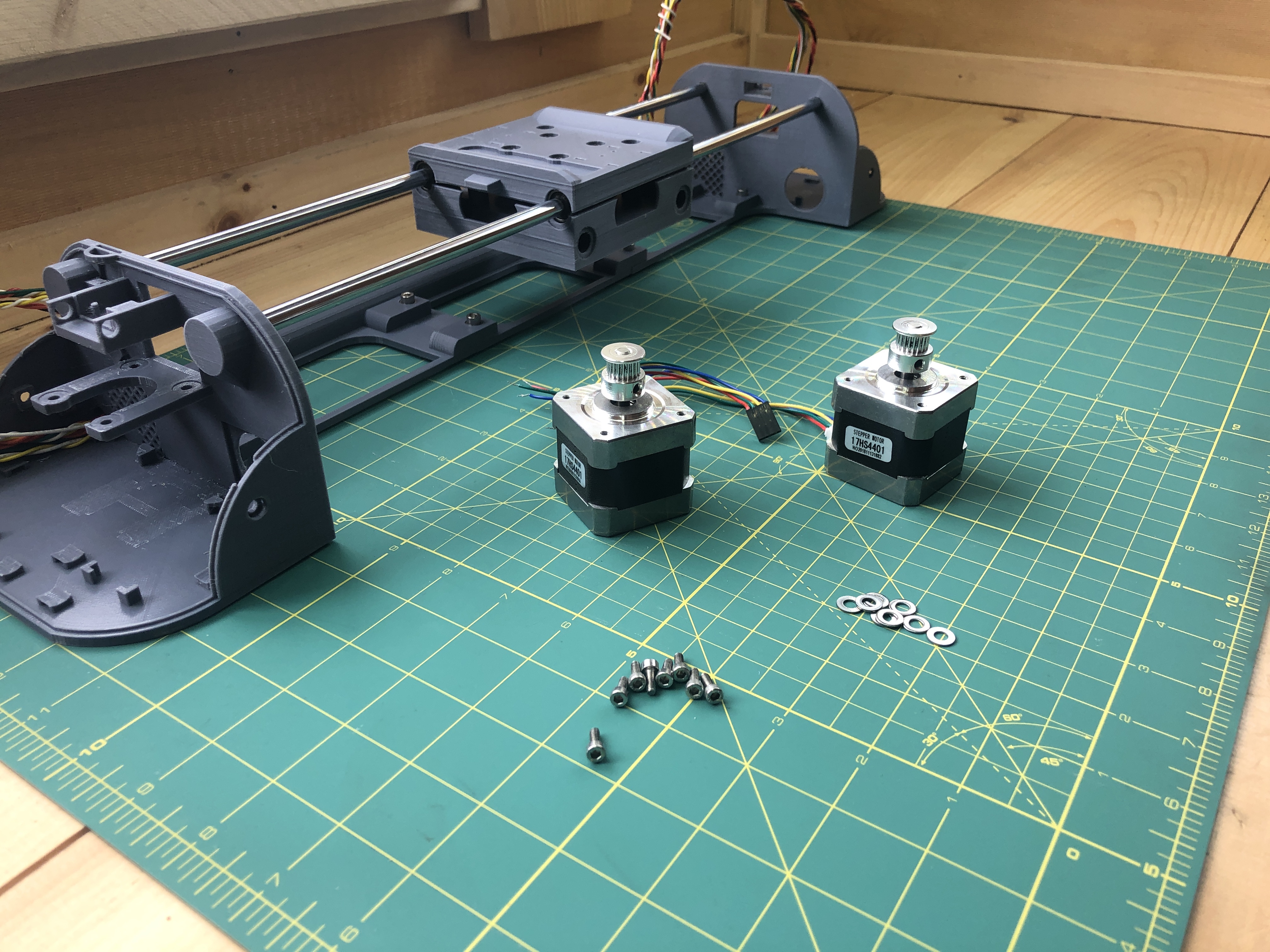
Insert a motor in a terminal.
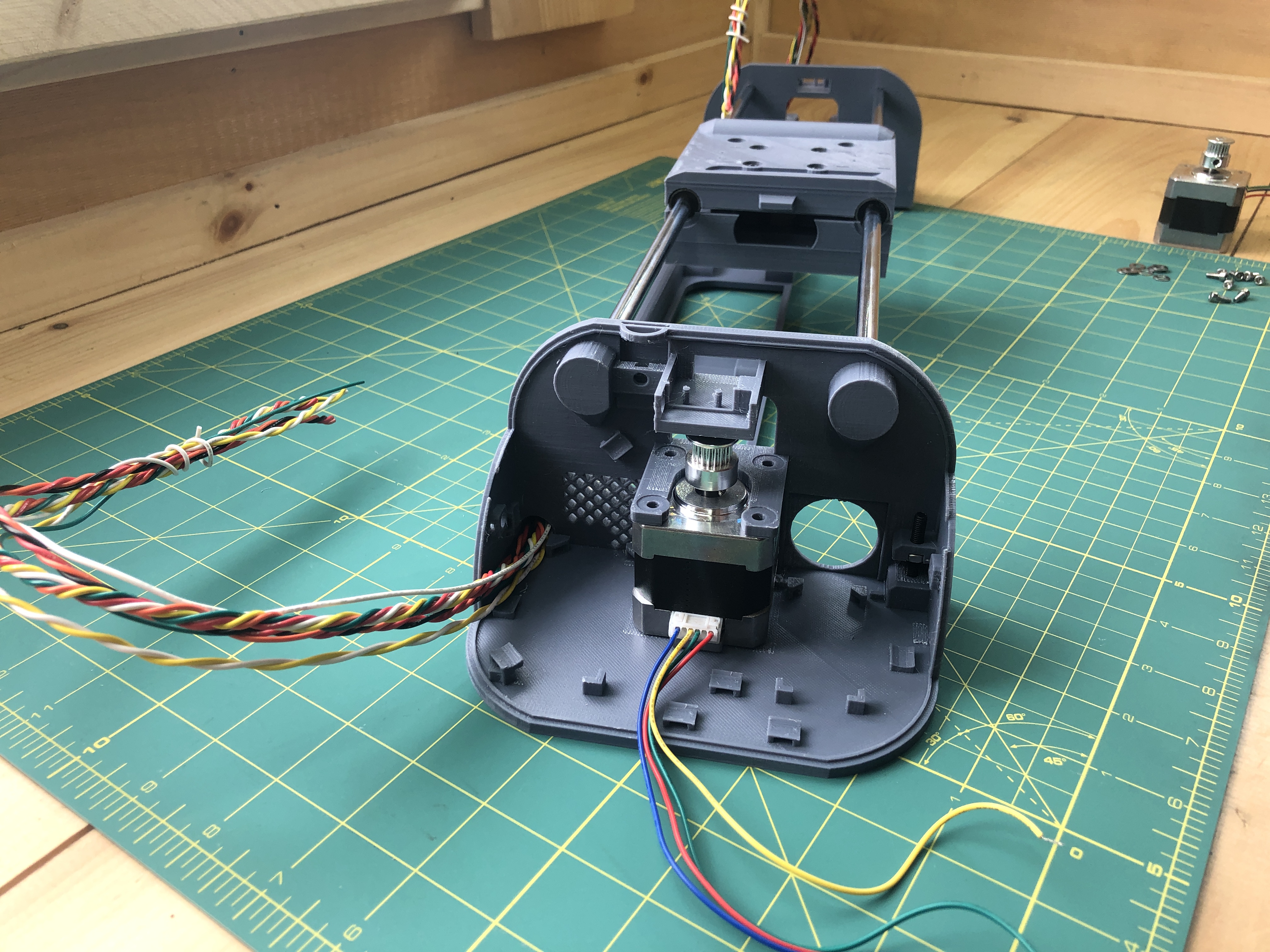
Then it’s washers and M3x8 screws, nothing too crazy :).
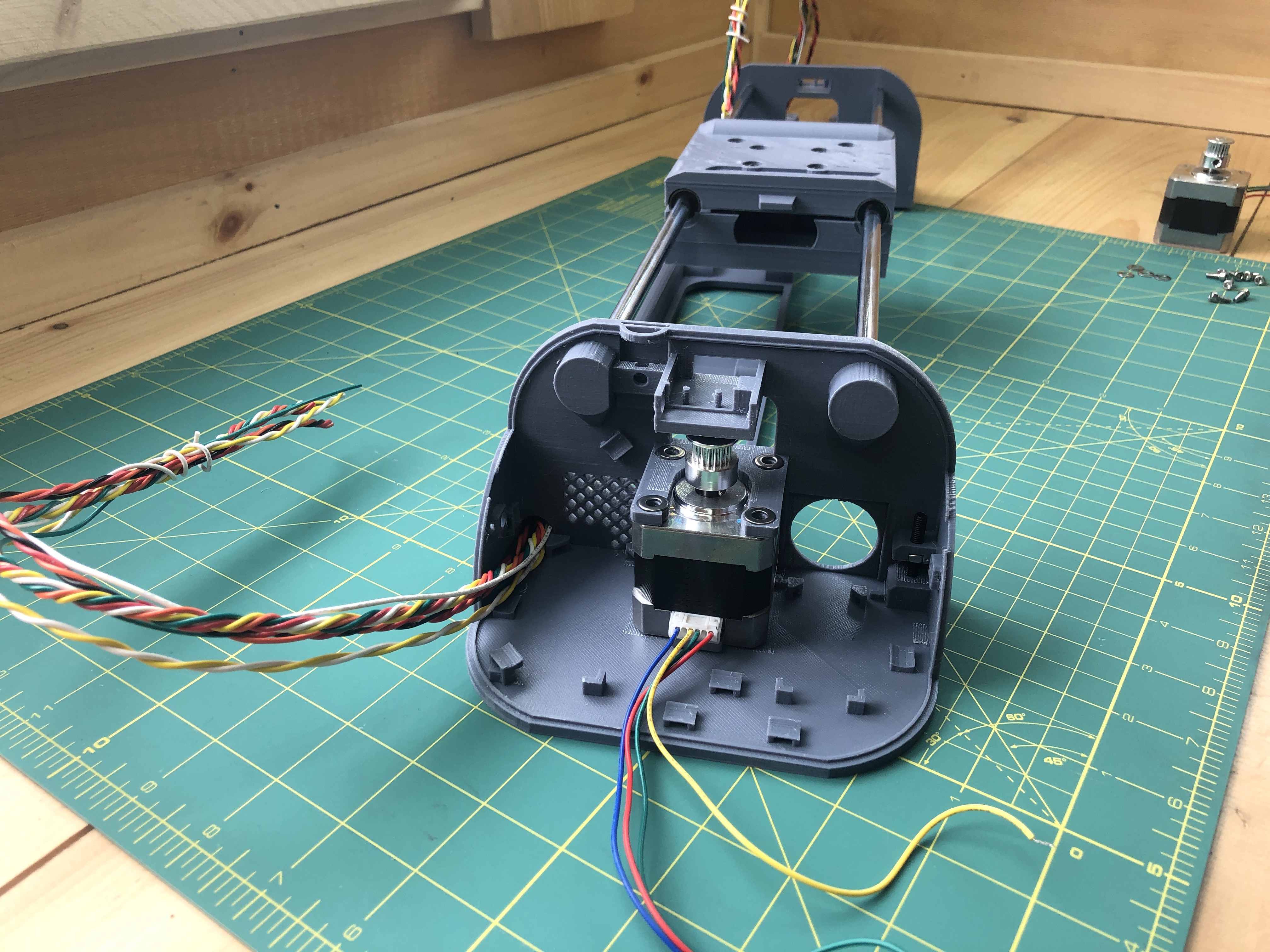
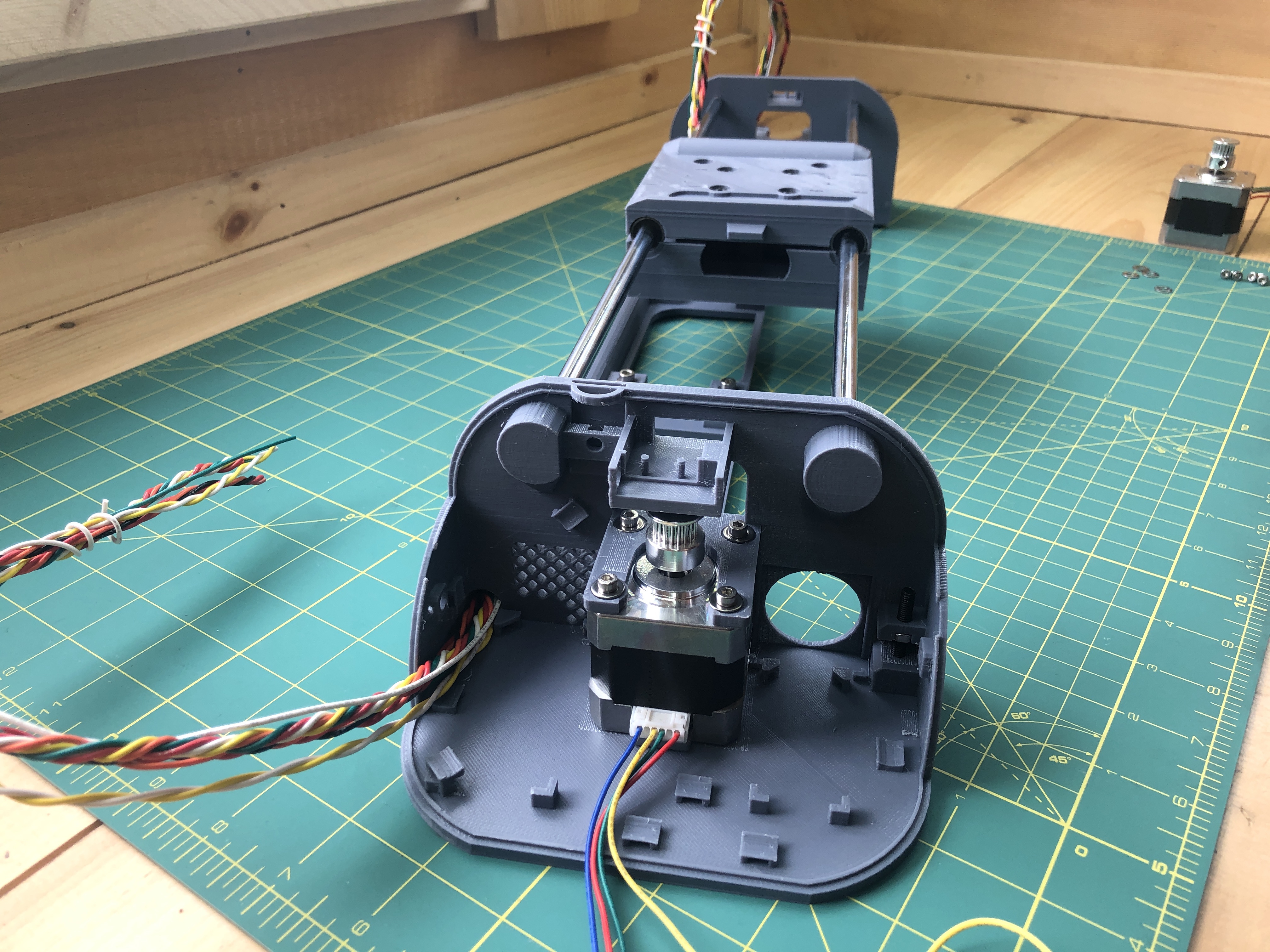
Do this for both terminals.
5. Power
3D parts:
terminal_top_power_supply_holder
Electrical:
voltage regulator
12V power supply female connector
wiring
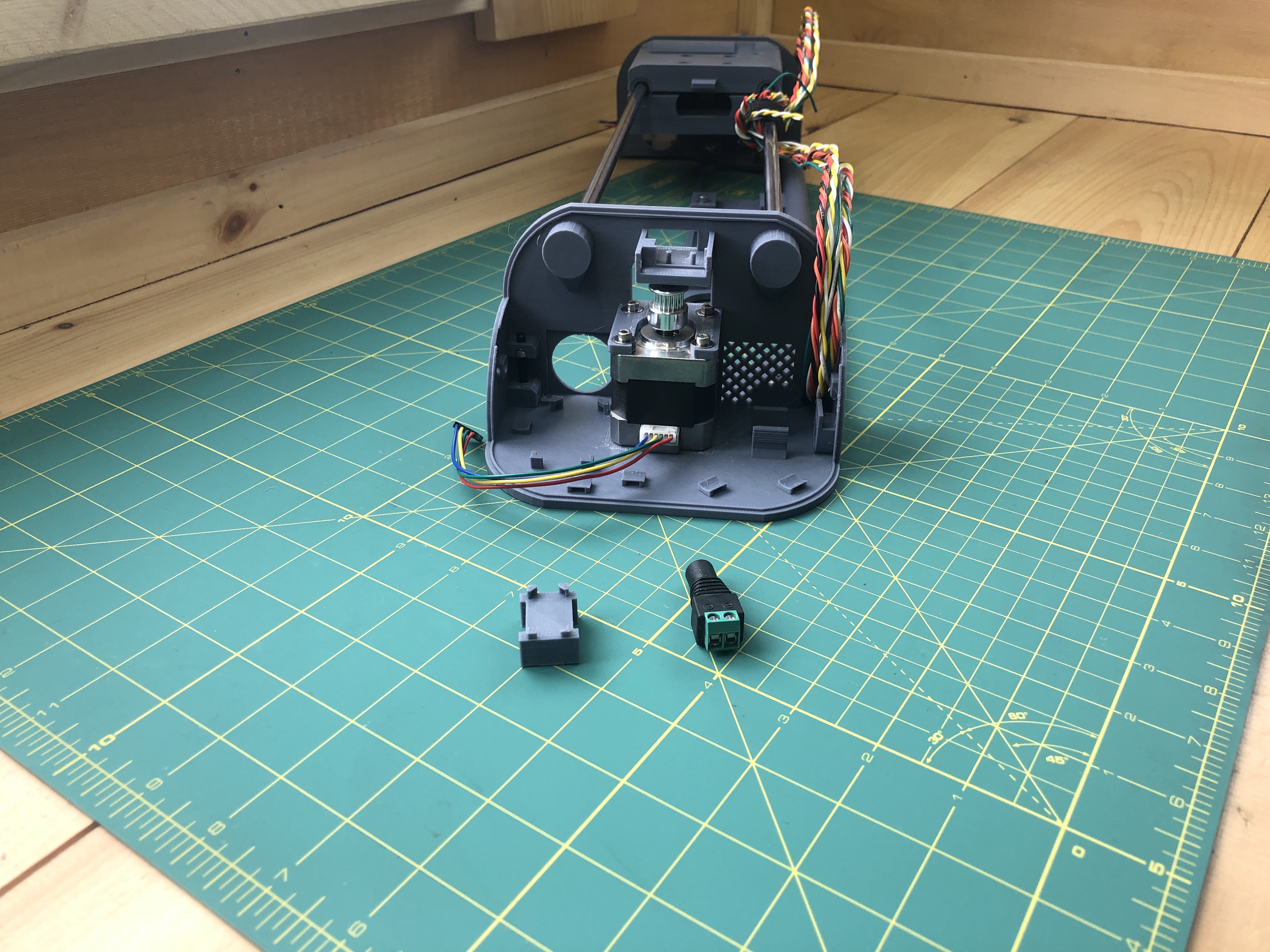
Insert the 12V power supply female connector into the top terminal. As always, fits may be tight and fabrication and 3D printing can vary, don’t hesitate to remove material where needs be.
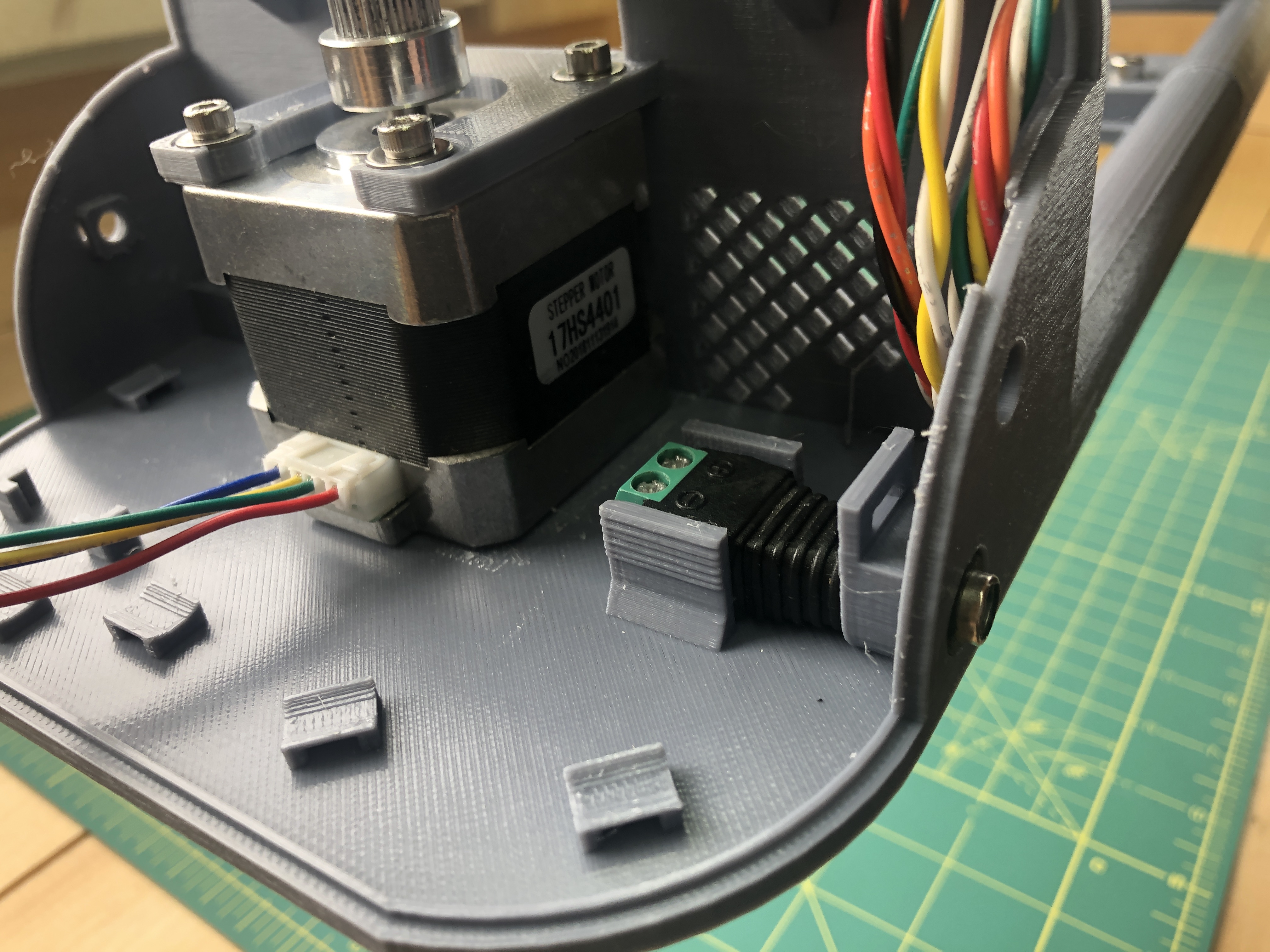
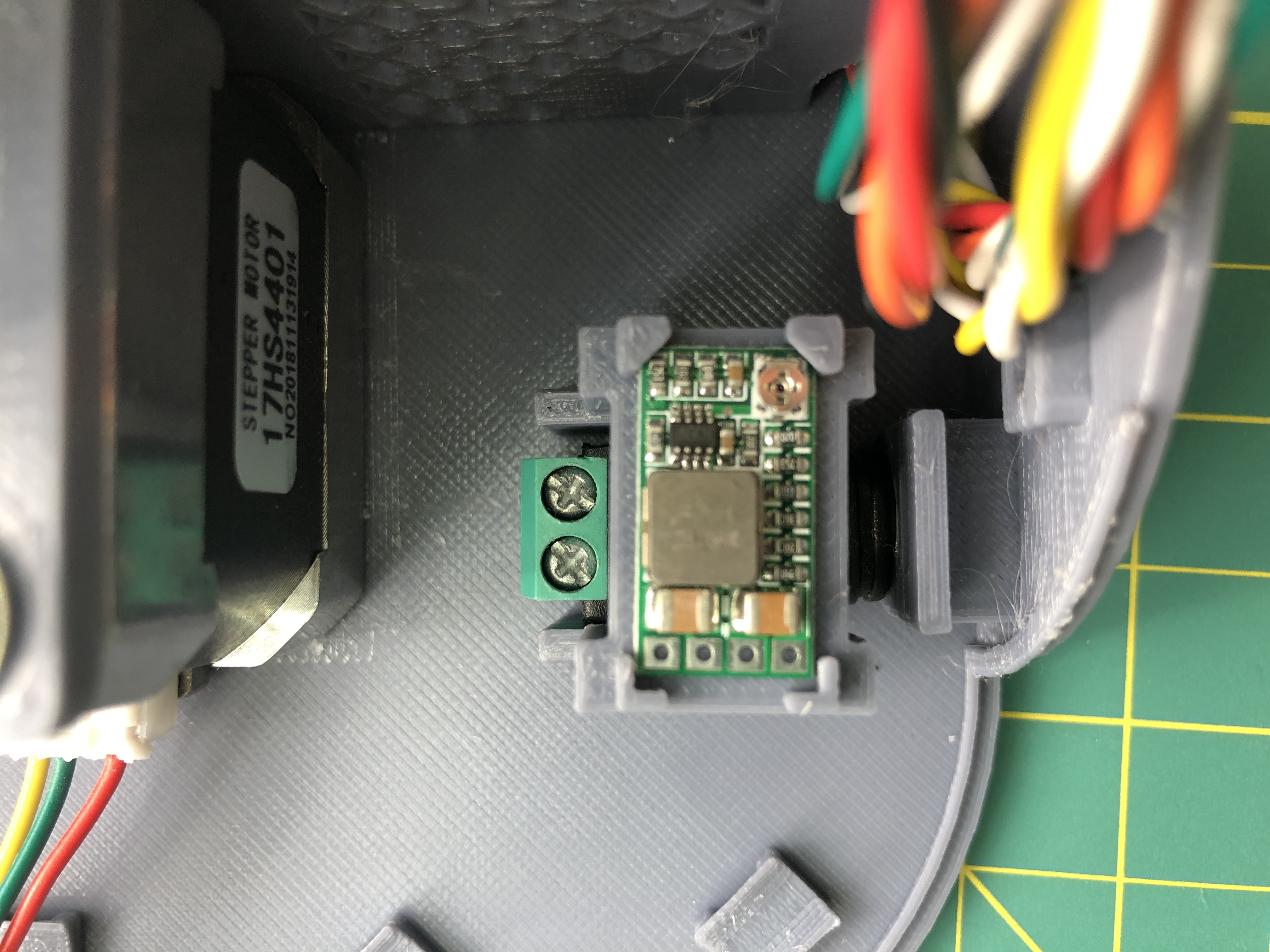
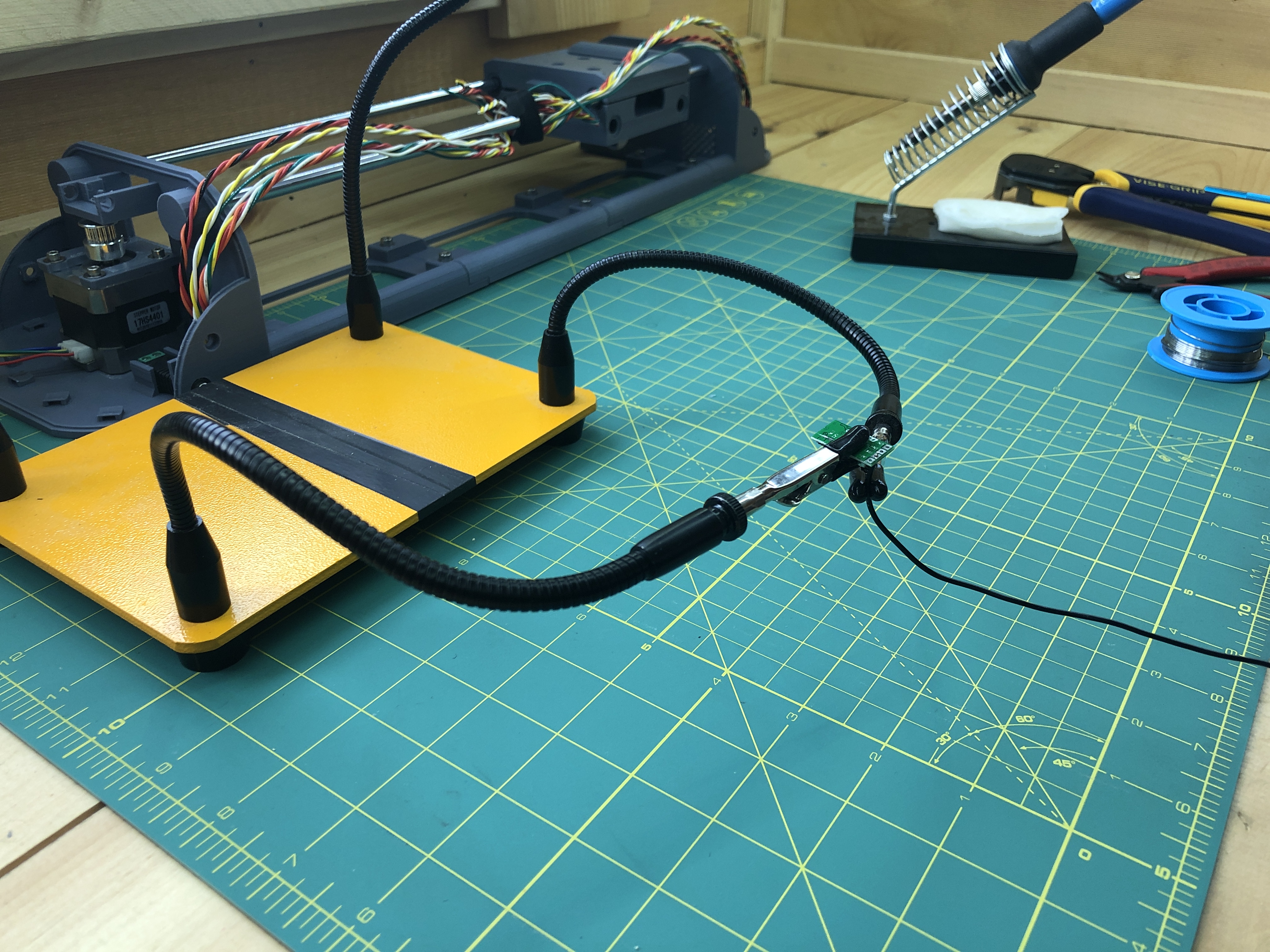
The voltage regulator will go on the terminal_top_power_supply_holder which crimps on, but don’t crimp it on yet. This is just to see where we’re going.
Before we proceed further, a connector interlude.
We’re about to wire electrical components. In this build I will solder them, instead you can use headers and dupont connectors which can be added and removed at will. Removable connectors are nice in that mistakes are easy to fix, and components easier to repurpose. This is what I did for several previous iterations of PlottyBot. The one I’m building now however is a final version and very much meant to plot through the ages. I want sturdy connections unaffected by plotting vibration and transport. I have plotted for hundreds of hours on dupont connectors, they are fine but will come loose on occasion. Nothing that can’t be wiggled back in place.
Choose your path, headers or connectors or soldering.
The following dupont connector set is available from Amazon. If you go this route, I recommend you try a few wires to practice on before you move on to your plotter. There’s definitely a technique to it.
</interlude>
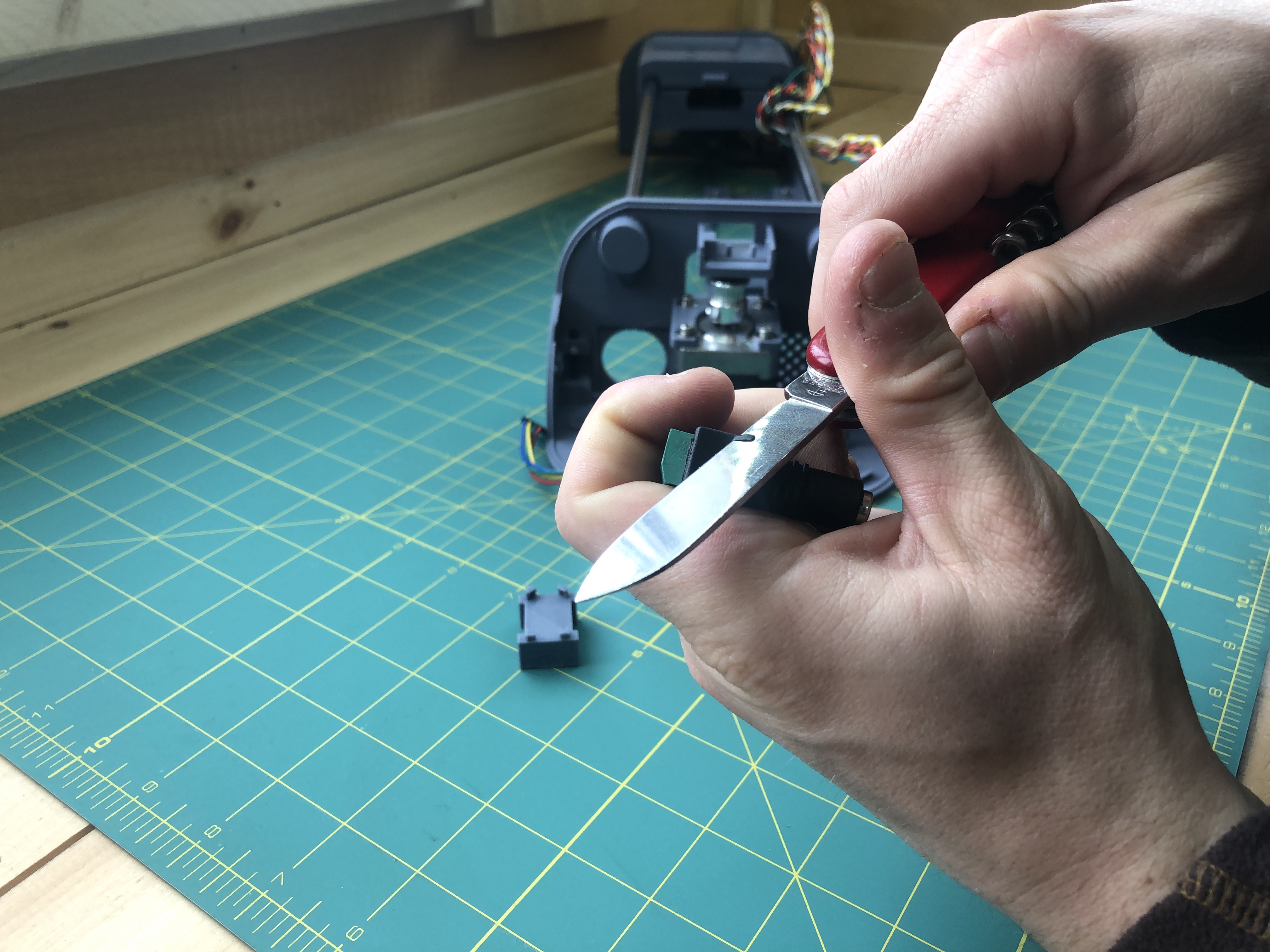
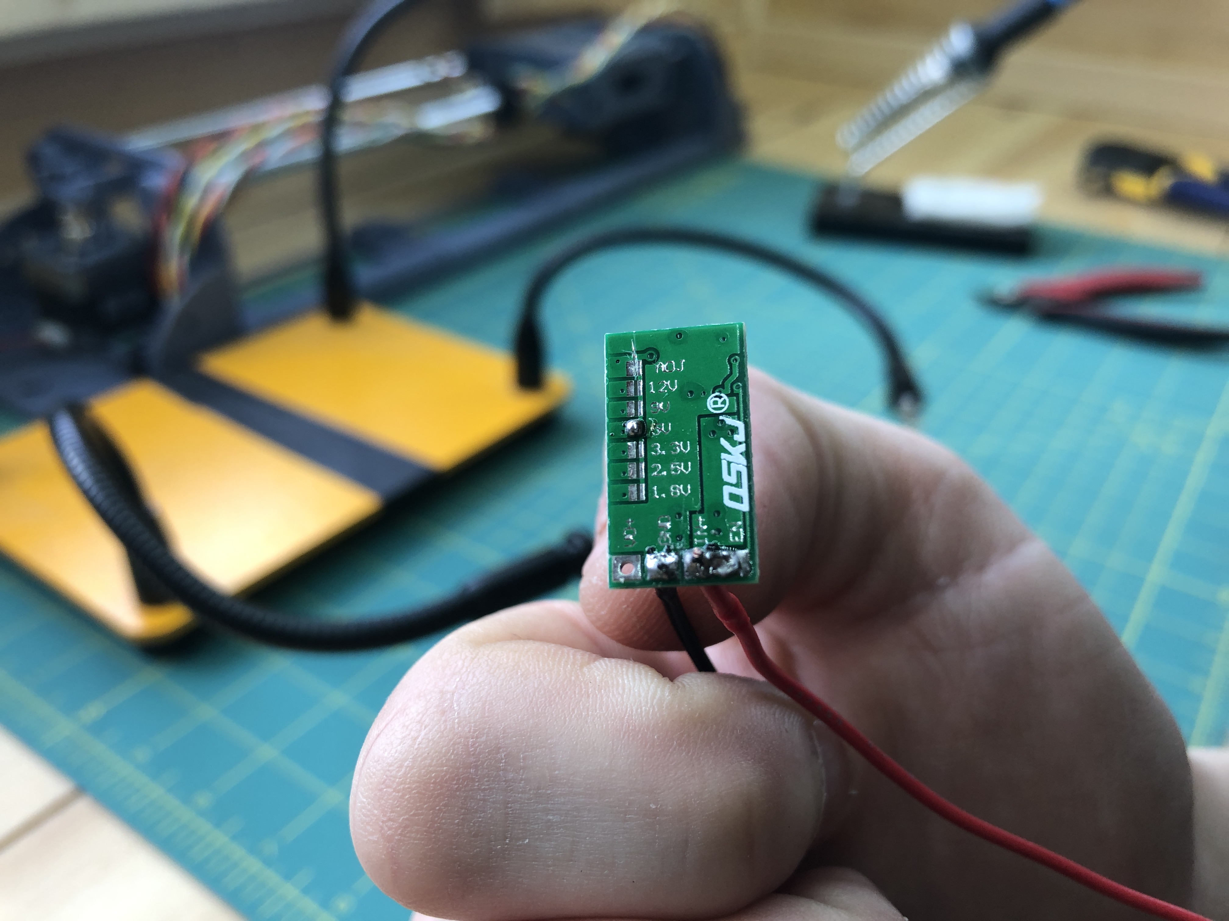
Take your voltage regulator, it needs to be set to turn 12V into 5V. We’ll tell it to not use the adjuster (a tiny rotating potentiometer on the other side), and instead hard set it to 5V to supply power to the Raspberry Pi. Definitely zoom in on the next picture to see exactly what to do.
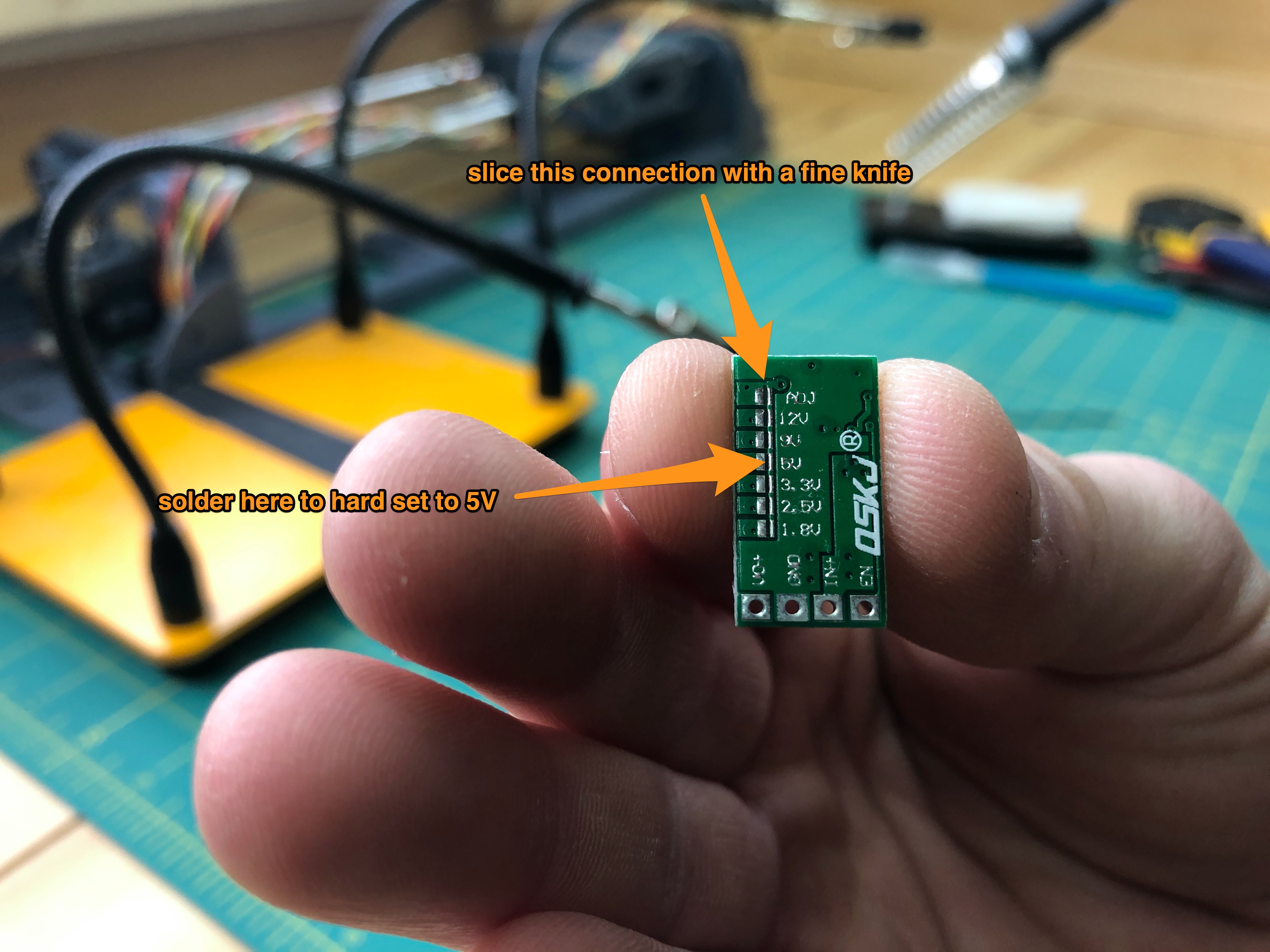
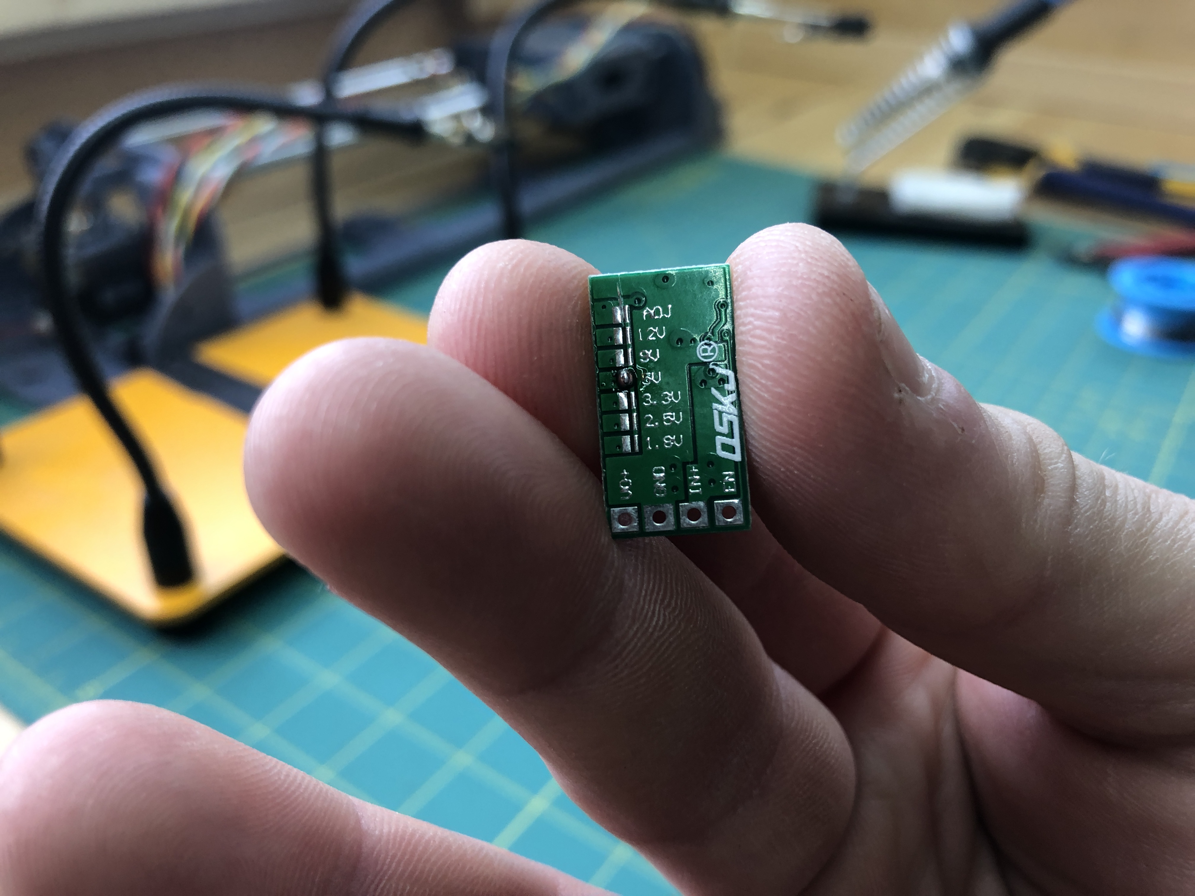
After a little work with the exacto knife and the soldering iron.
Grab a new black wire (not one already in the plotter), strip it and solder it to the GND. I have this wonderful tool to strip wires.
Grab another new red wire and wire it into IN+. When you do so, also join IN+ with EN. It will make the voltage regulator always enabled.
I am not a good solderer and if it works, I’m all right with it :).
Grab a couple more red wires and a black one long enough to travel from the 12V power supply female connector to various parts of the terminal (plus some slack, it’s always easier to shorten a wire than to lengthen it). Also pull out from the umbilical of twisted wires joining both terminal the red/orange/black bundle.
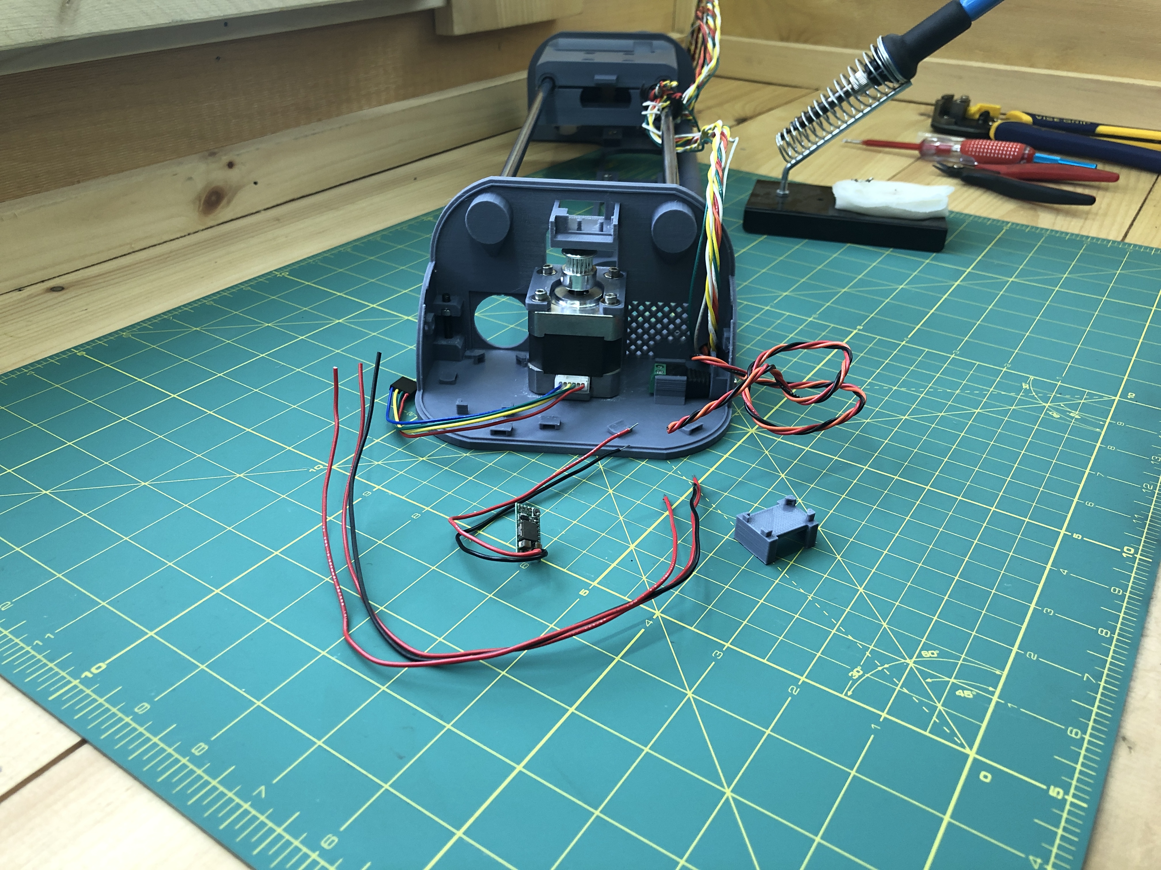
Solder the orange wire from the bundle into VO+ of the voltage regulator.
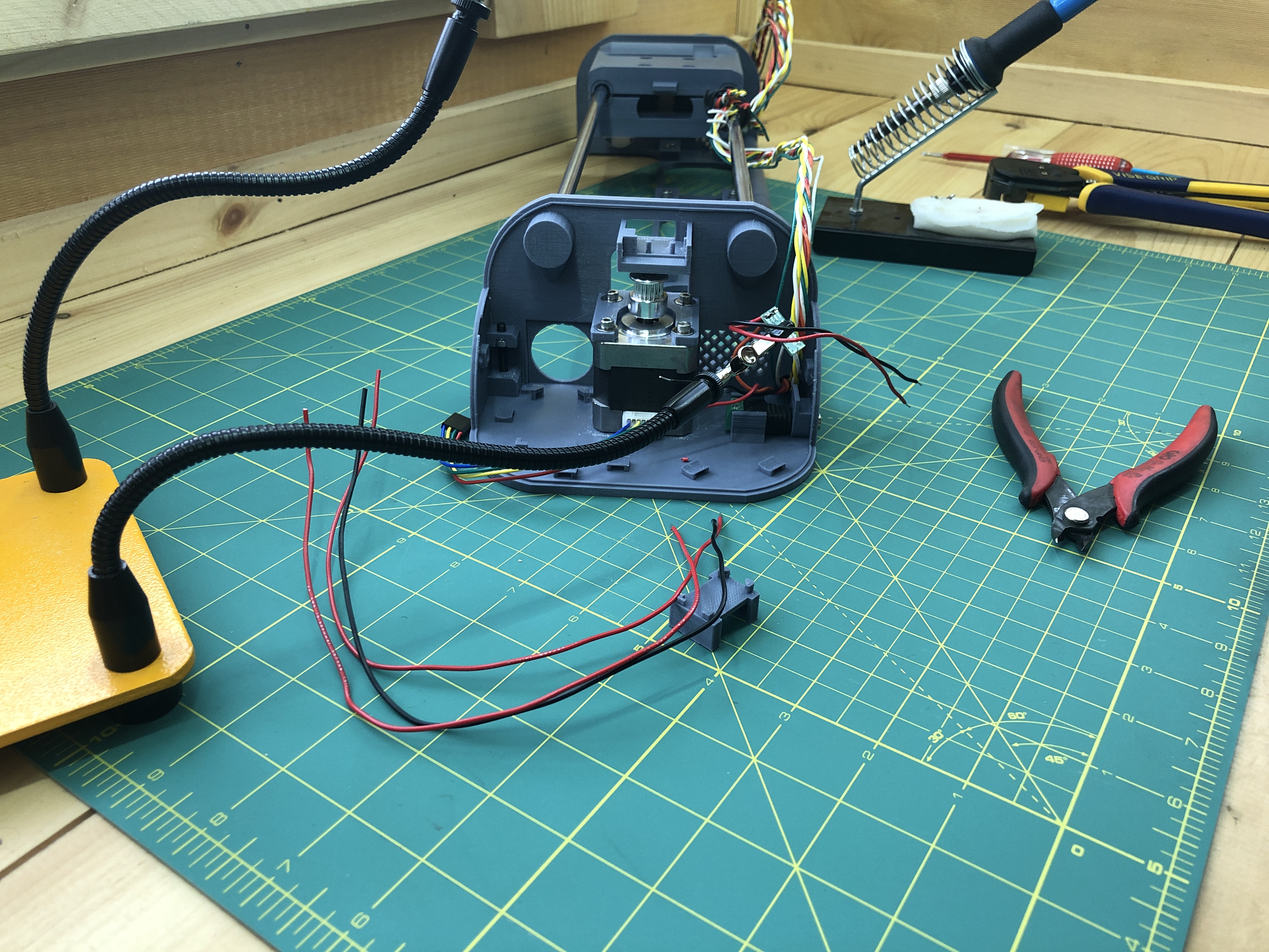
Unscrew both screws of the 12V power supply female connector to ready it to take wires.
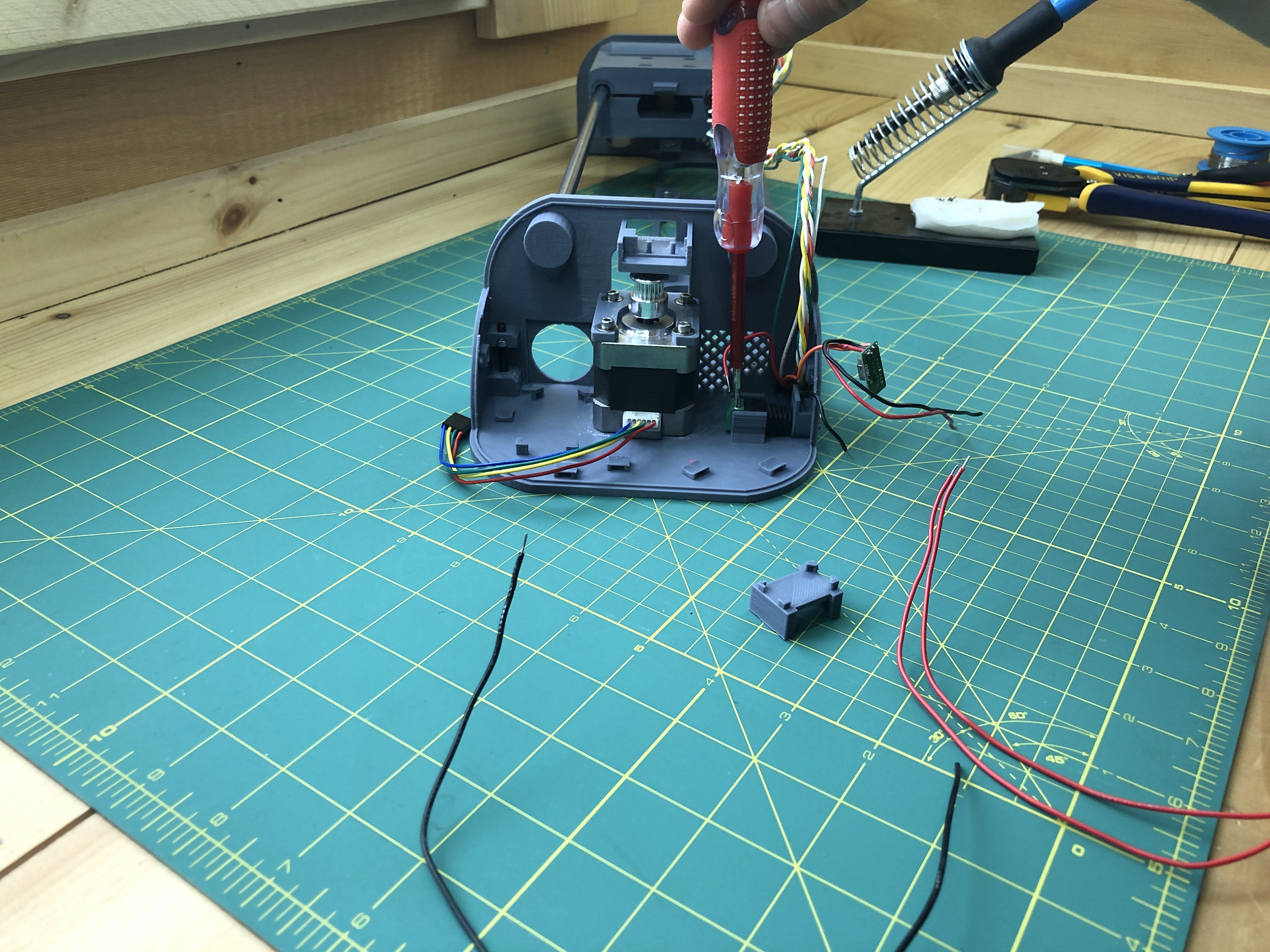
Insert into the 12V+ side, the red wire from the red/orange/black bundle, the red wire from the voltage regulator, and the 2 new red wires you made. That is 4 red wires total on the 12V+ side.
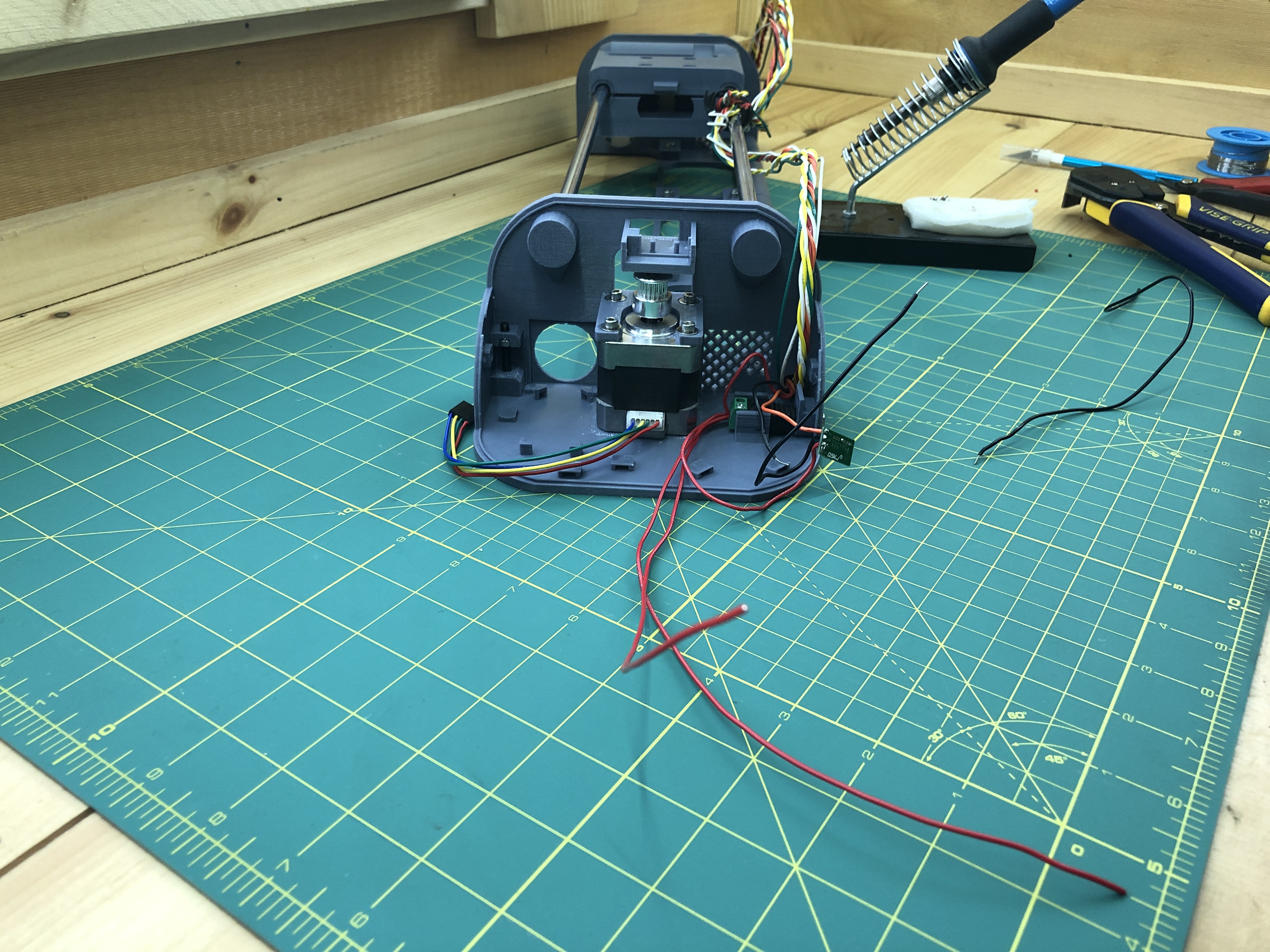
On the Ground side, insert the black wire from the red/orange/black bundle, the black wire from the voltage regulator, and the 1 new black wire you made. That is 3 black wires total on the ground side.
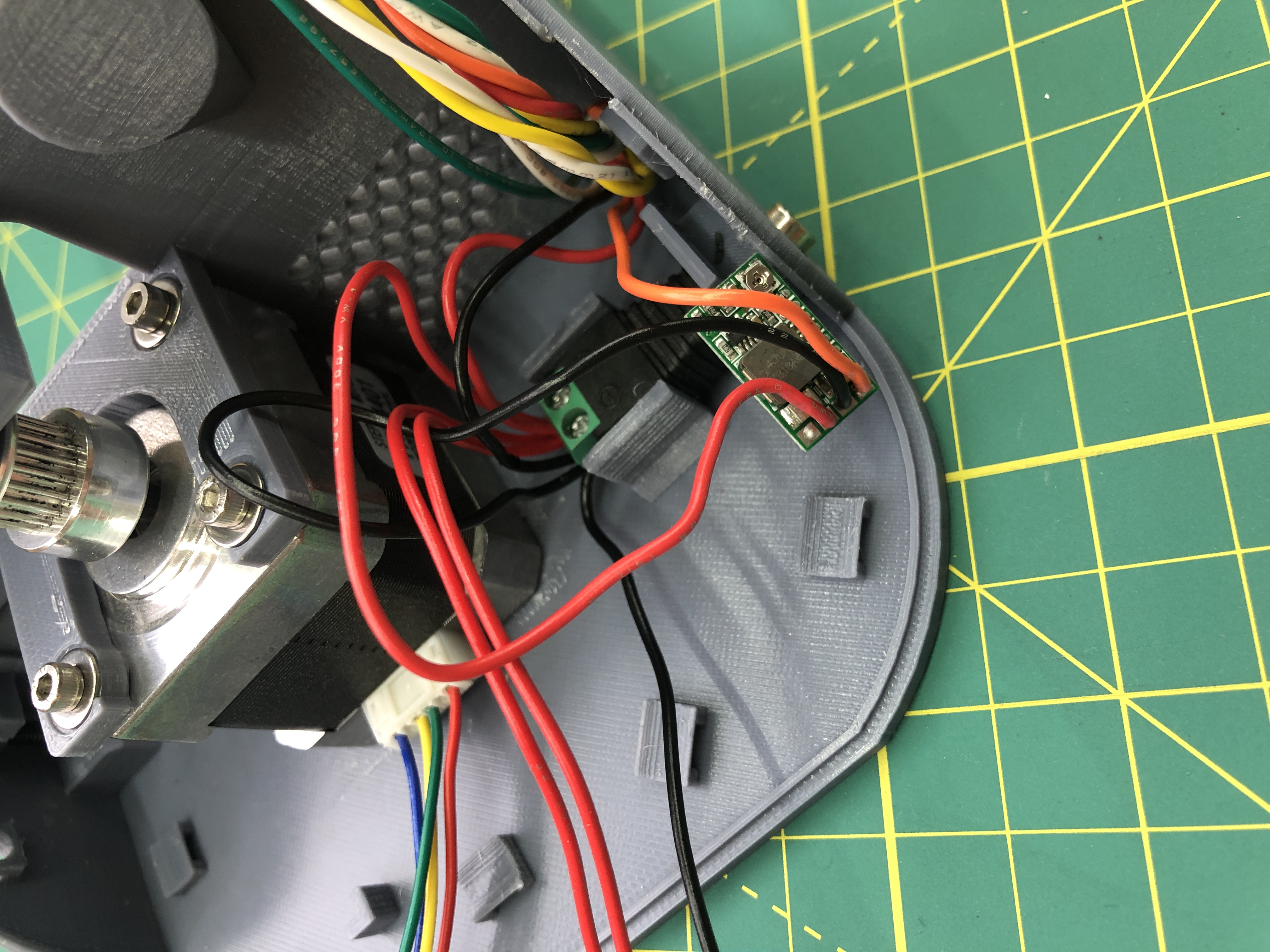
Here’s what this will look like when this is done schematically.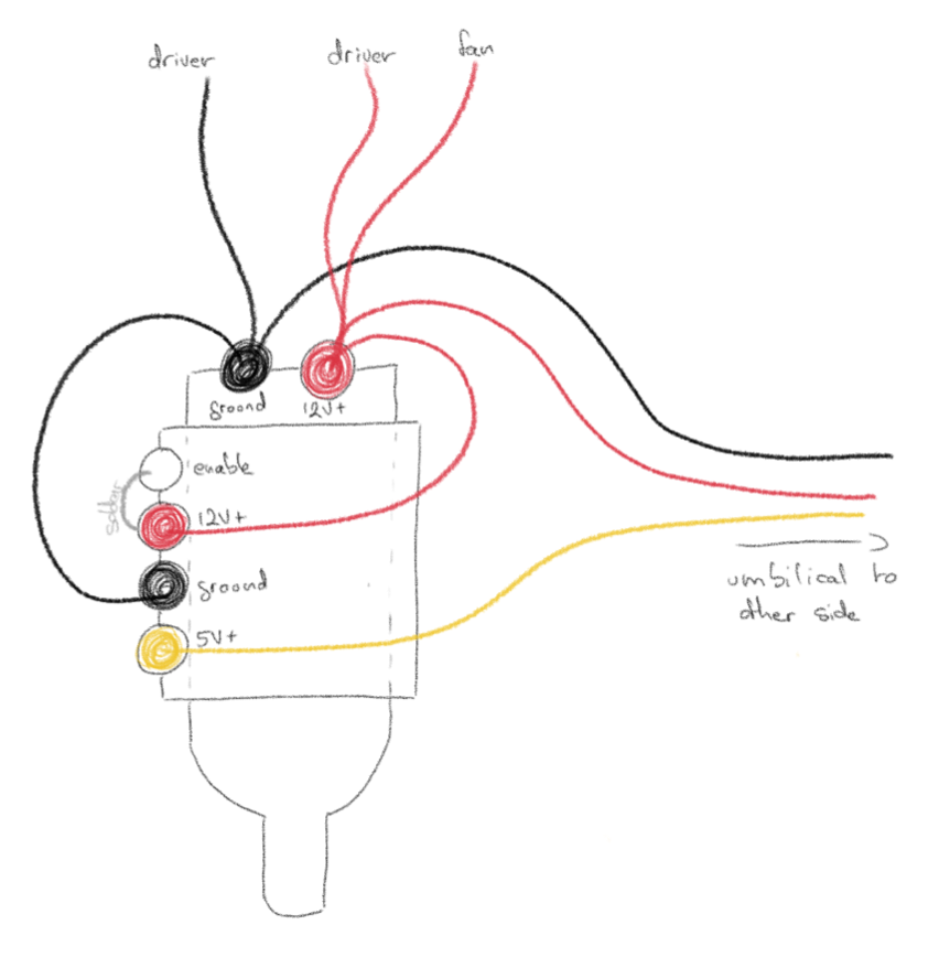
And with the usual photos.
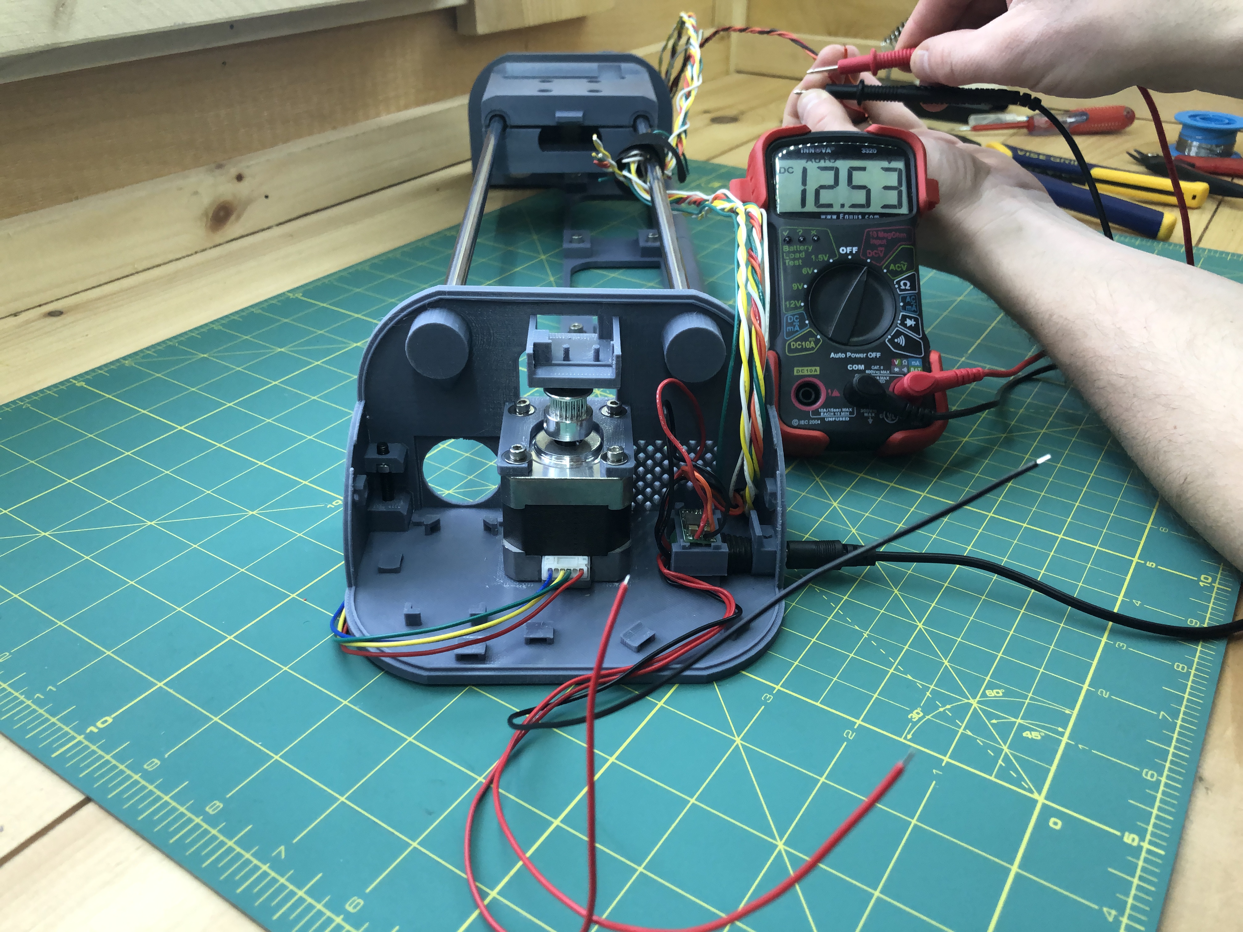
Let’s plug the plotter into a source of power and make sure that we get the proper voltages where we think we have them. Every red/black combo should give us approximately 12V (emphasis on the approximately).
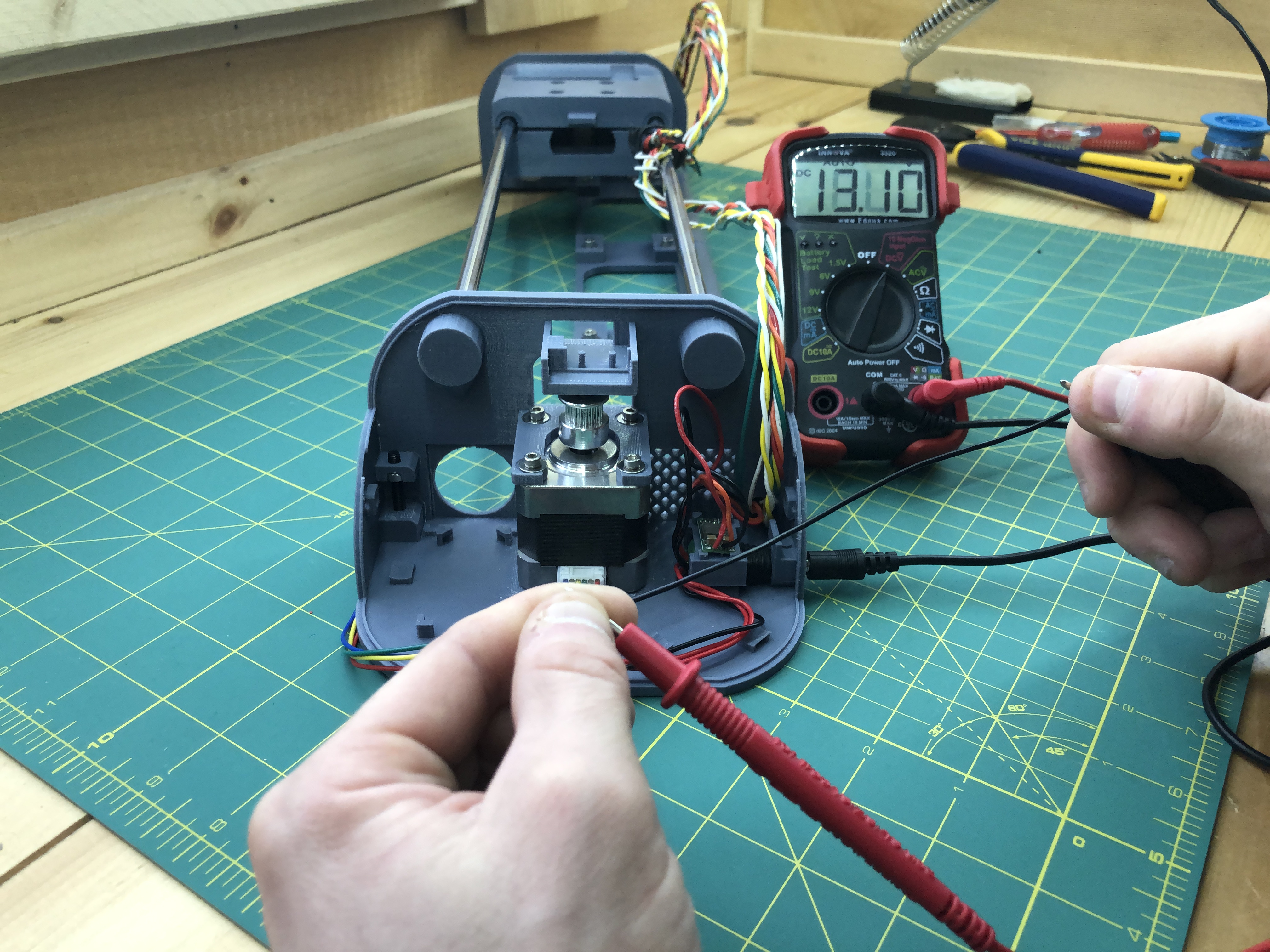
Even at the opposite terminal.
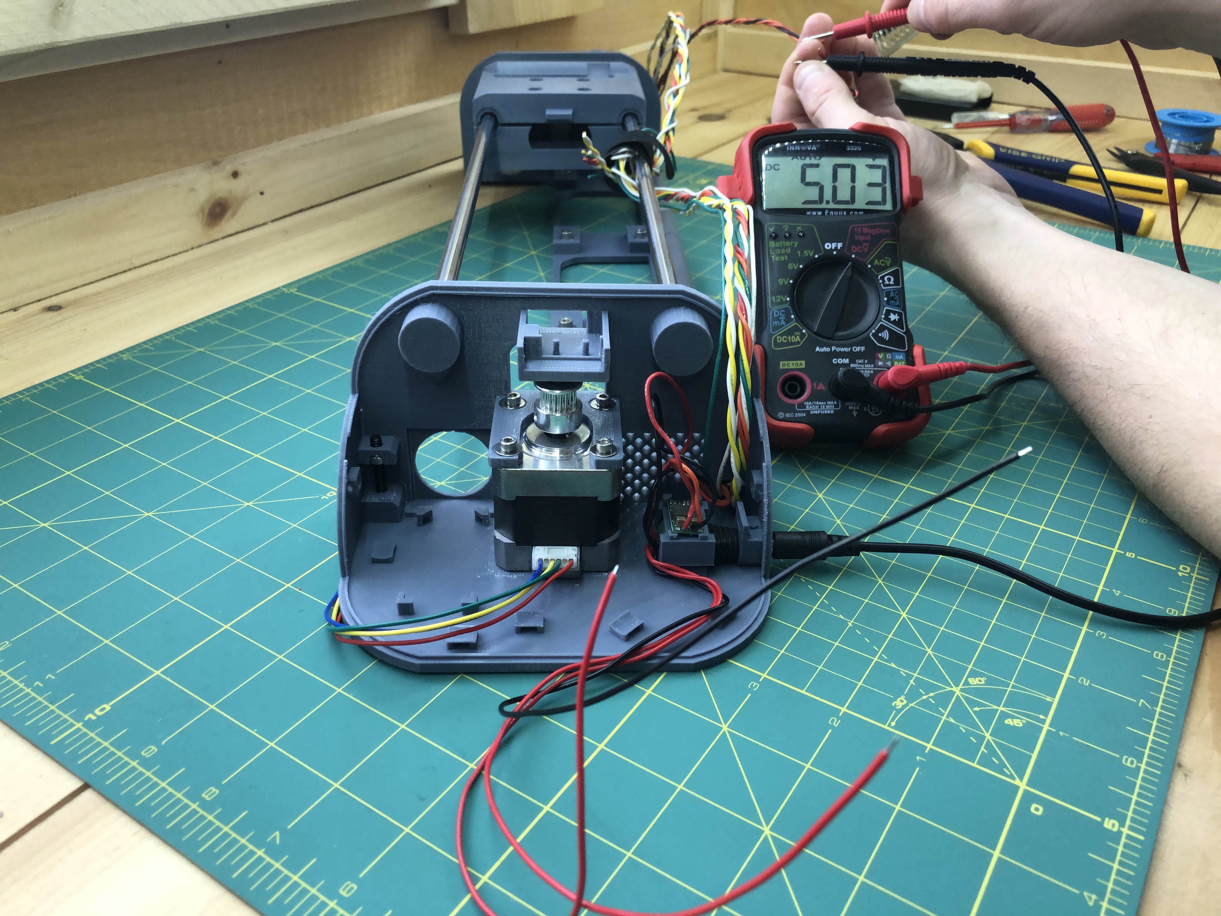
Also at the opposite terminal, the orange/black pair from our power bundle should give us 5V. This is what we’ll use to power the Pi.
When you are satisfied that it all looks good, put some electrician tape at the tip of these wires to be safe. We won’t use all of them immediately.
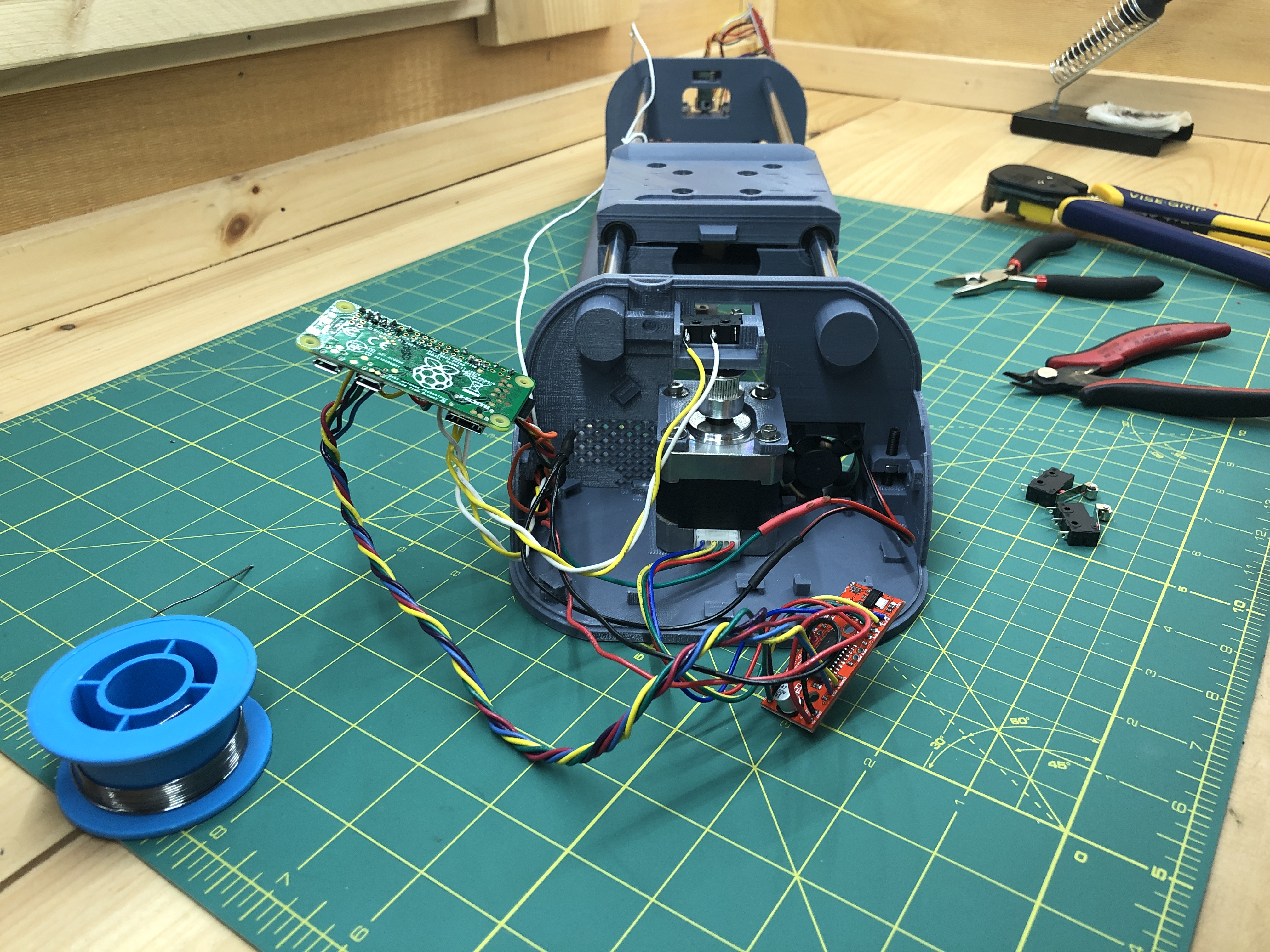
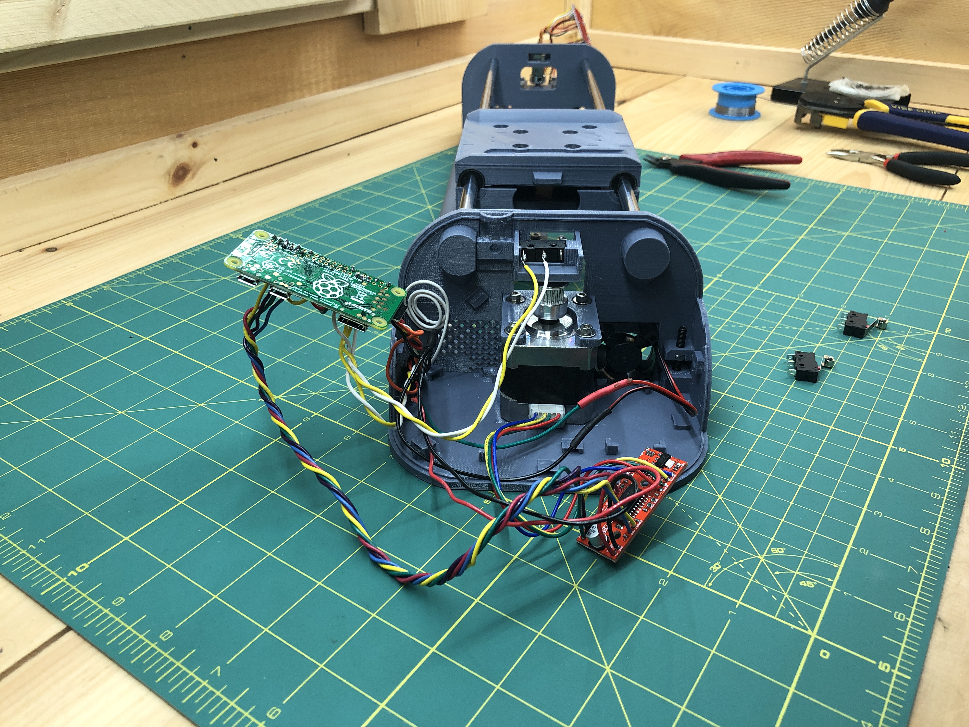
6. Raspberry Pi
We’re going to get the Pi going so we can test components as we add them to our build (stepper motors, limit switches & servo motor).
Download the PlottyBot SD card image
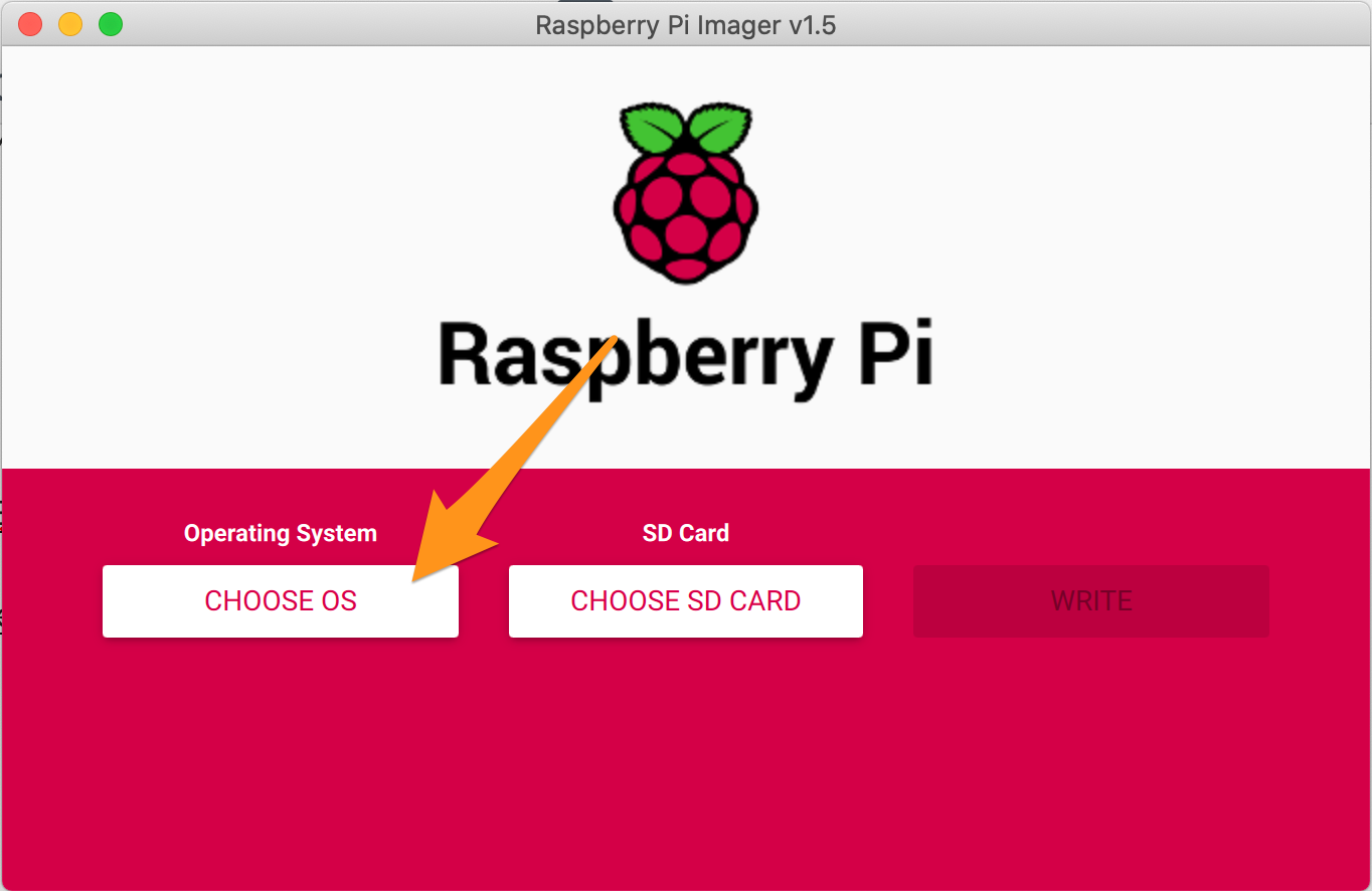
Then download the Raspberry Pi Imager which we’ll use to write the image onto your SD card.
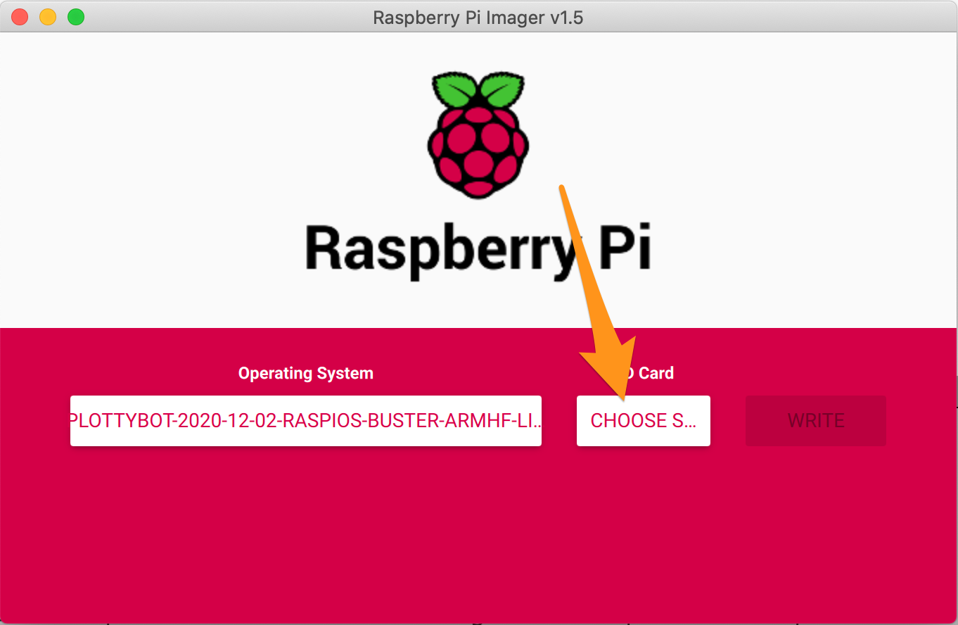
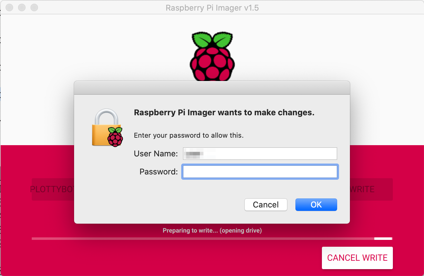
Launch the Raspberry Pi Imager and follow these steps:
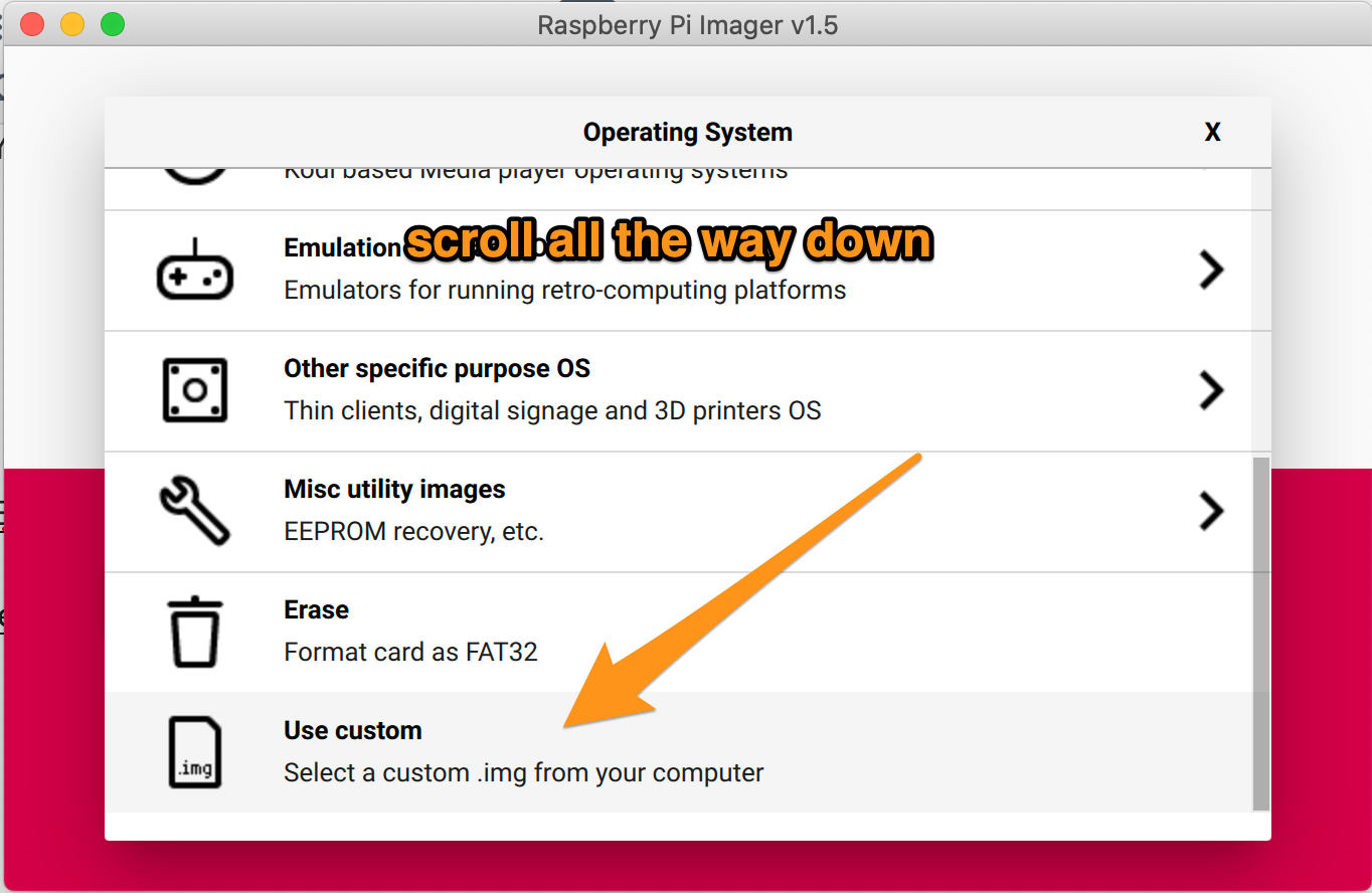
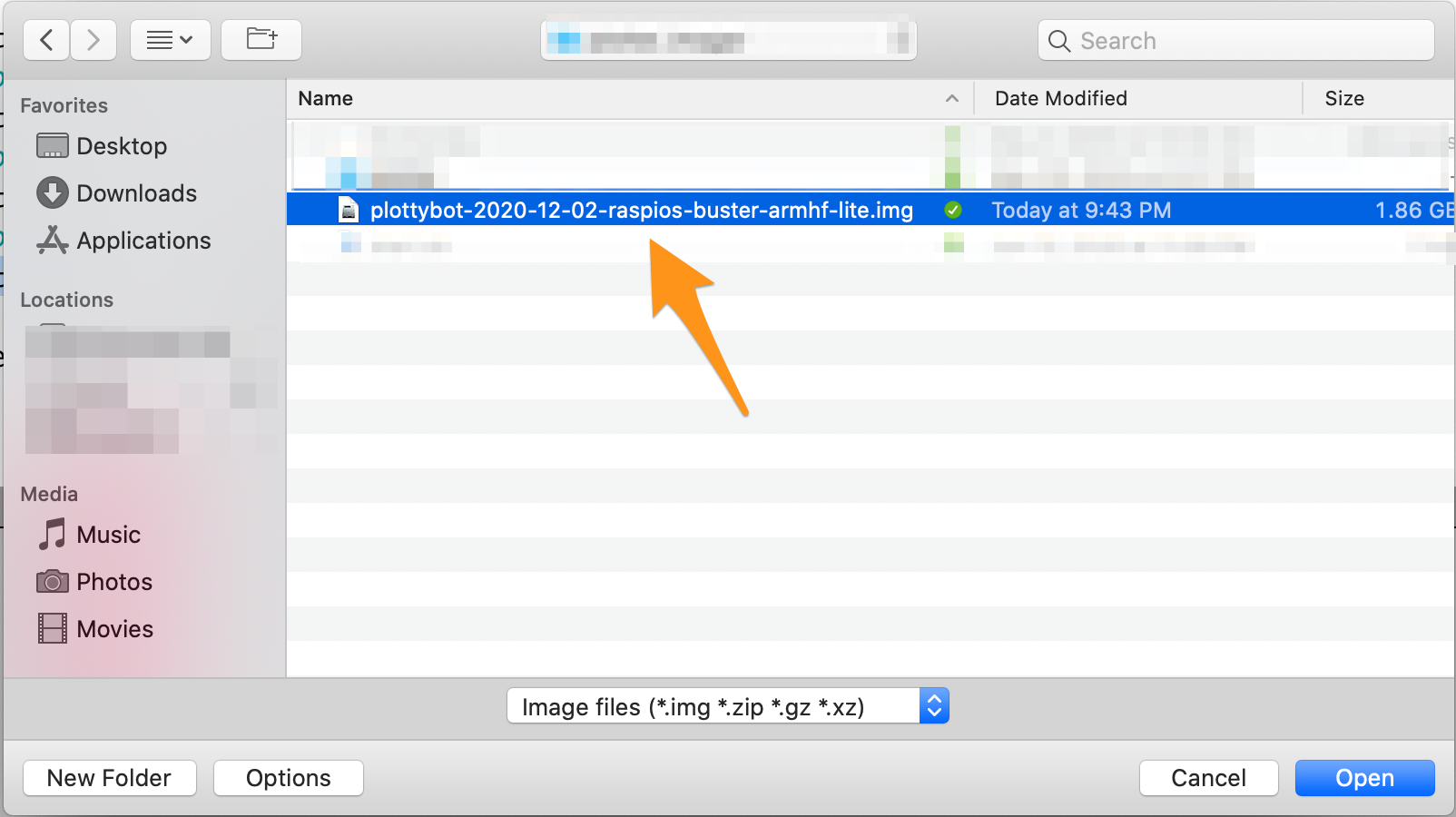
Find the PlottyBot SD card image you just downloaded.
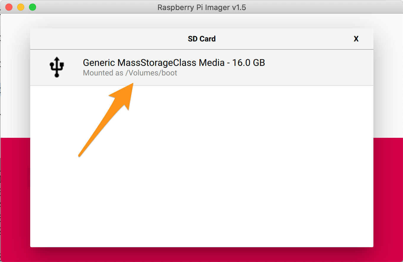
Make sure you pick the right SD card, if you have anything else show up in this list you want to triple check that you don’t overwrite something that is not the SD card for your Pi.
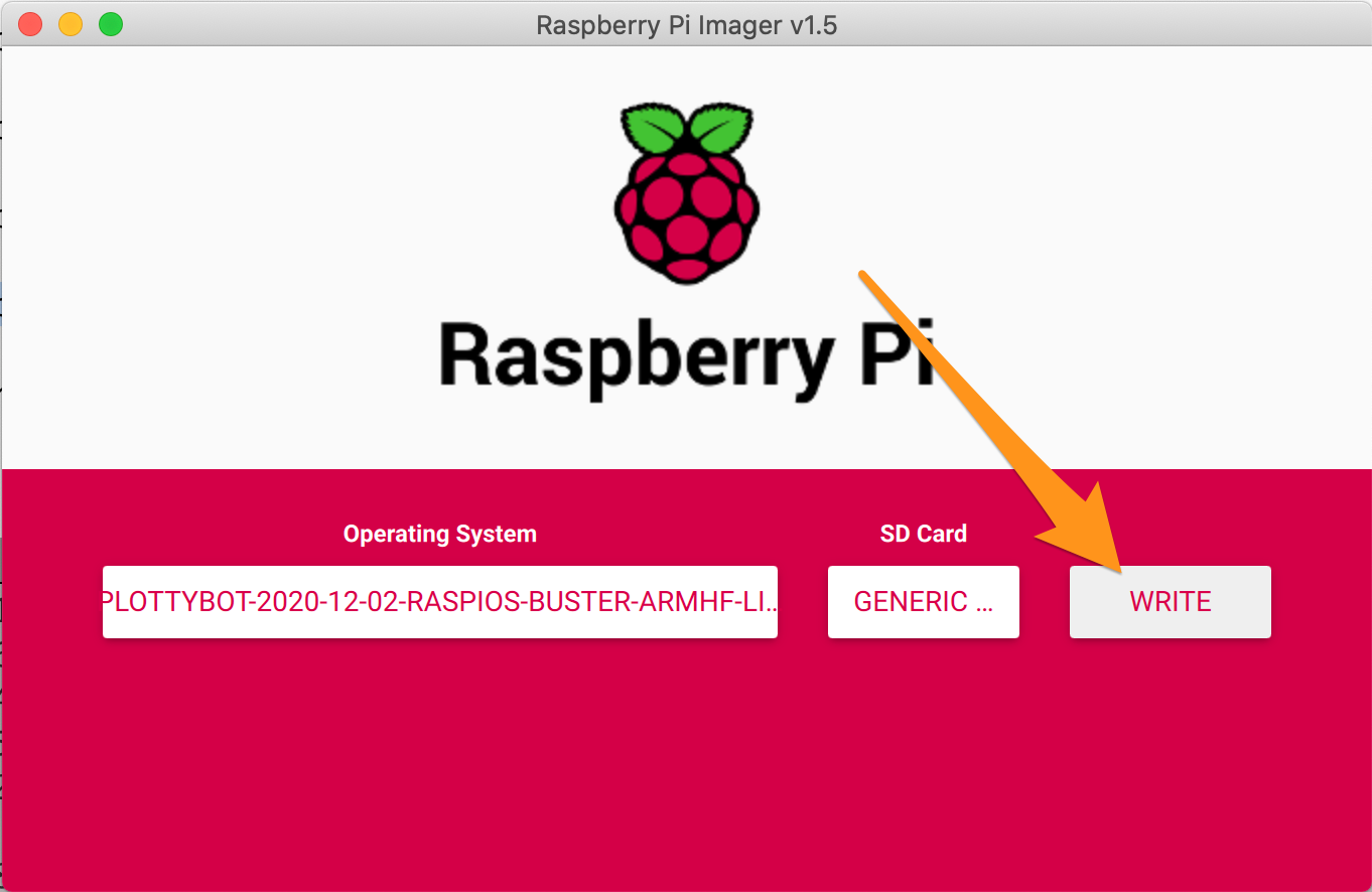
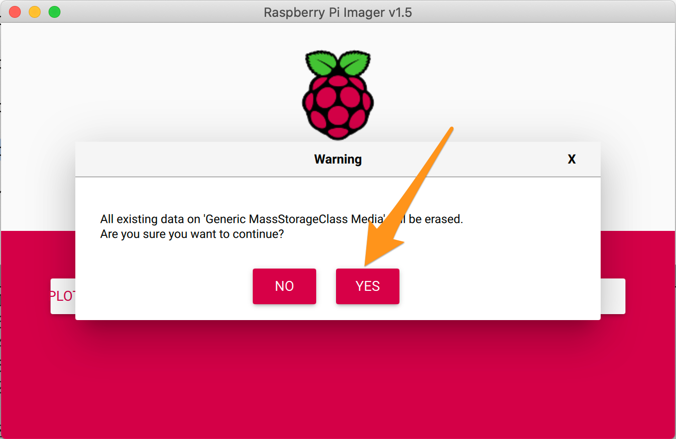
Elevated privileges are required.
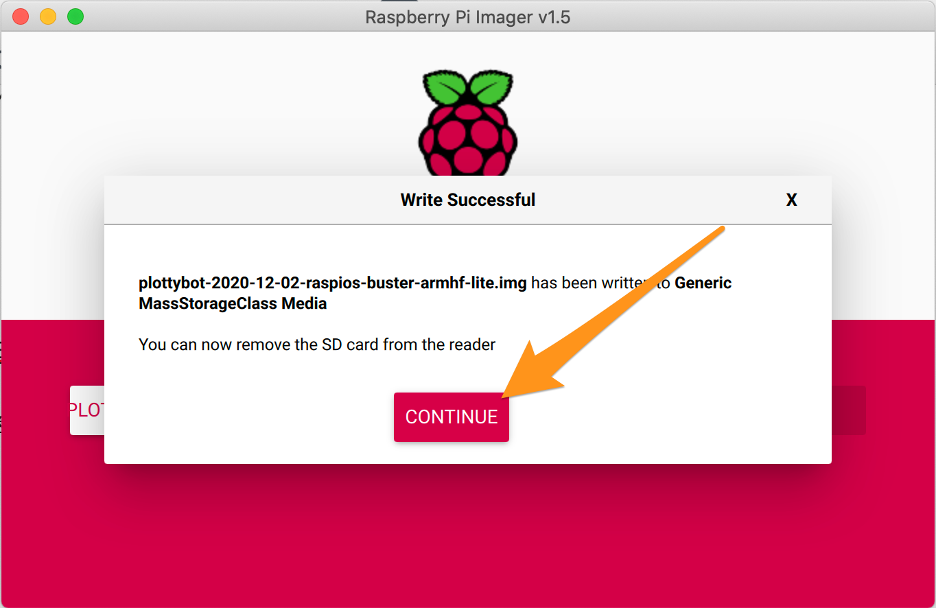
Put the SD card in your Pi and plug it in to a standard USB power source.
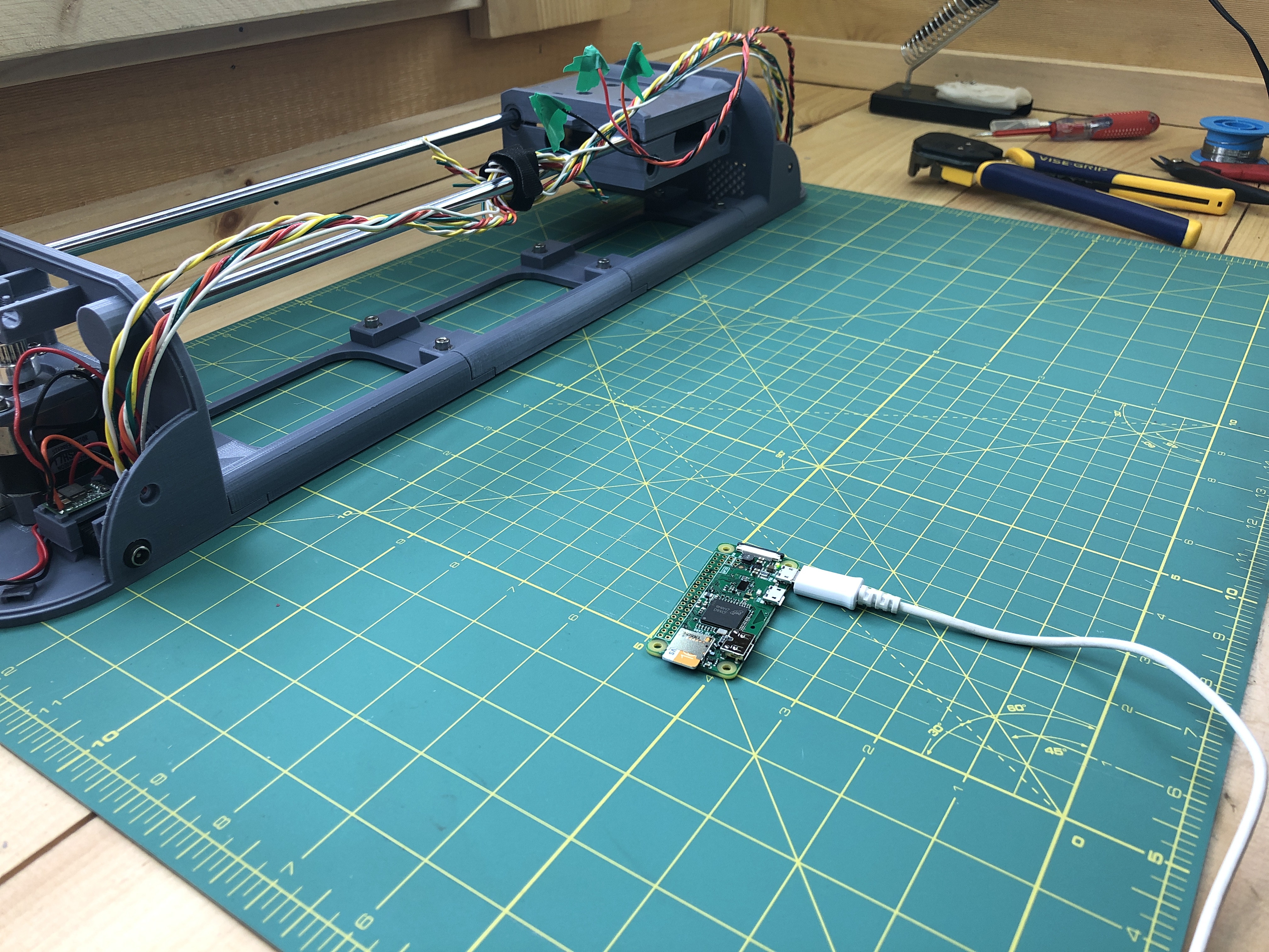
You can connect it to a screen too if you want but you don’t have to because we’ll connect to it via WiFi. Keep in mind however that the first time it boots, it will take 10 to 15 minutes to complete all the initialization steps. This is only the first time as it installs all the necessary packages to run the plotter. You’ll know it’s done when you see a new WiFi network called “PlottyBot”.
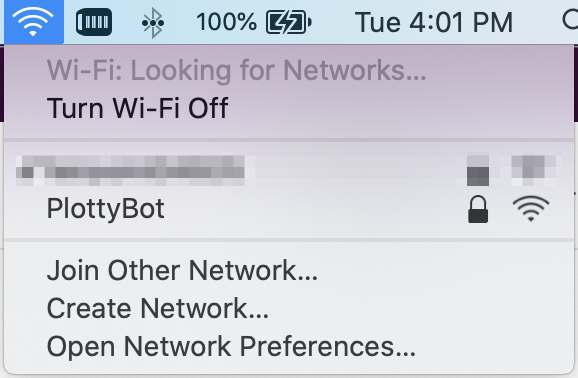
Go ahead and connect to it, the password is 1234567890 (you will no longer be connected to the internet, only to your PlottyBot). Then point your browser to http://plottybot.local. If plottybot.local doesn’t work, you can try going directly to http://10.0.0.5.
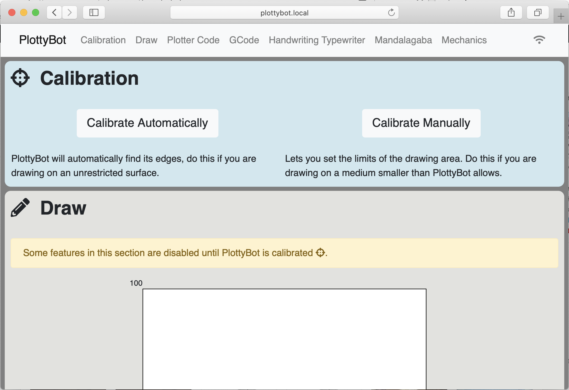
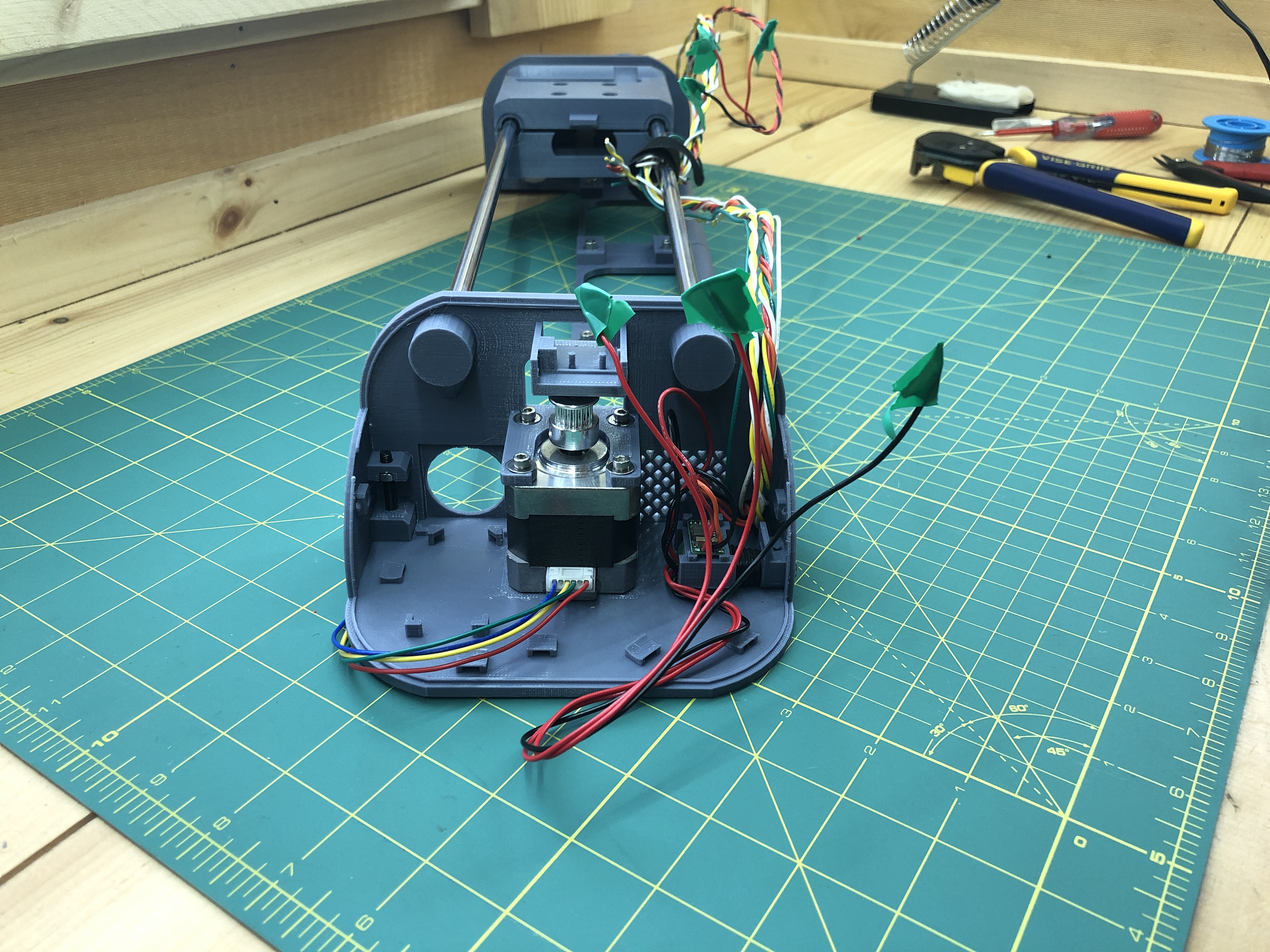
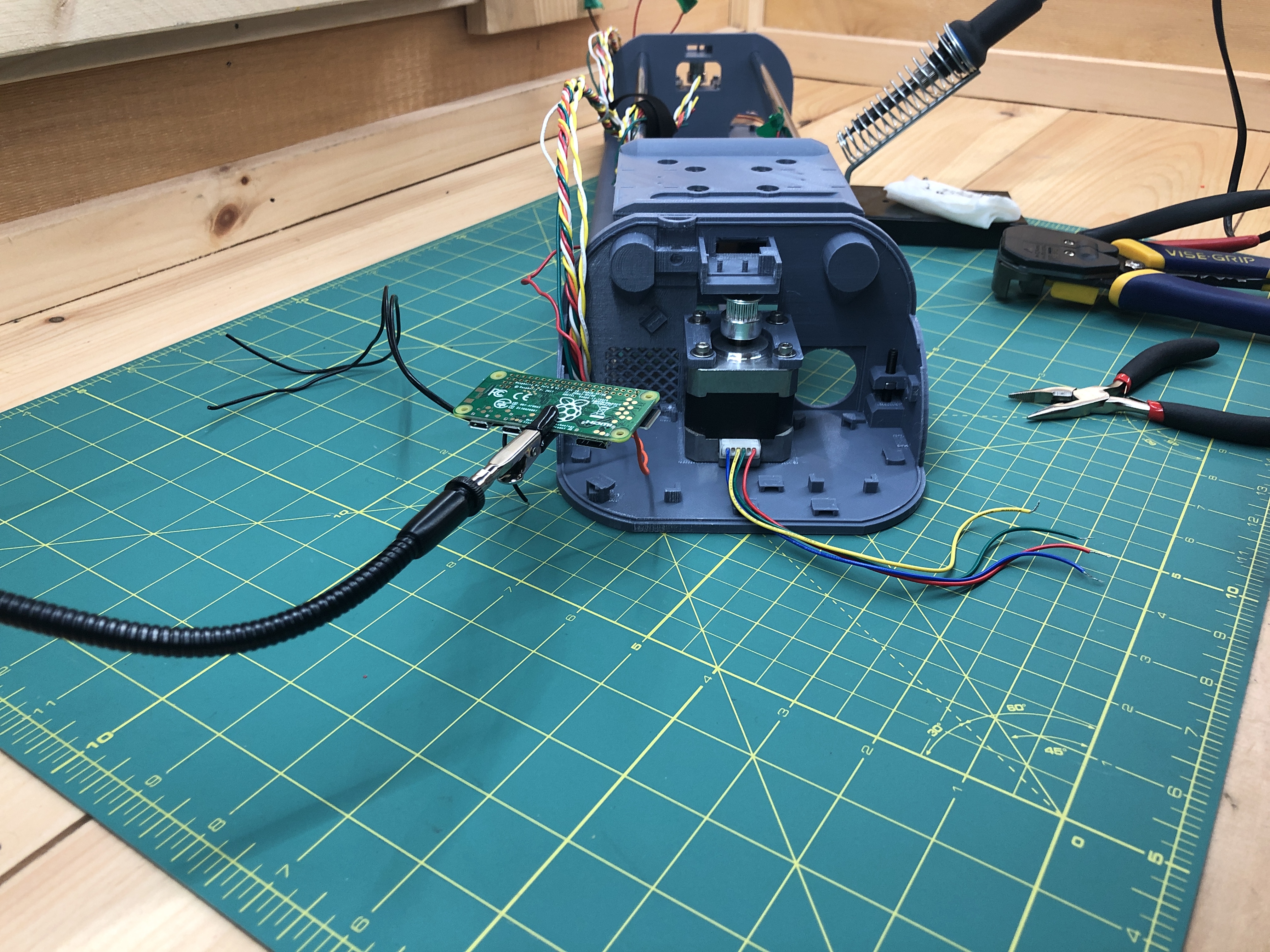
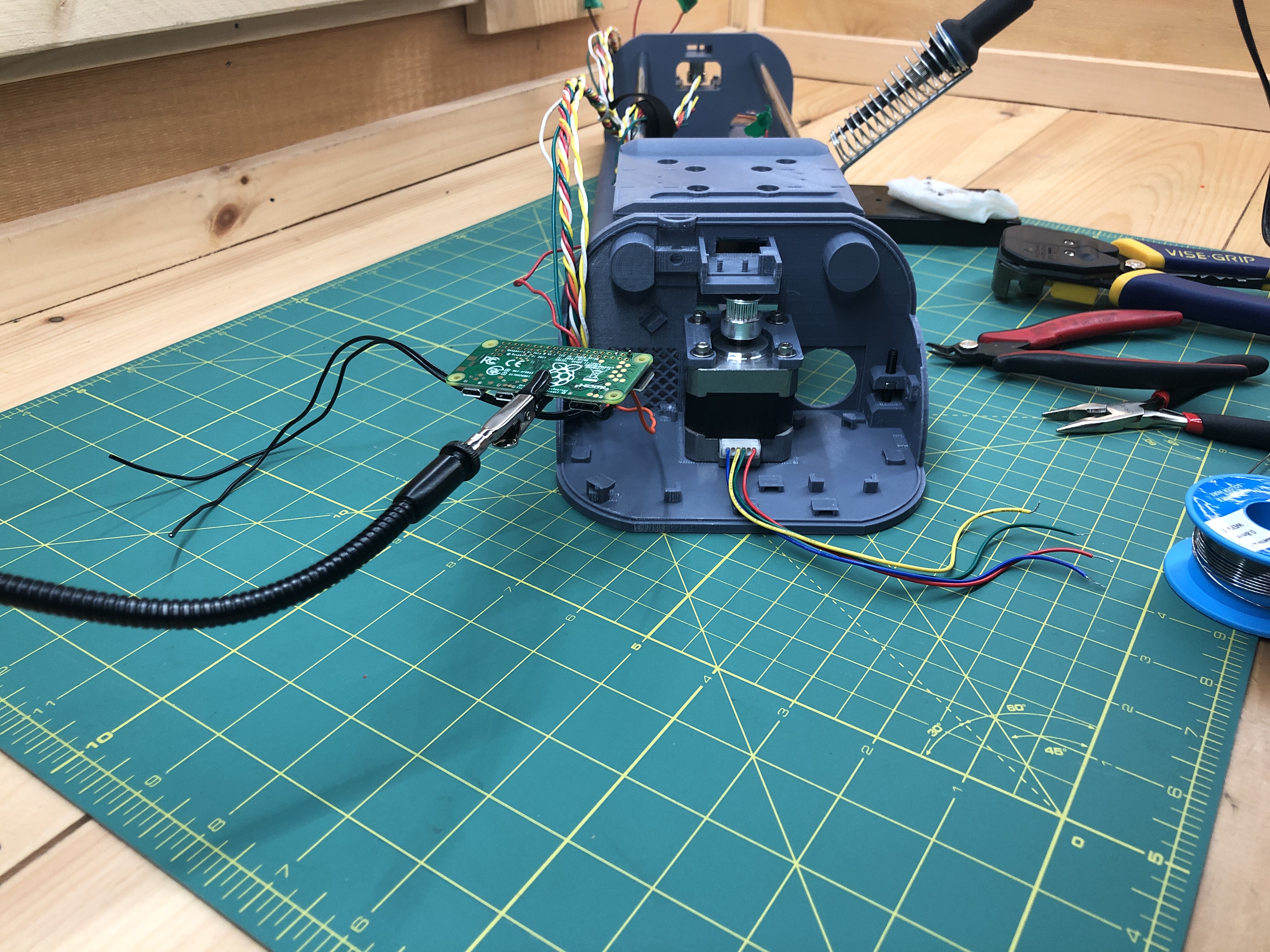
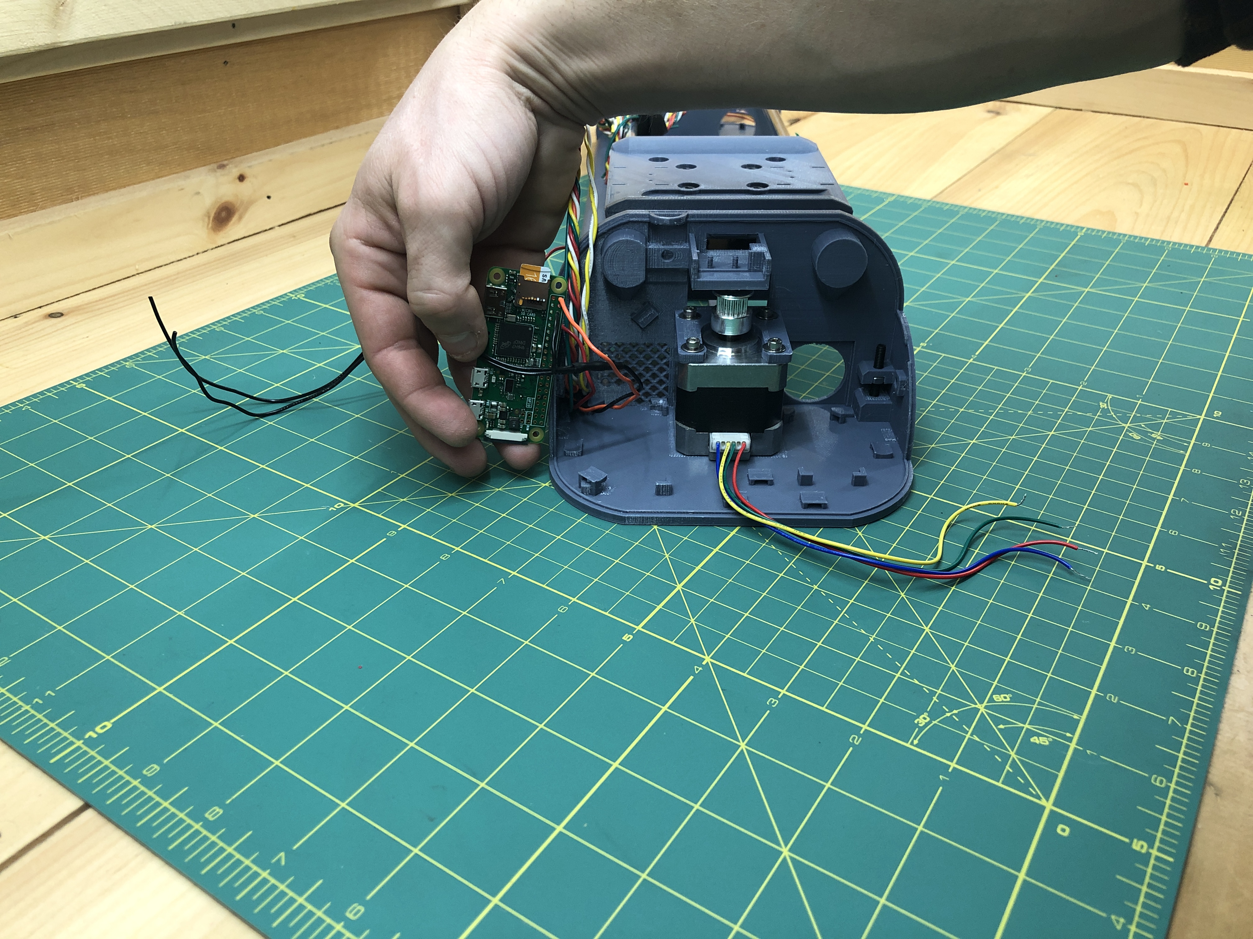
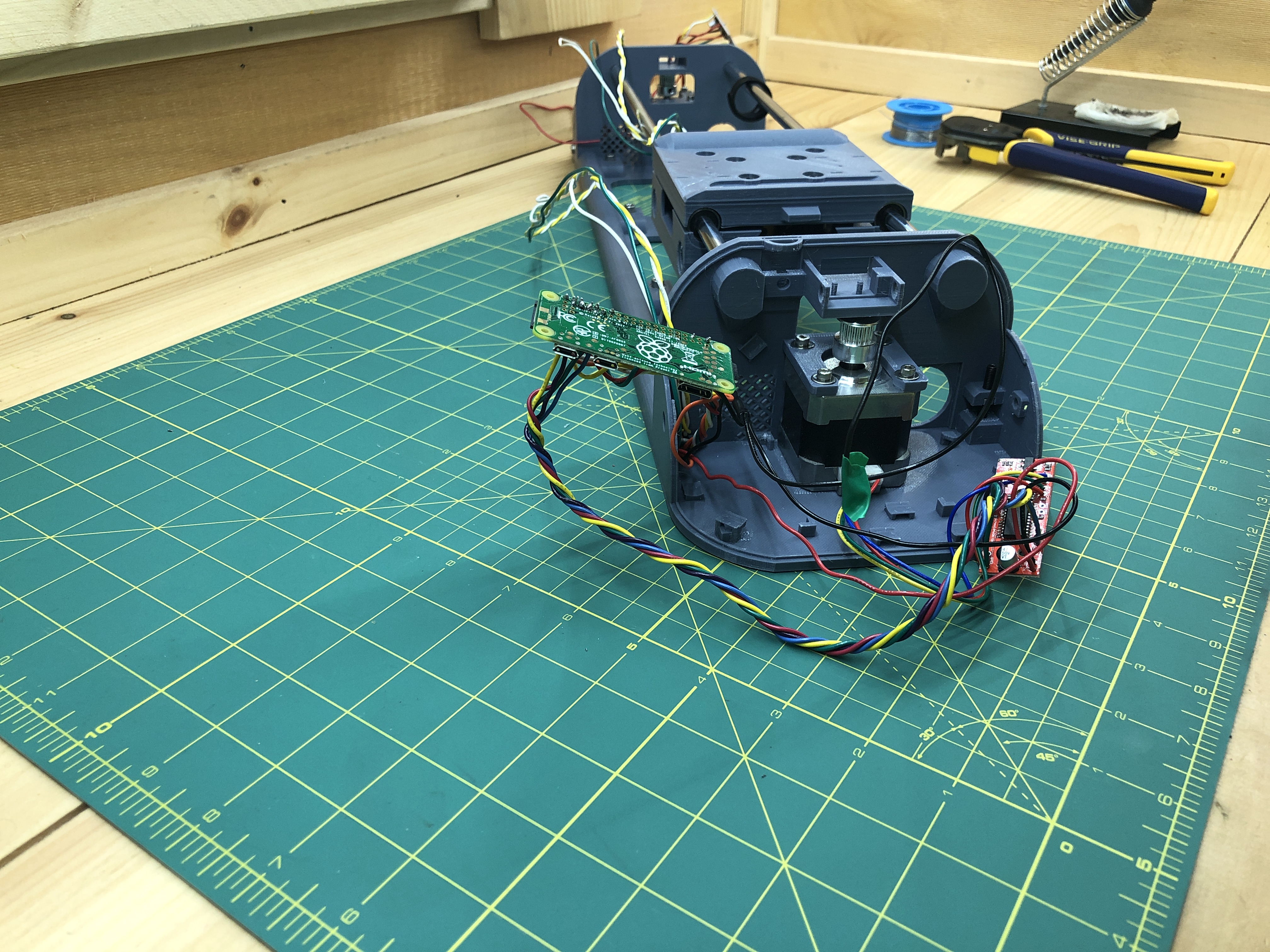
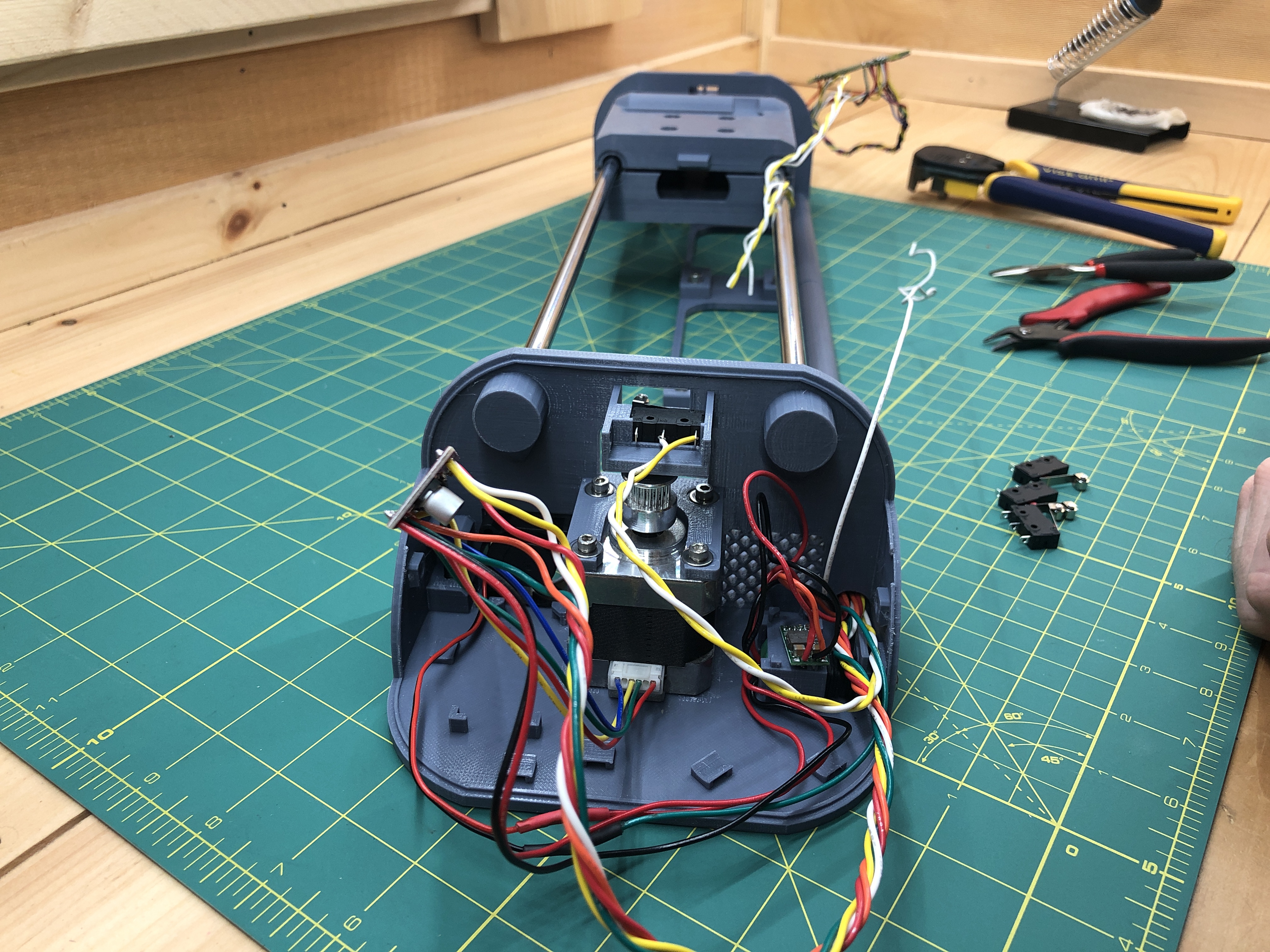
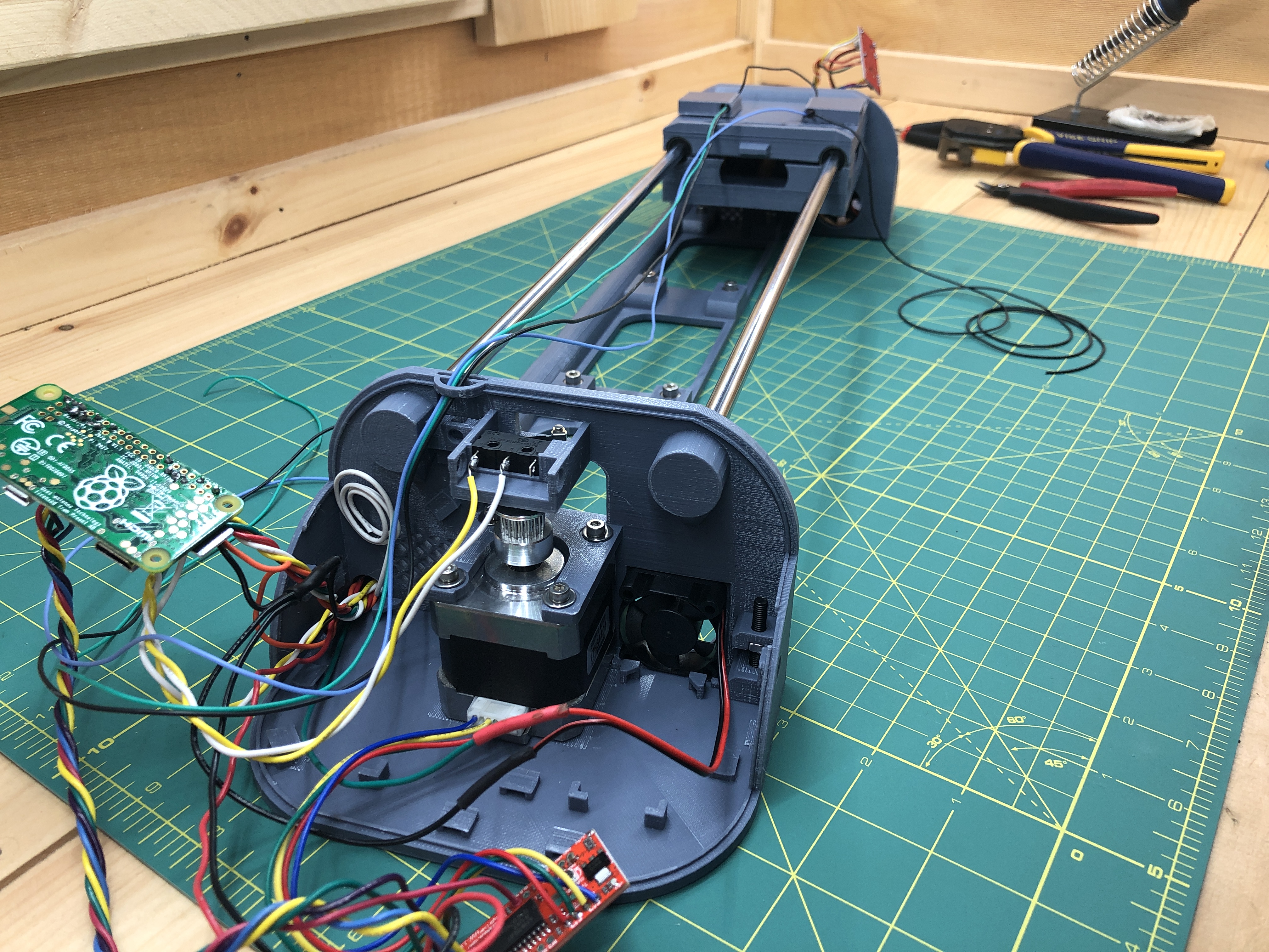
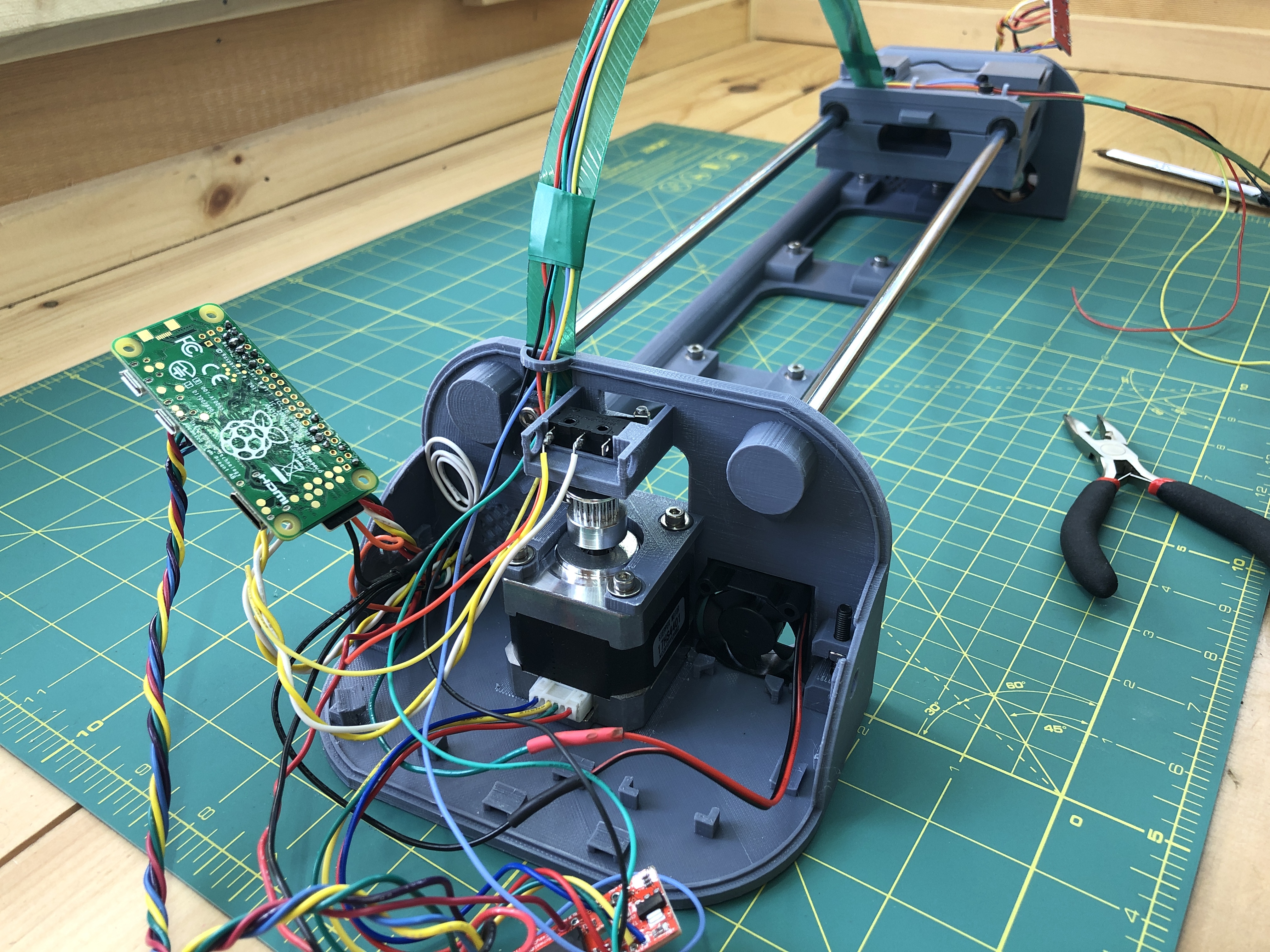
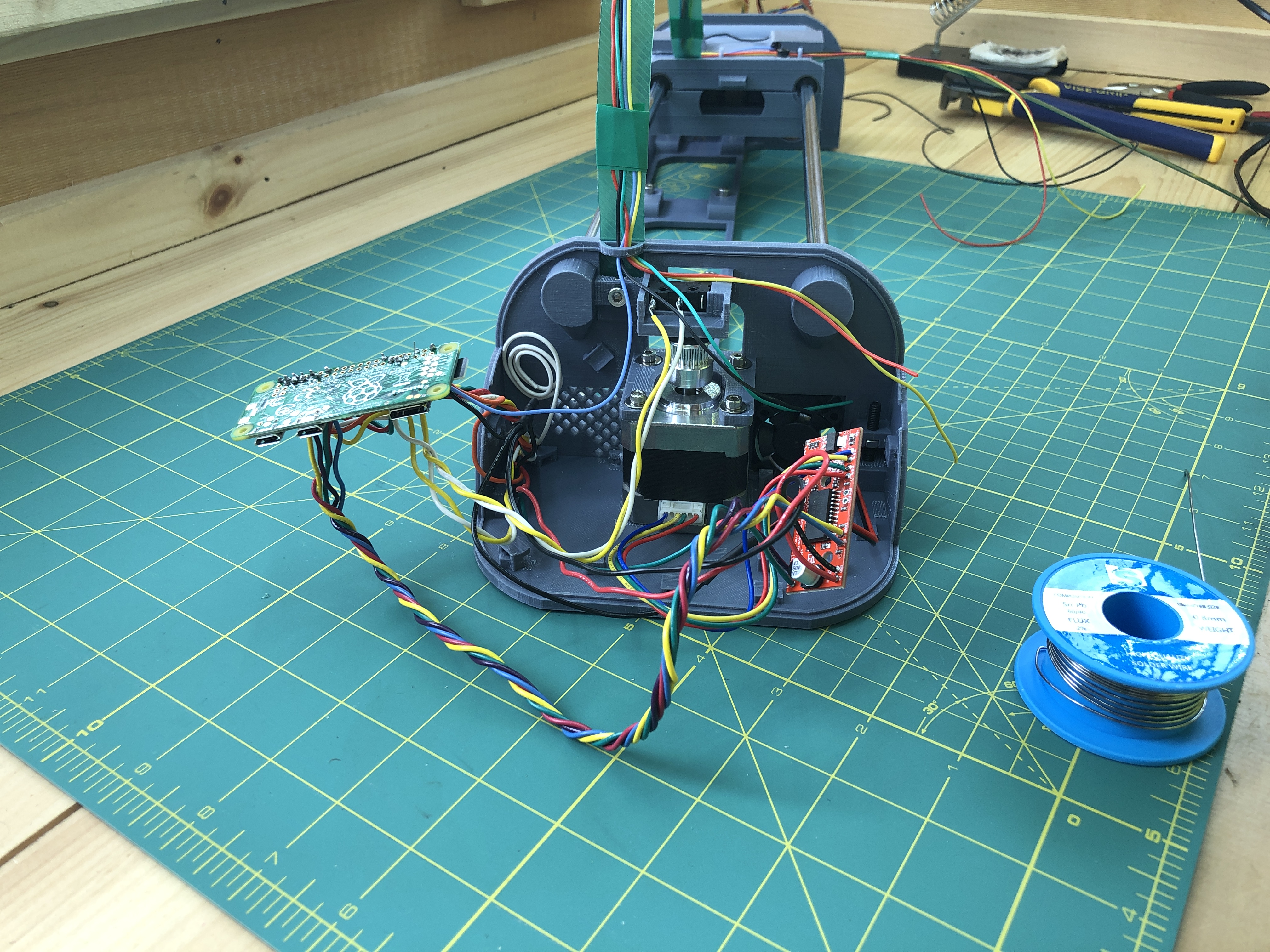
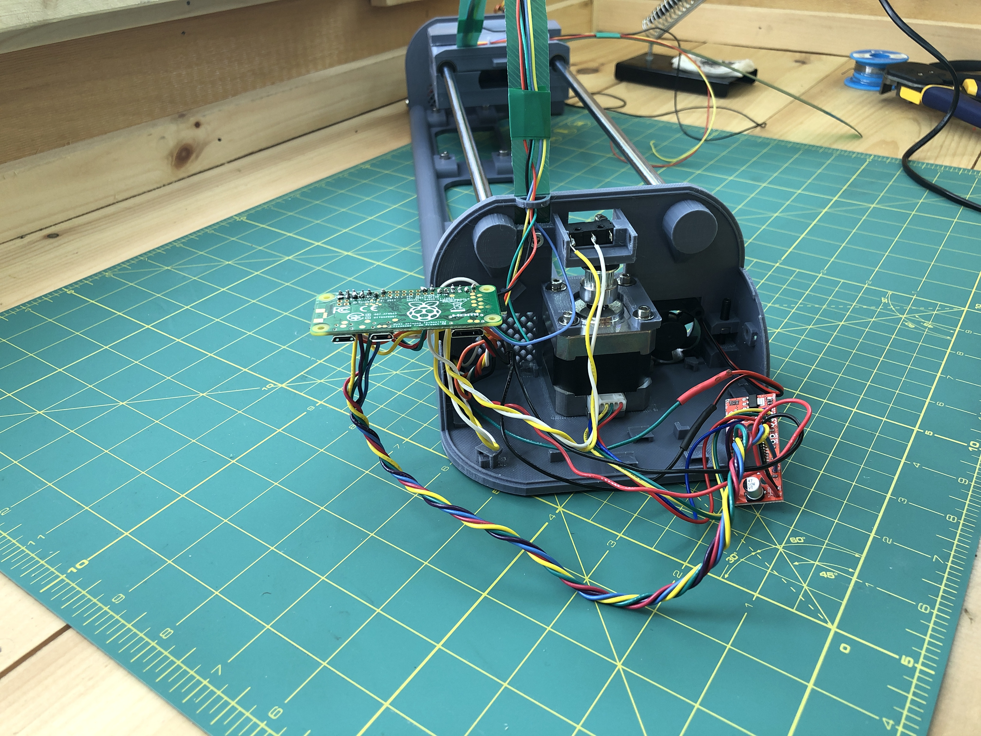
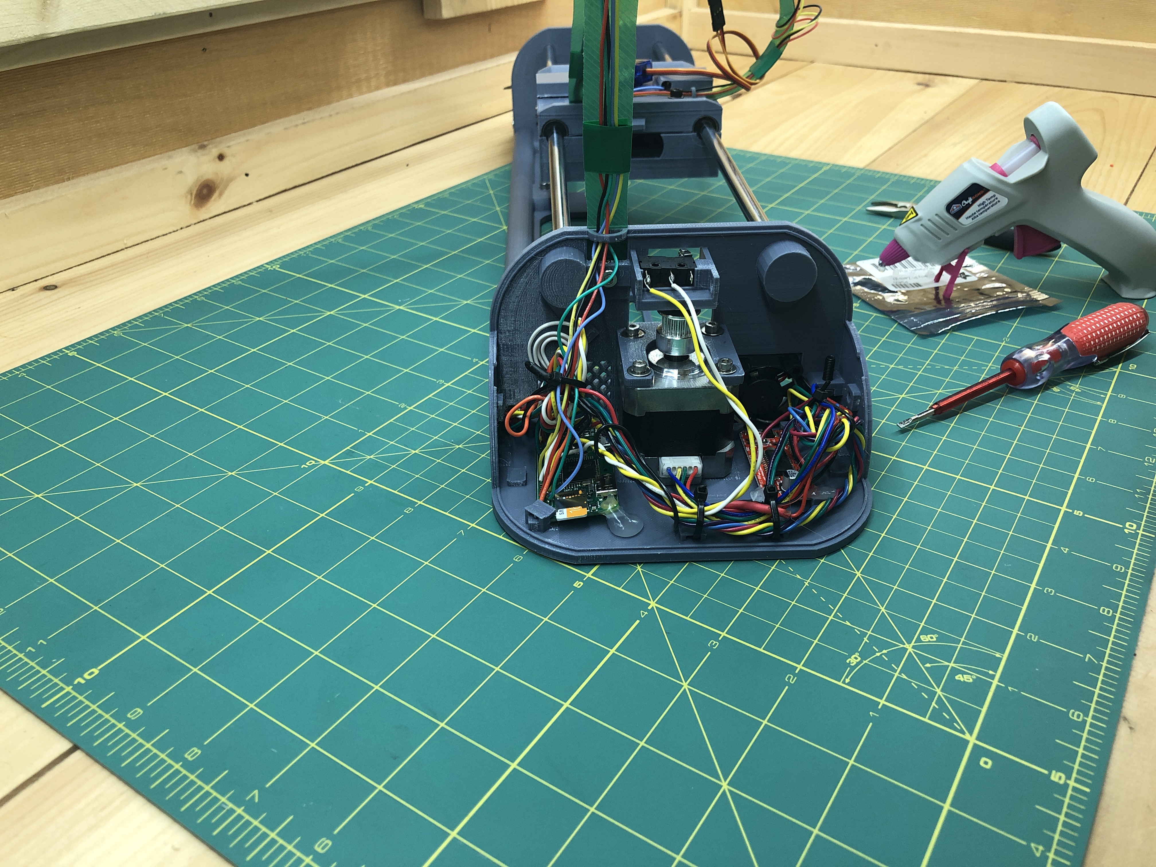
This is the web interface you will use to have your plotter do cool drawing projects for you. Because you’re seeing it, you know the Pi is ready to go in. It goes in the bottom terminal as such (here loosely fitted in its holder). Notice the red/orange/black wire bundle we’ll use to give it power.
Untwist your bundle a bit to work with it.
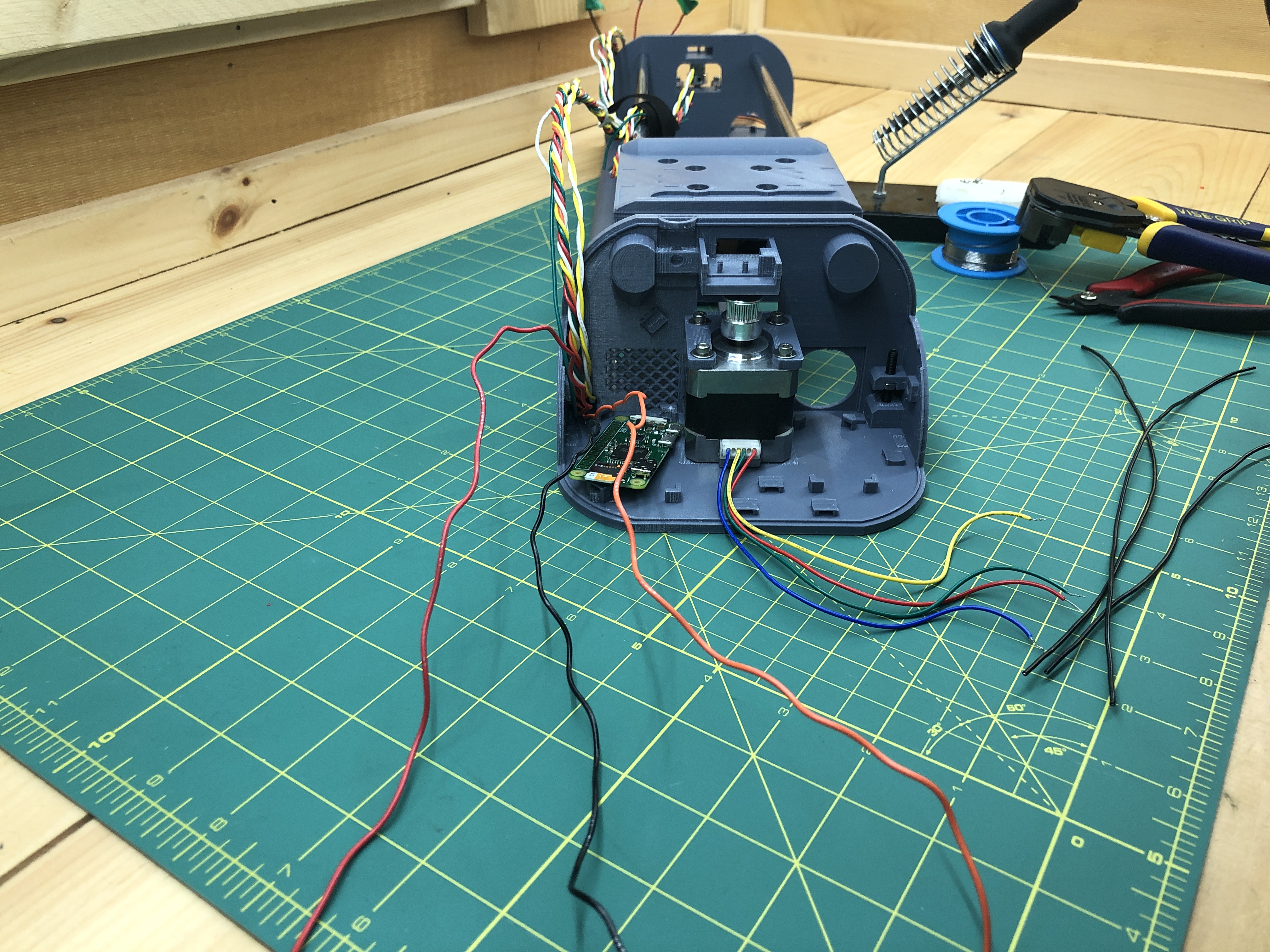
Grab 3 new black wires long enough to reach within the bottom terminal plus some slack.
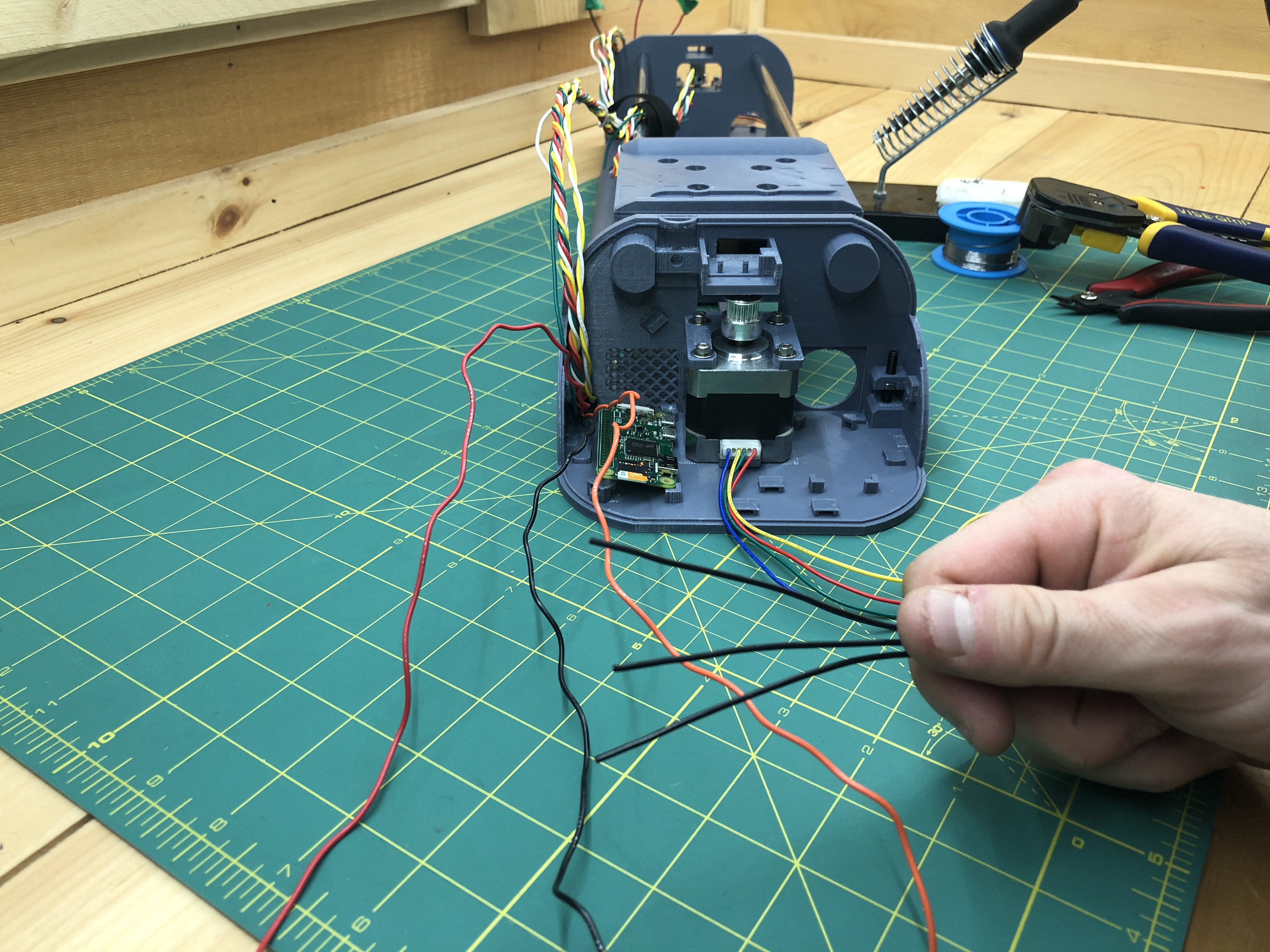
Strip them, we’ll connect them to the black wire from the red/orange/black power bundle. We want to split the black wire from the bundle into 3 for various components needing ground. You will most likely need to shorten the black wire from the bundle as it exits the “umbilical” from one terminal to the other.
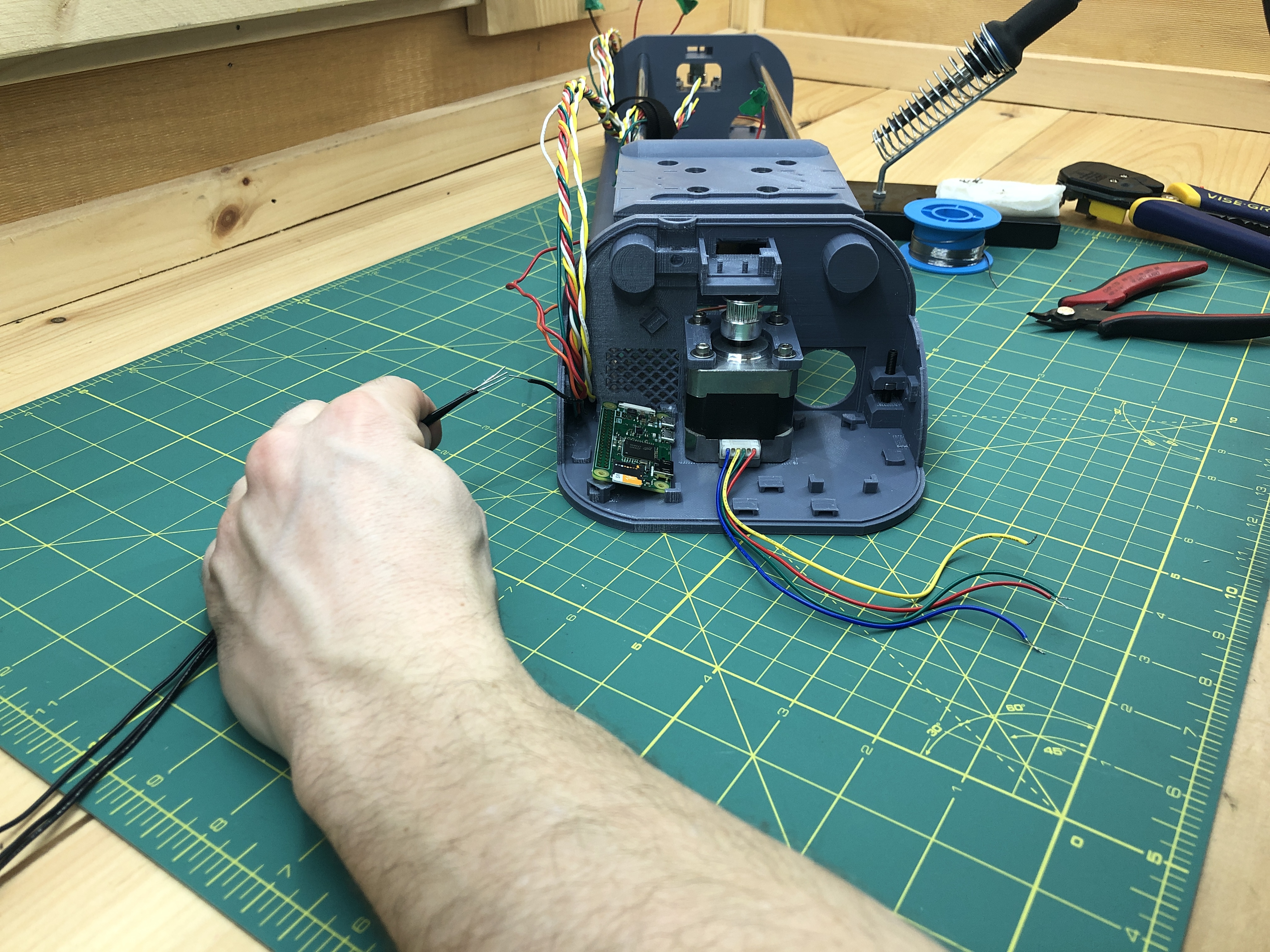
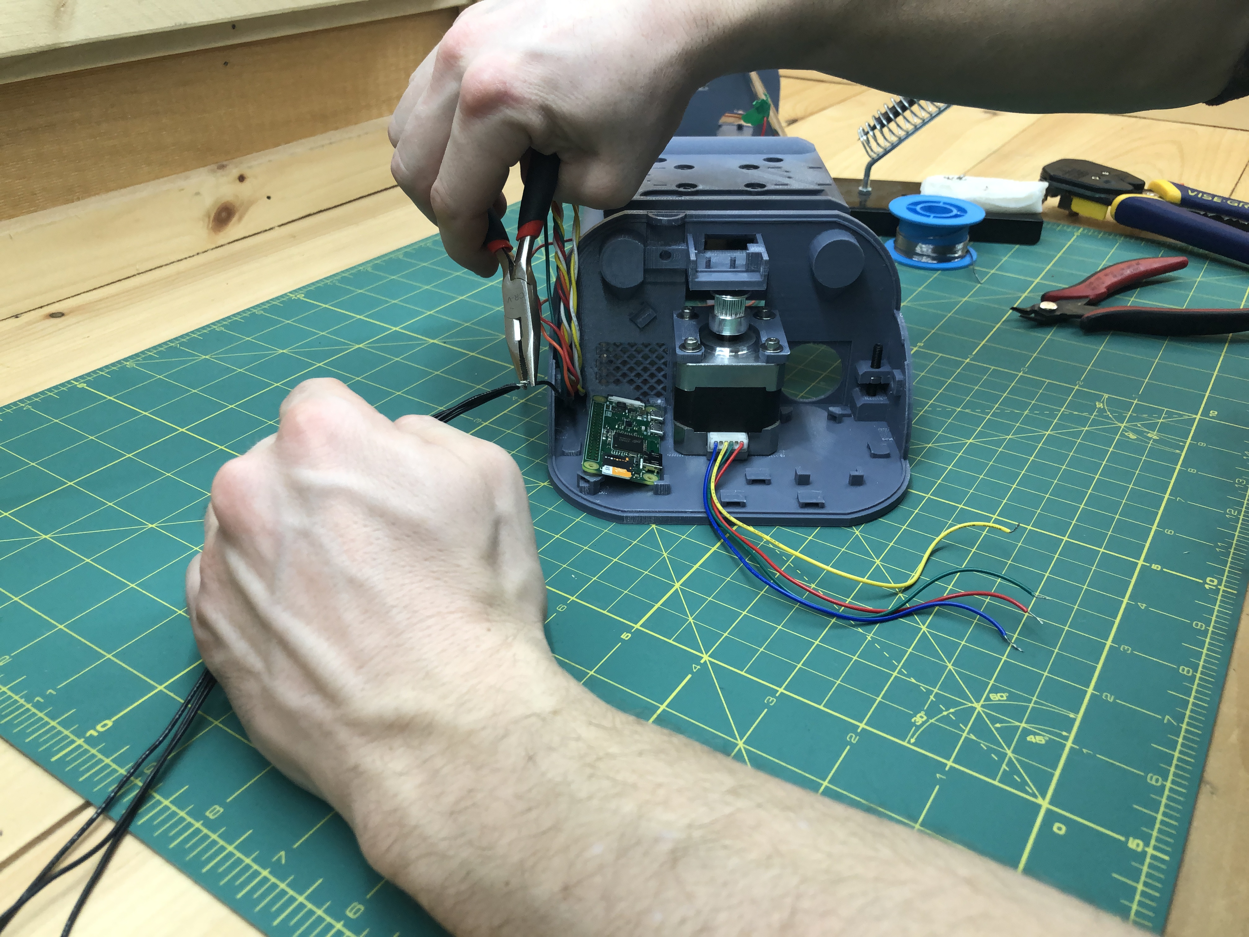
Let’s solder all this so it’s nice and sturdy (notice the heat shrink tubing we’ll slide over the exposed wire later).
Then we slide the heat shrink tubing over the expose area and shrink it with heat. I use heat from the soldering iron getting it close without touching, but if you have a heat gun it’ll work better and faster. Our ground is now 3 grounds.
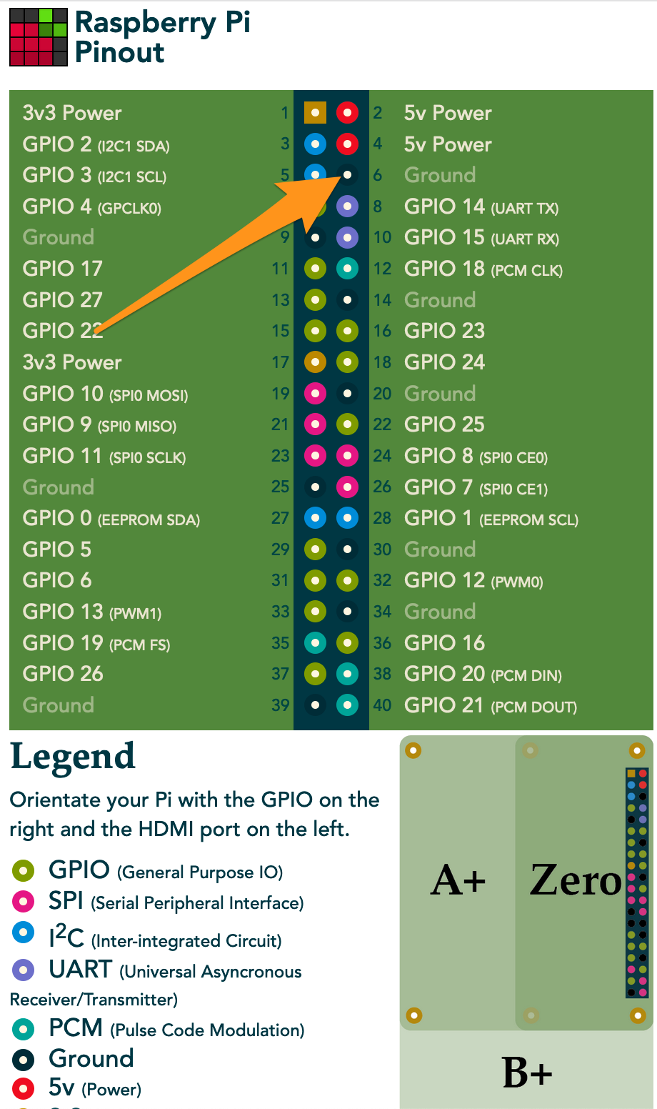
We’re about to start soldering onto the Pi. If you went with dupont connectors it’s pretty forgiving. However with soldering you want to make sure you hit the right pins. I use https://pinout.xyz as reference for Pi pins.
Solder one of the black wires you just attached to Pin #6 (Ground) of your Pi.
When soldering on the Pi (or anything really), you want to make sure you don’t create contact between pins.
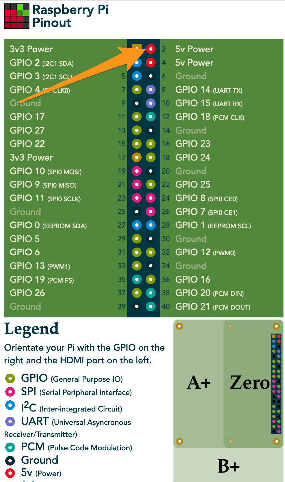
Now let’s solder the orange wire from the red/orange/black power bundle to pin #2 (5V power) of the Pi. Again, you may need to shorten it from the umbilical. In the power bundle, red is 12V, orange 5V, and black ground.
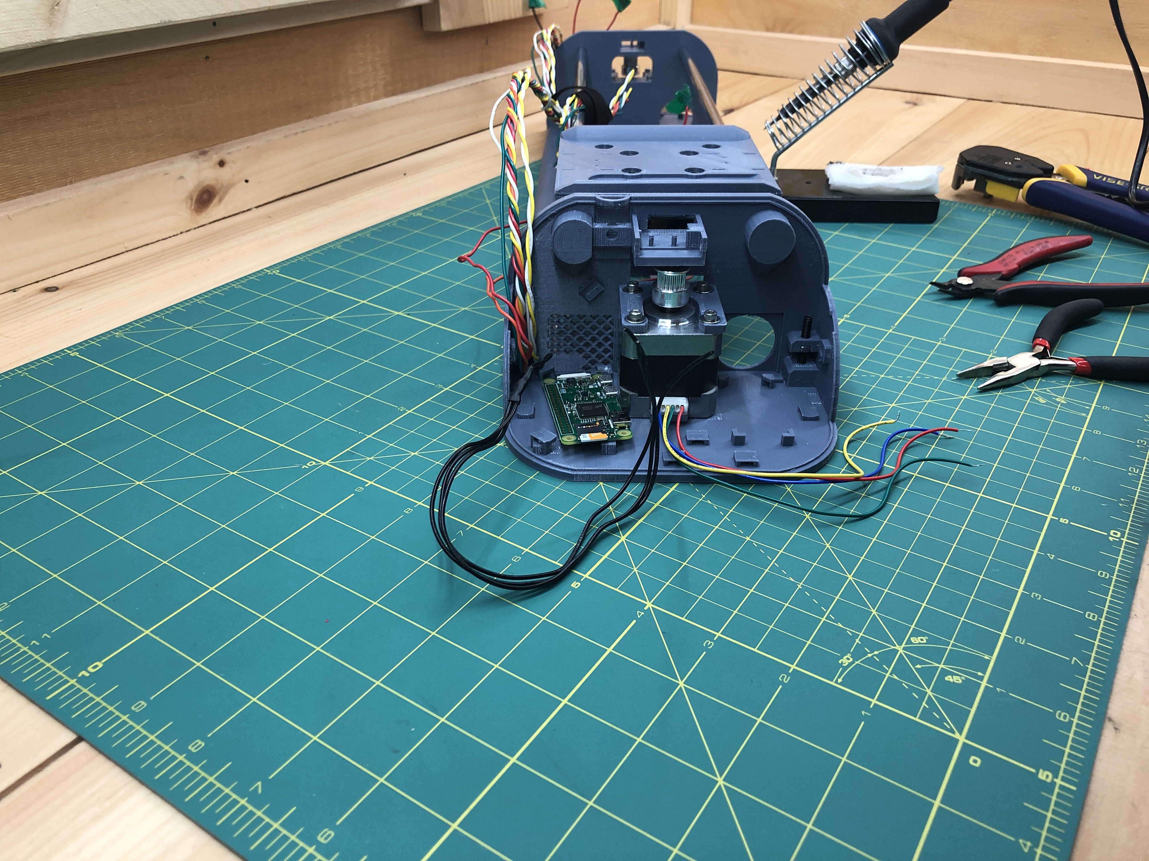
You now have power from your plotter to your Pi.
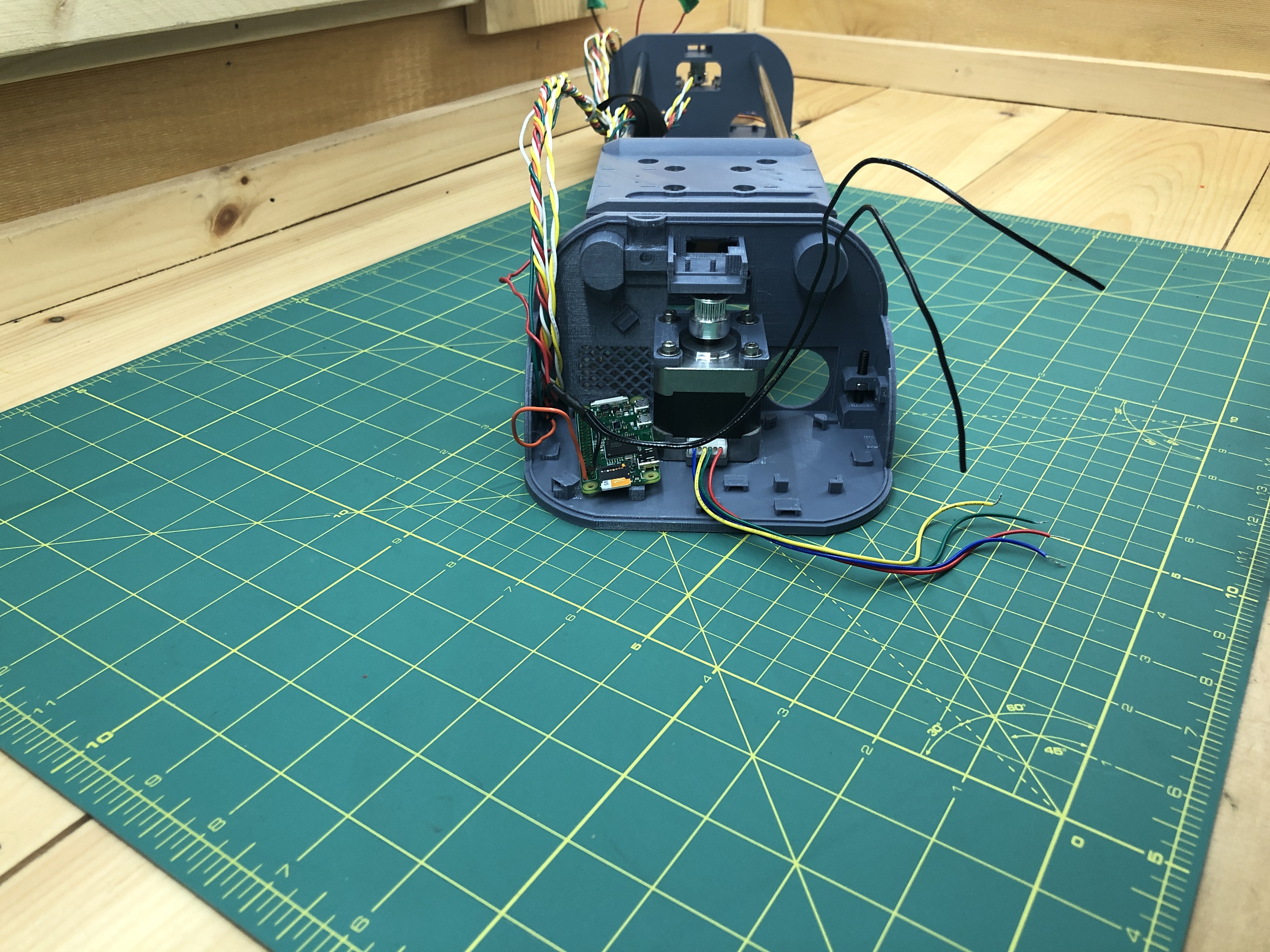
Make sure that the wires have just enough slack in them to allow for the Pi to rest in its final position.
Let’s power the plotter and make sure that the Pi is itself powered. Again we know this when we see a PlottyBot WiFi network. This second boot should be much faster, maybe a minute or two.
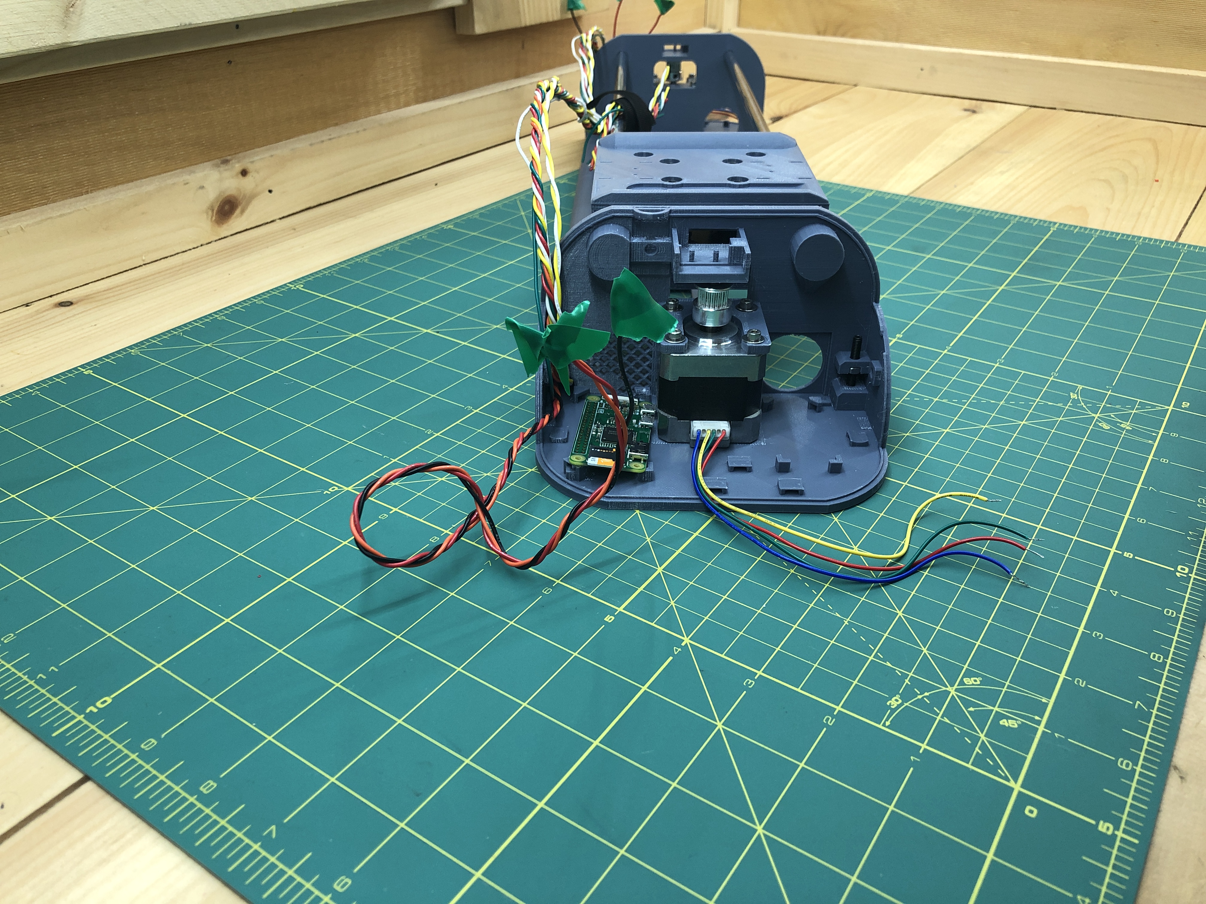
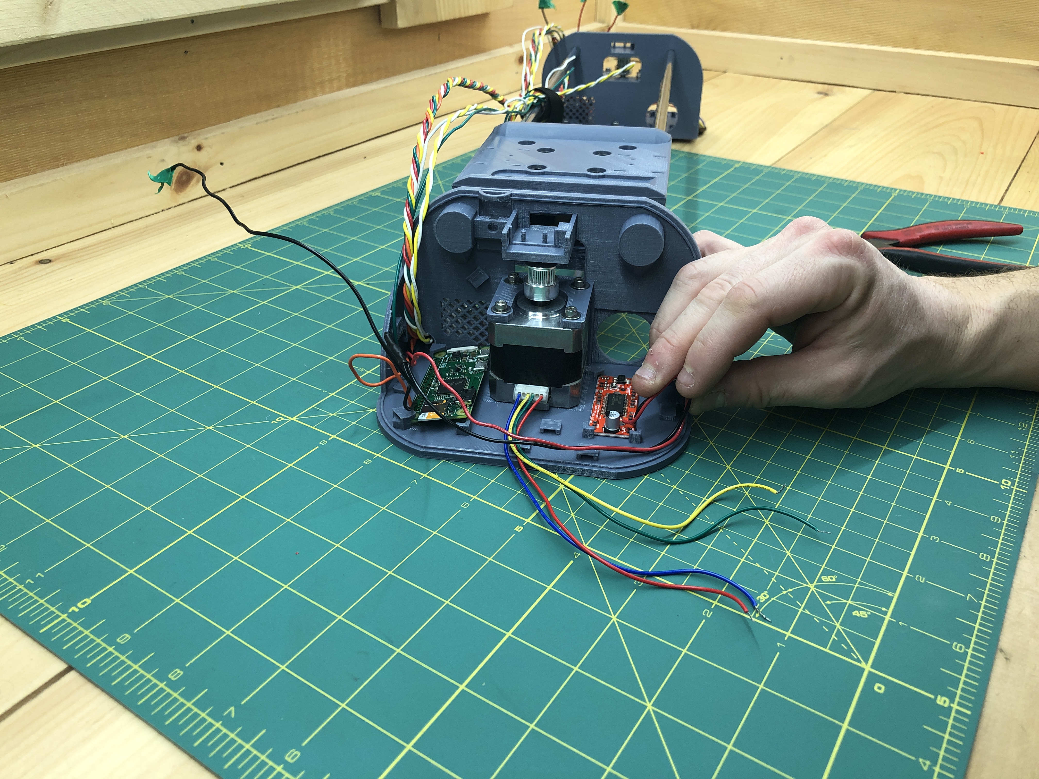
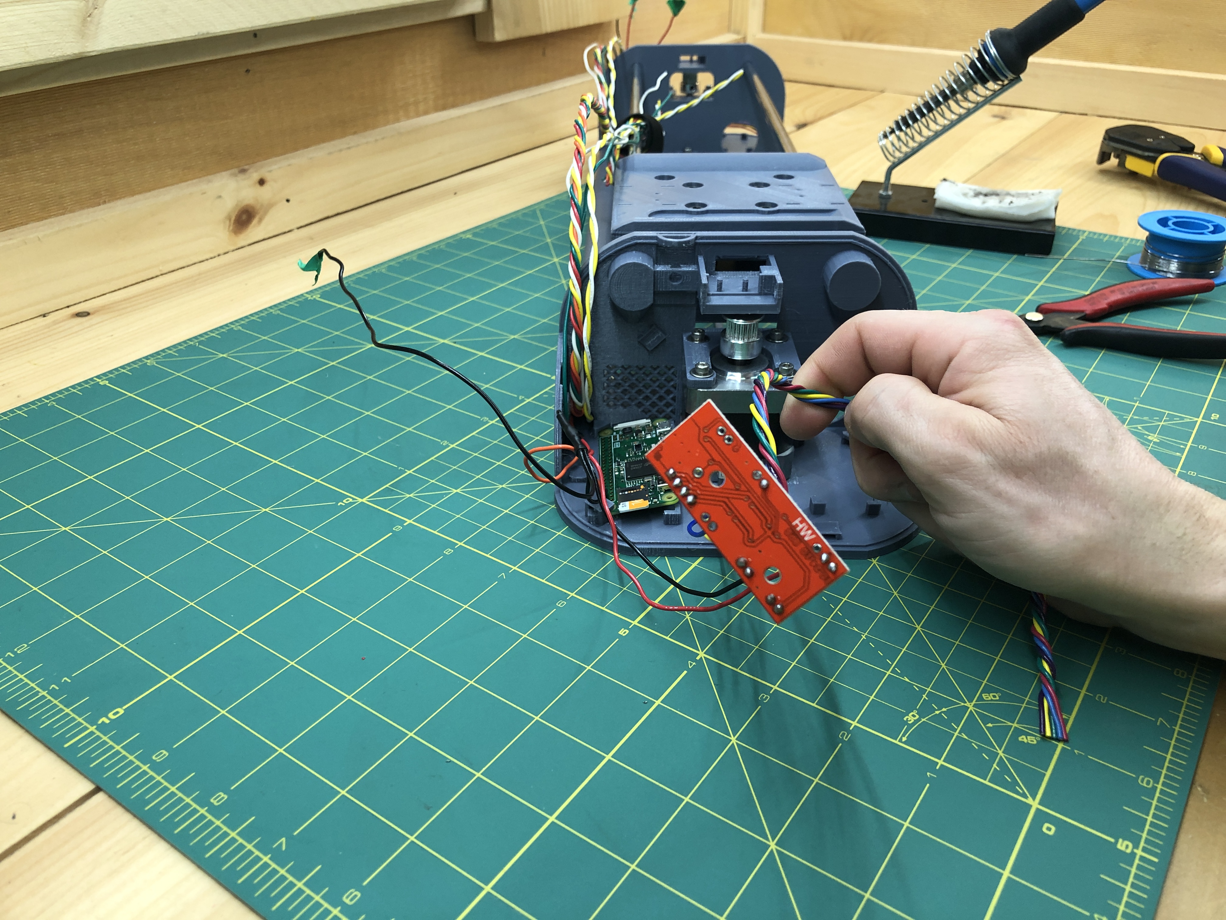
You see the PlottyBot WiFi network? Congratulations, you’ve just powered your Pi with your own power circuit. Let’s get to wiring the first stepper motor driver, the one in the bottom terminal next to the Pi. It goes in the holder on the other side. We’ll first connect power from our red/orange/black bundle. The driver takes 12V (the only red wire) and a ground (one of the 3 black wires you added). They go to the PWR IN + pin and the PWR IN GND pin on the driver respectively.
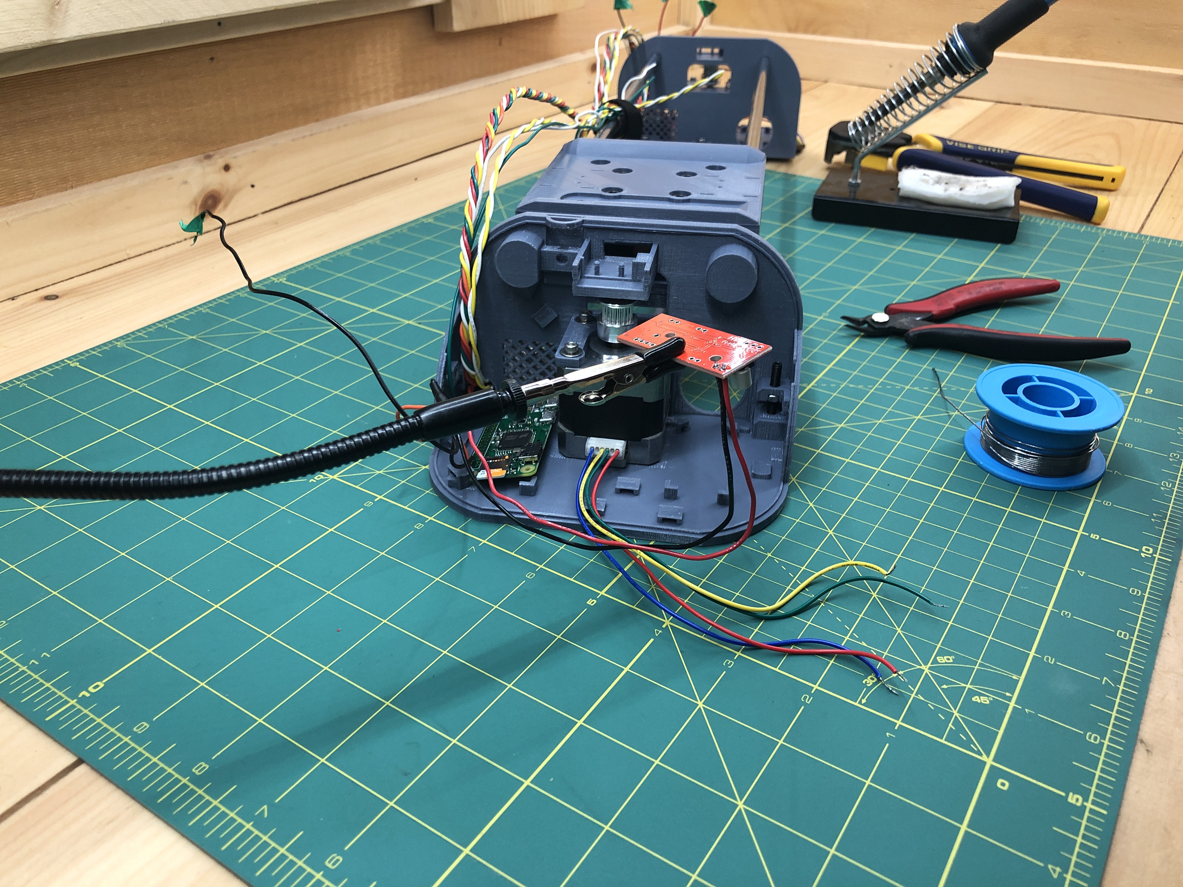
If you solder your connections, make sure that there isn’t too much wire sticking out beyond the solder blob.
The stepper motor driver’s got power.
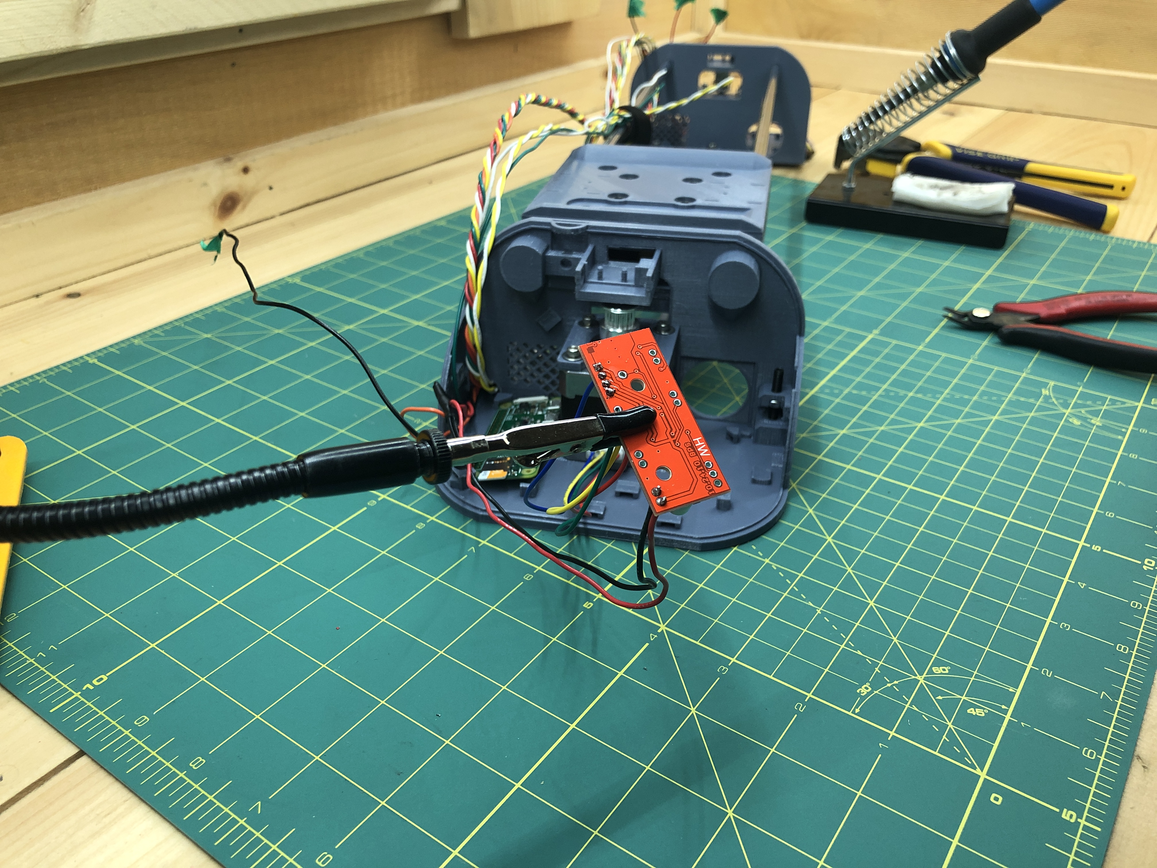
We’ll now connect the motor itself to the driver. I’ll be a bit more expedient with the pictures by showing only the results. You can always refer to the full circuit to know which stepper motor wire goes to which pin on the driver and I recommend you do so. Essentially the other is blue/yellow/green/red going from coil A to B.
Now grab 5 wires of various colors (except black and red).
Twist them into a bundle that can reach within the terminal (plus some slack).

Connect one end of the bundle to the driver pins, we will use ENABLE, DIR, STEP, MS1 & M2. Again, the full circuit comes in handy.
Place the driver loosely in its holder.
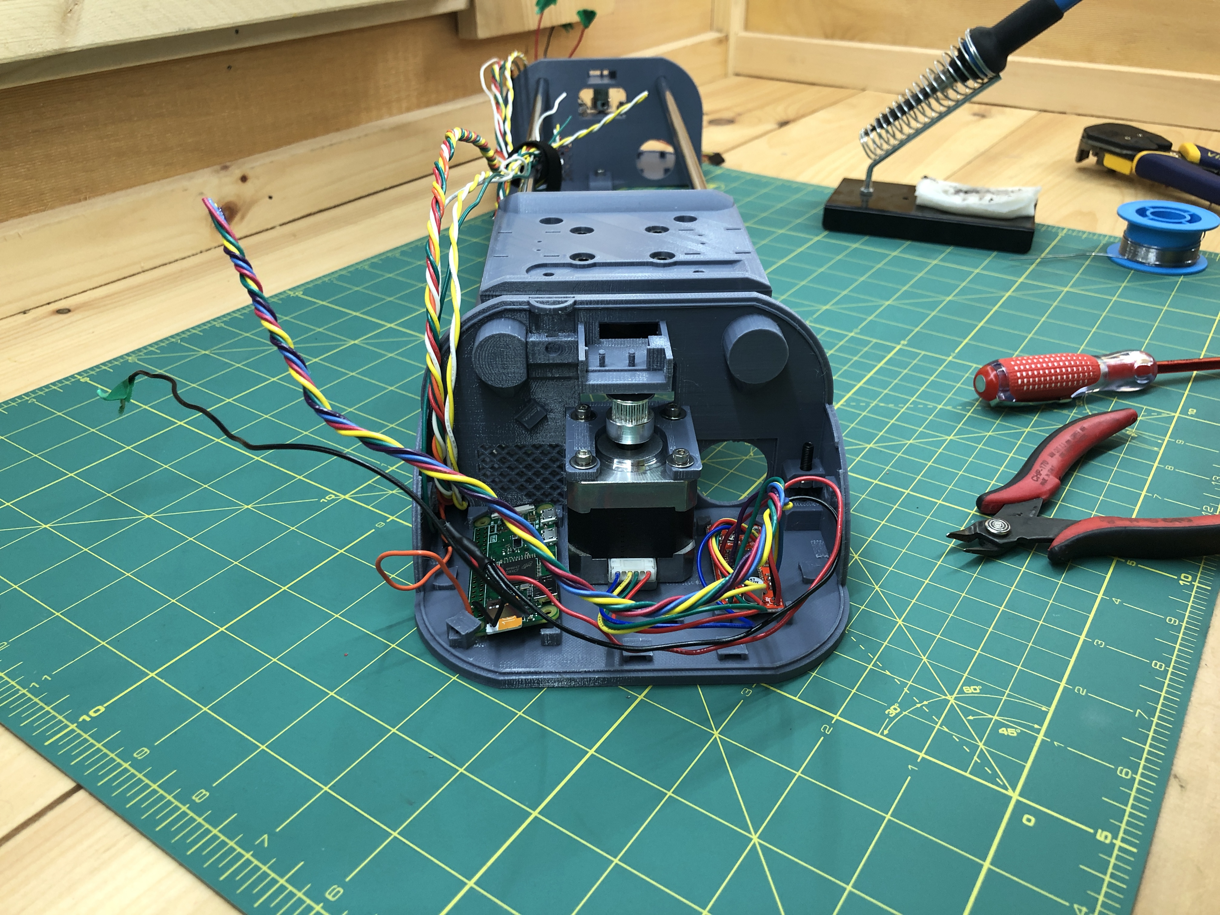
Now we’ll connect our new twisted bundle to the Pi. Wires will be a little crazy as we move on with more components. Always make sure they can reach to where they need to go, and be ok with components “floating in the air” supported by wires you connected. Of course, if you are using dupont connectors, you can simply have components sitting in their holders and connect them as needed. The only trick is to create wires of appropriate length. The full circuit will tell you which wire of your bundle goes to which pin of you Pi.
To confirm:
Pi pin #37 (GPIO 26) goes to driver ENABLE
Pi pin #35 (GPIO 19) goes to driver STEP
Pi pin #33 (GPIO 13) goes to driver DIR
Pi pin #31 (GPIO 6) goes to driver MS1
Pi pin #29 (GPIO 5) goes to driver MS2
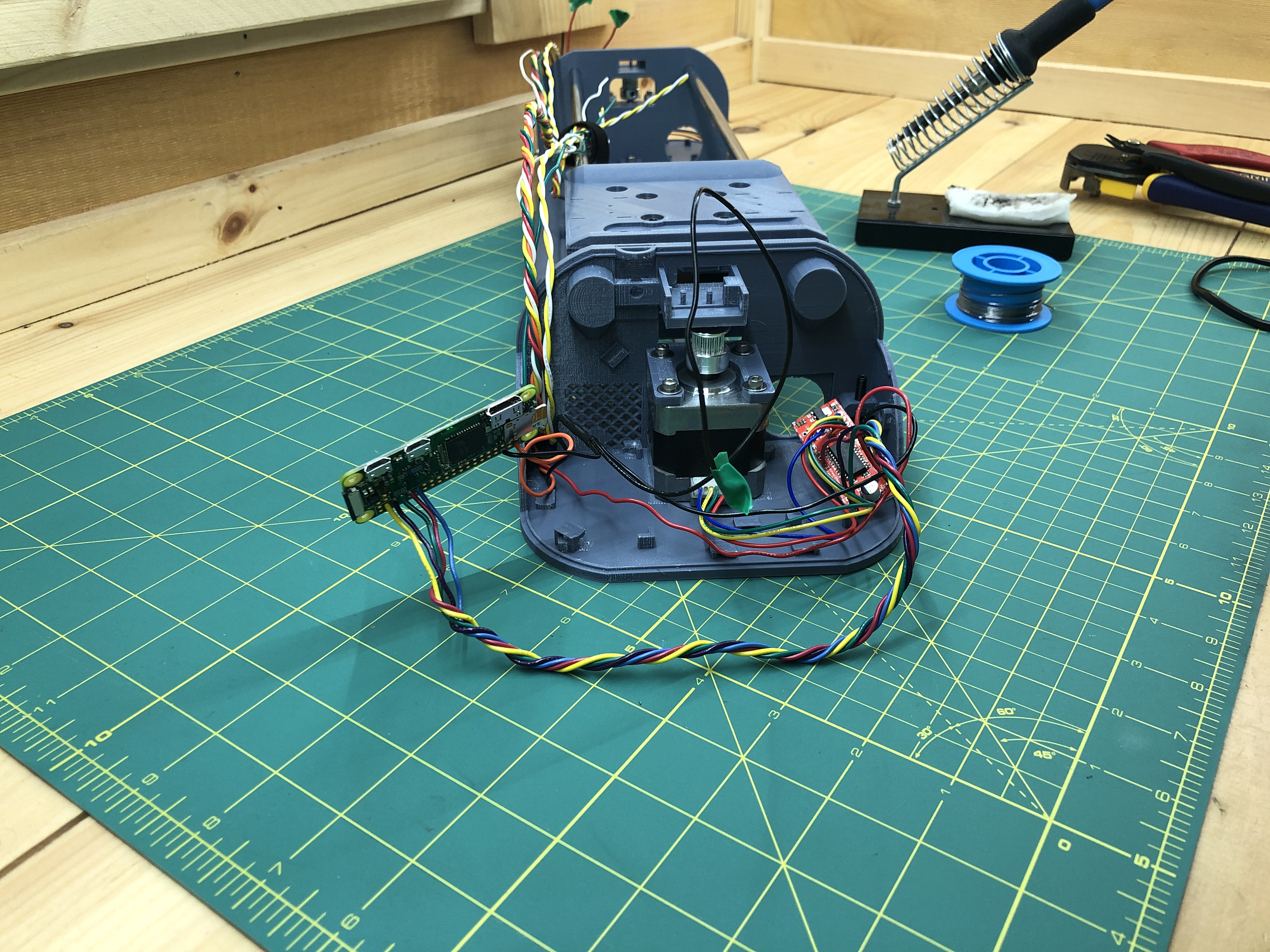
When all the driver wires are connected, let’s power the plotter once more. Connect to the PlottyBot WiFi network, point your browser to http://plottybot.local and let’s see if the bottom stepper will move.
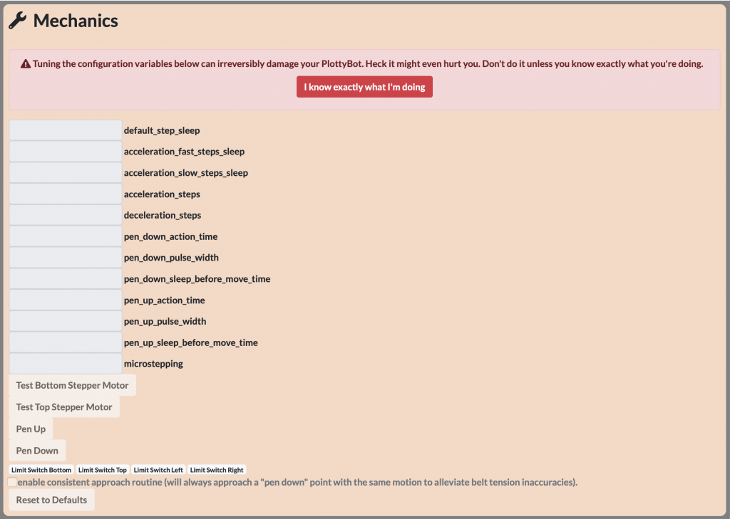
Scroll down to the “Mechanics” section of the web interface. This section is only enabled if you know what you’re doing.
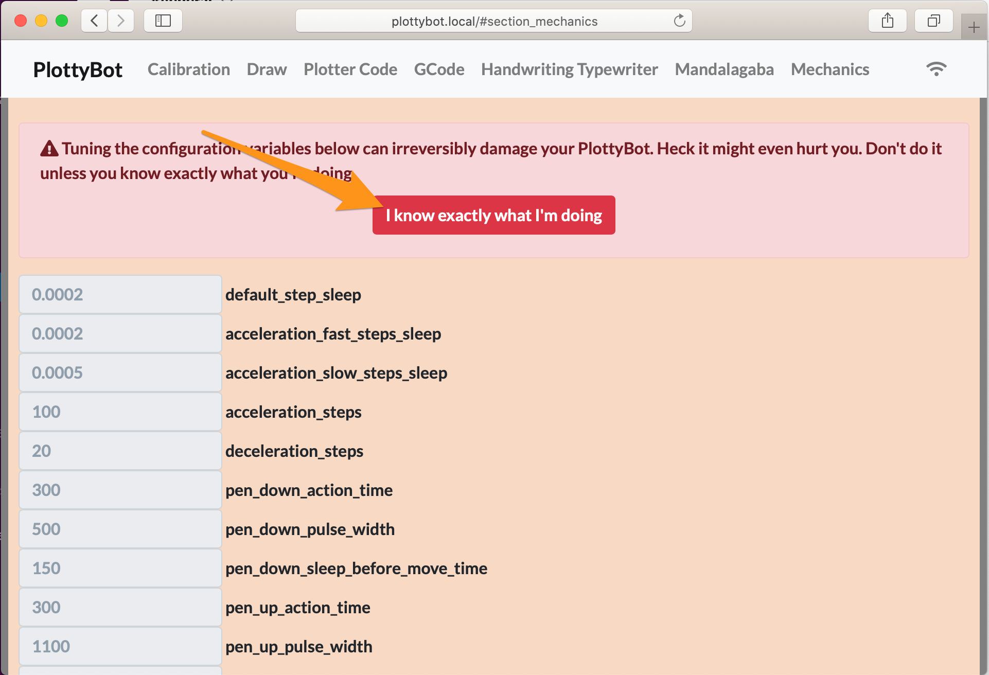
Click on “Test Bottom Stepper Motor”.
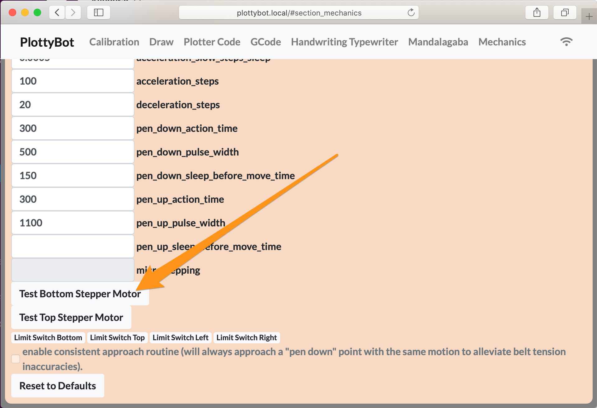
Your bottom stepper should move back and forth 4 times with a different sound pitch every time. What’s going on is that it’s instructed to rotate a certain amount at various levels of microstepping. If you don’t see this behavior, one of the wires from the Pi to the driver is misconnected, or the driver is bad. Remedies are case by case and will trying various scenarios to isolate the issue. Drop a comment if you’re stuck.
Let’s now wire up the top terminal’s stepper motor. Remember how we bundled 5 wires going from the terminal where the Pi resides (bottom) to the terminal where the power resides (top)? Well this bundle is meant for the top terminal stepper driver.

Going quick because we’ve already done this on the other side. Grab a red wire and a black wire from the power outlet and connect them to the stepper driver’s PWR IN + and PWR IN GND pins as you’ve done on the other terminal. Also connect the terminal’s stepper motor coils as you have done before. And finally, connect the 5 wire bundle to it. On the other side of the plotter, this 5 wire bundle goes to the Pi and will join:
Pi pin #40 (GPIO 21) goes to driver ENABLE
Pi pin #38 (GPIO 20) goes to driver STEP
Pi pin #36 (GPIO 16) goes to driver DIR
Pi pin #32 (GPIO 12) goes to driver MS1
Pi pin #28 (GPIO 1) goes to driver MS2
On the other side of the plotter:
Power the plotter once more, connect to wifi, go to the web interface and into the “Mechanics” section. Click the “Test Top Stepper Motor” button this time.
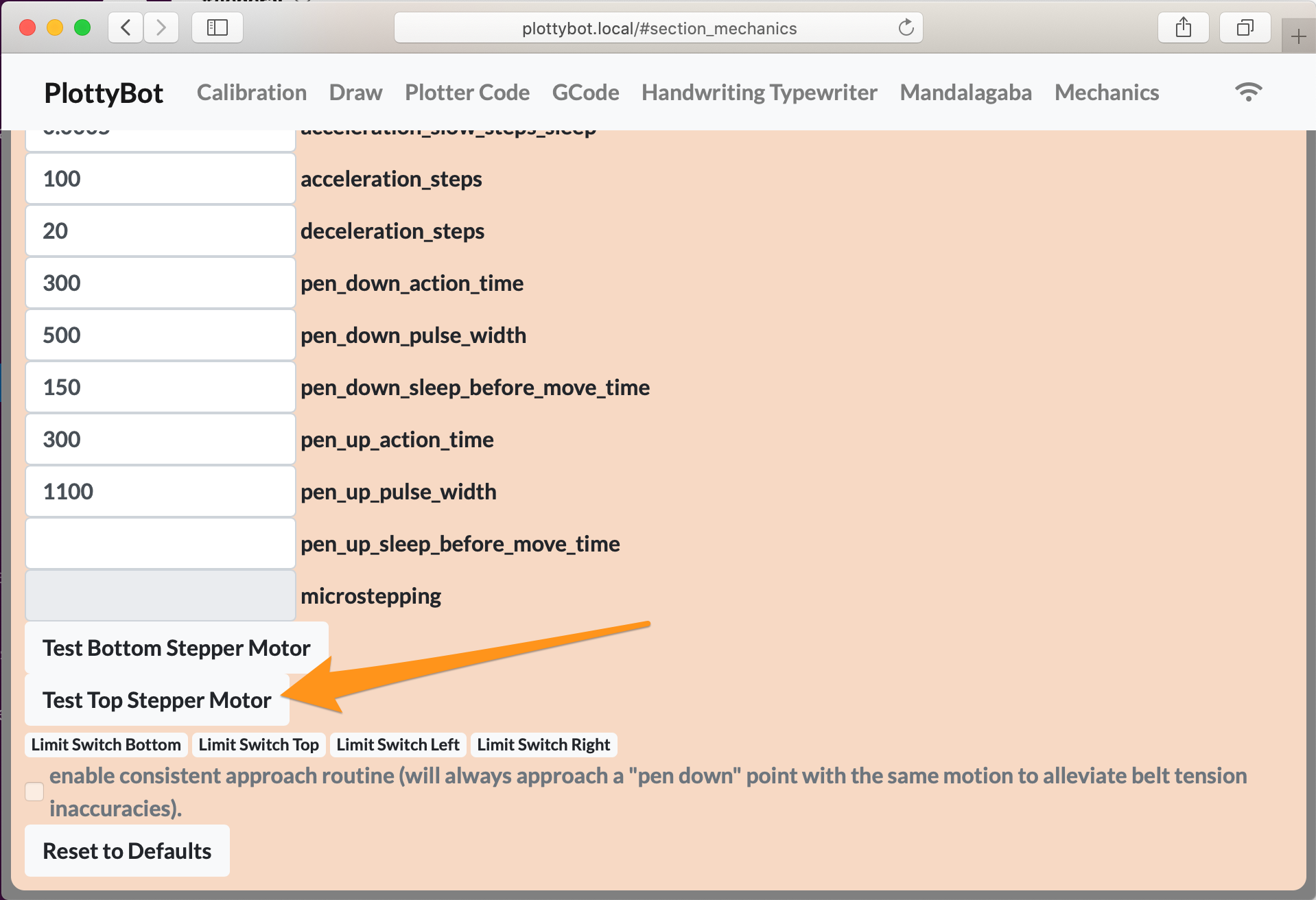
Once again you’ll see the motor move 4 times the same way, but with various sounds.
Once again if you don’t, you’ll want to investigate and isolate the issue.
7. Fans
Electrical:
2 fan
The fans are wired in series and not tied to the Pi, they just spin when the plotter is powered.
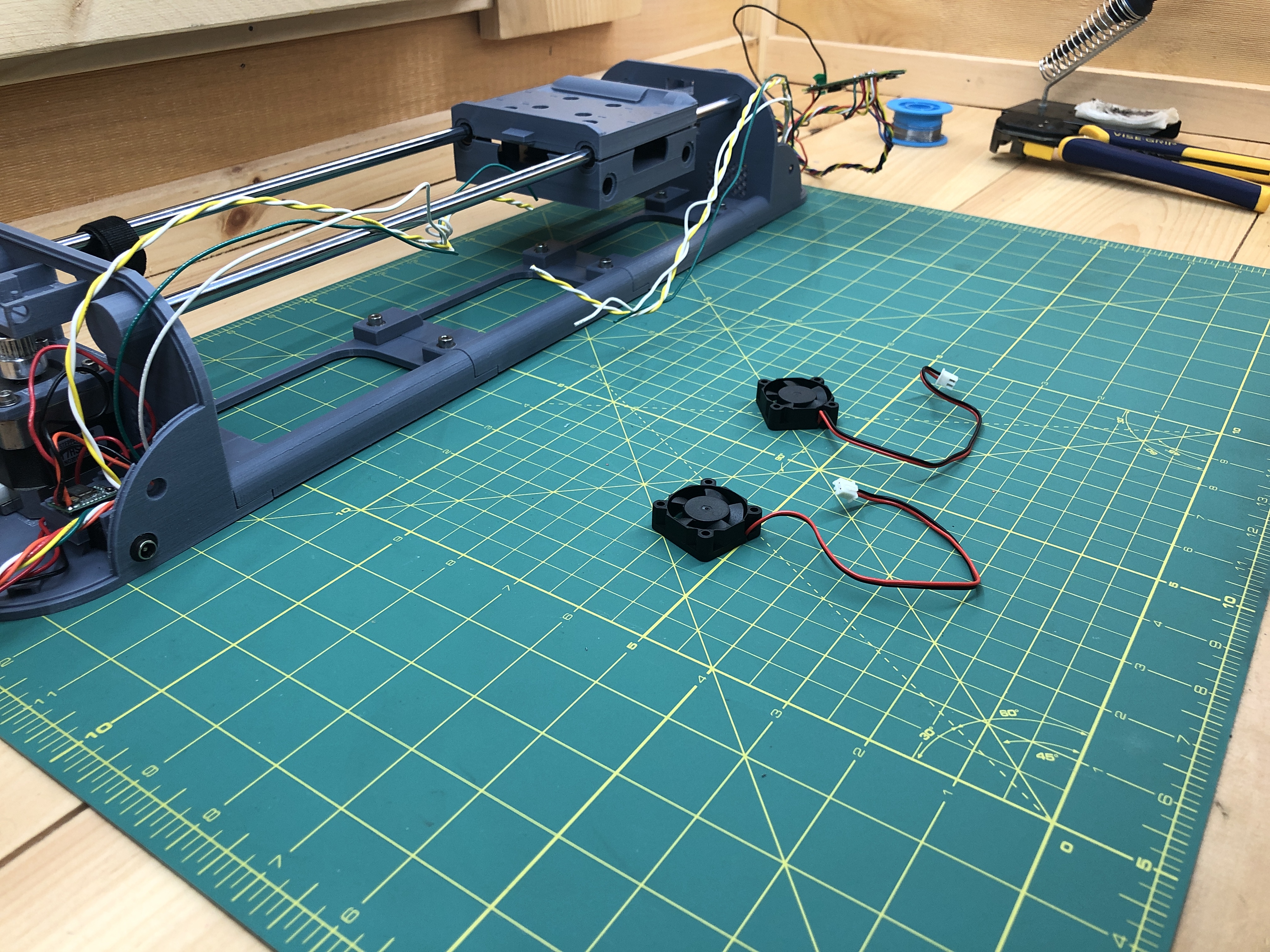
Start with the top terminal (where power is), the fan will pressure fit in the driver corner. The stepper driver can get hot which is why we give give it good airflow, we’ll also give it heat sinks later on. These fans have a slightly different width and height so make sure it goes in at the right orientation. You can then connect a red wire from the red/orange/black power bundle. Do not however connect the black side, because they are wired in series, we’ll instead use one of the standalone wire we have in the umbilical.
Then with heat shrink tube.
On the other side of the plotter (bottom), we connect the standalone wire from the umbilical to the red (positive) wire of the other fan. Its black (ground) side goes to one of the power bundle’s black wire. Again, the fans are connected in series.
Now with heat shrink tubes.

You can power the plotter again to make sure both fans are spinning.
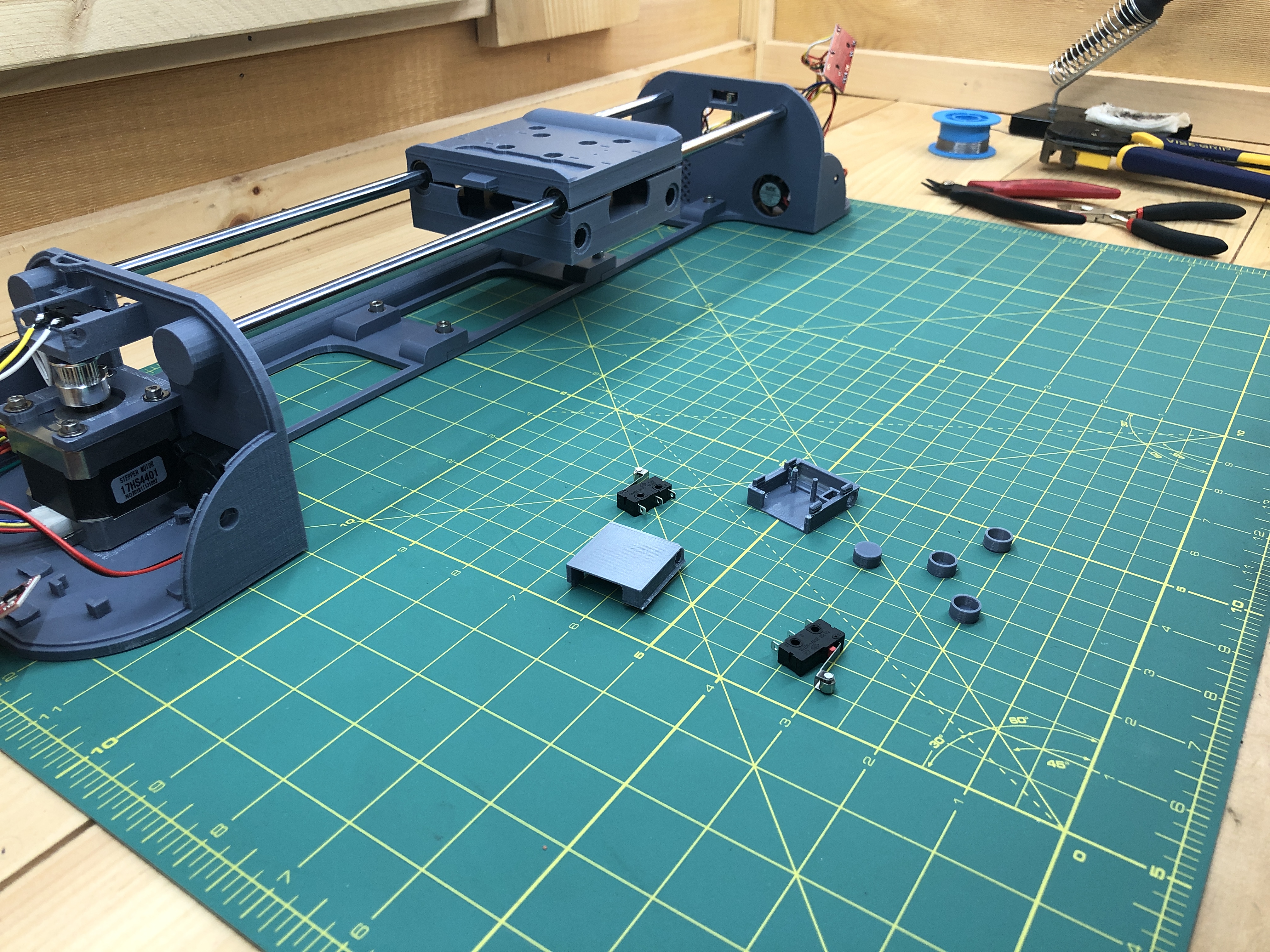
8. Limit Switches
Hardware:
1 M4x8 hex screw
1 M4 nut
2 M4x40 hex screw
2 M4x35 hex screw
4 M4 lock nuts
8 washers
3D printed:
gondola_top_screw_cover_x4
gondola_top_limit_switch_cap_x2
gondola_top_cable_management_x1
Electrical:
4 limit switch
wires
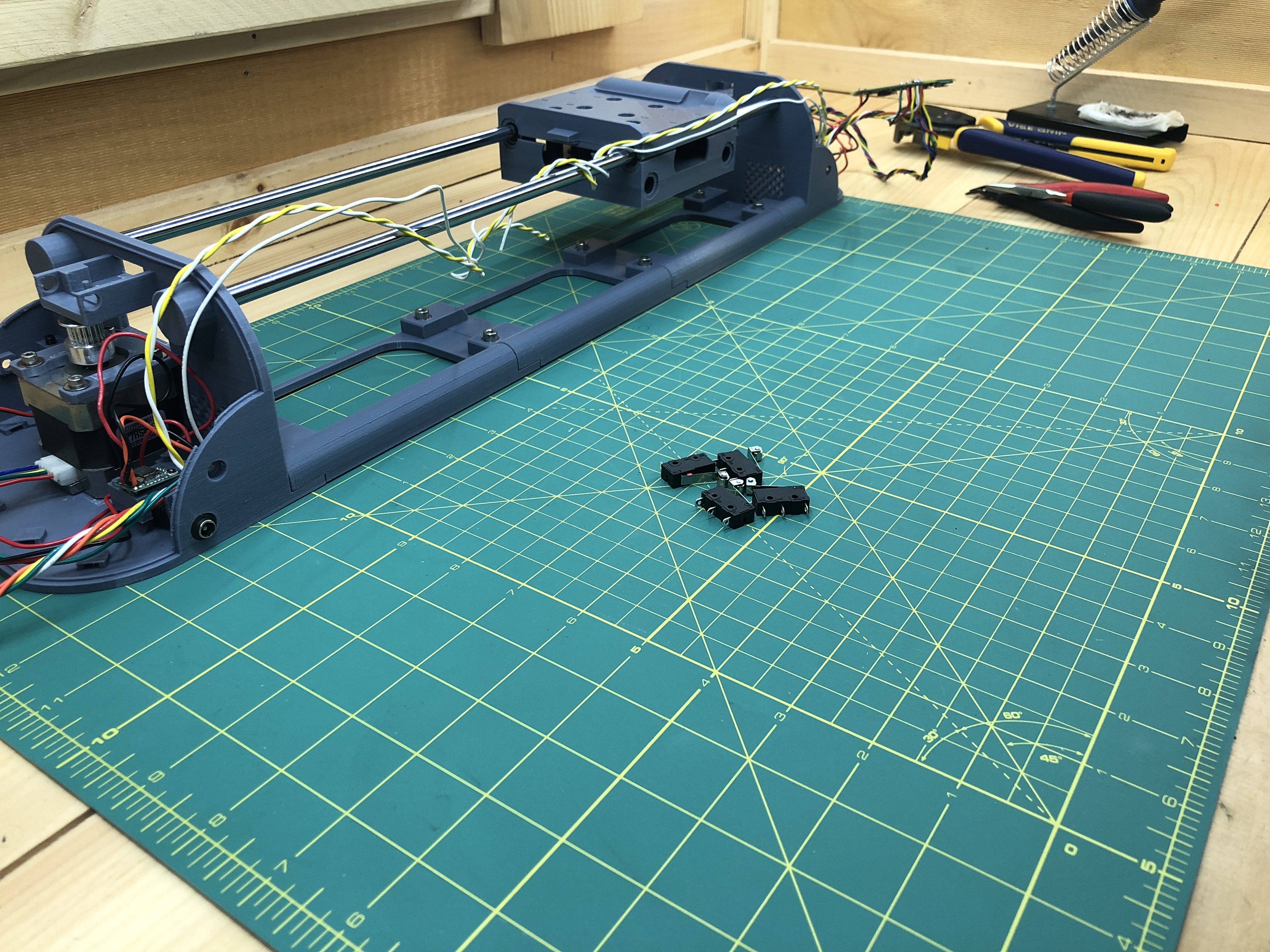
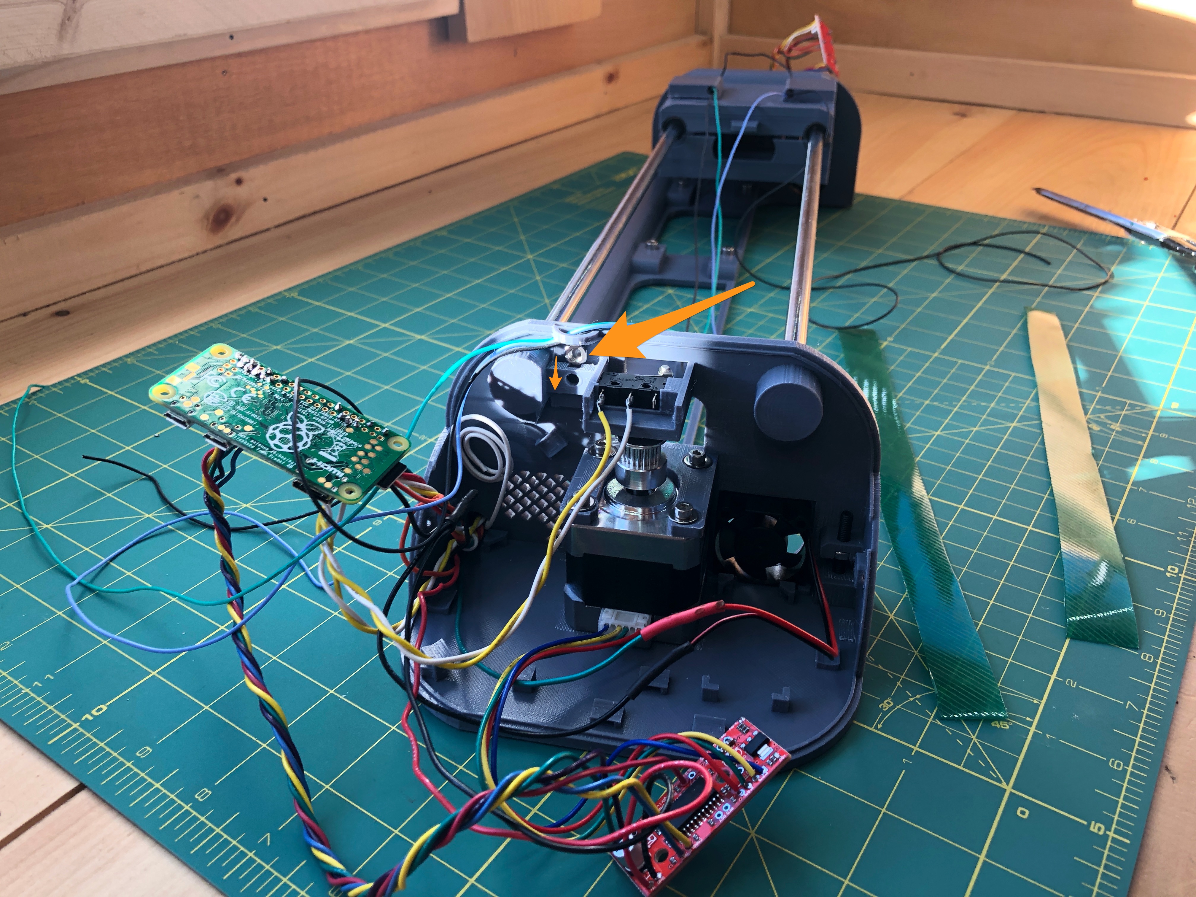
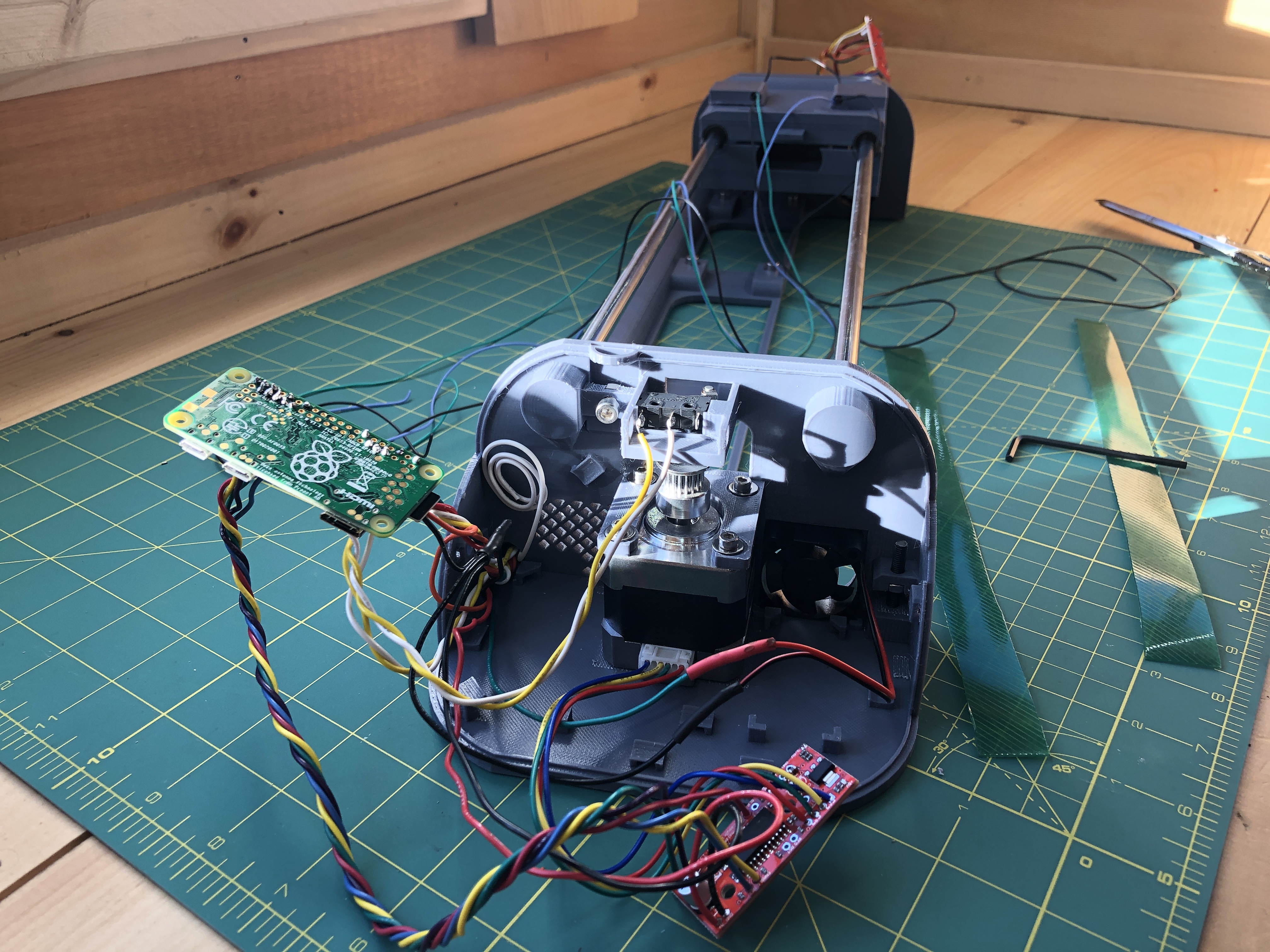
At the top terminal, put a limit switch in its enclosure. Run the yellow/white bundle from the umbilical to it and cut it to length (plus some slack just in case). Strip the wires and attach white to the middle pin, and yellow to the pin on the side where the little red button is.
Solder the wires in place, this is valid also if you use dupont connectors, this will help a lot.
Put the switch back in its holder.
At the other terminal (bottom), grab a limit switch an solder a new twisted pair of yellow/white wires, long enough to reach within the terminal.
Solder both the yellow/white pair from the umbilical, and the new yellow white pair you created into the Pi. In both cases, white will go to a ground on the Pi, you can pick any 2 grounds from the Pi, find them using https://pinout.xyz. For yellow, the switch from the top terminal going through the umbilical should be connected to Pi pin #11 (GPIO 17), while the switch from the bottom terminal should be connected to Pi pin #7 (GPIO 4).
Again components will be floating not in their holders, but you want to be mindful when wiring them up that they’ll be able to get back in there. This is less of an issue with removable dupont connectors where the component can rest in place and wires brought and connected to them directly on the top. With soldering we need to flip the components over so we can solder their bottom side, it’s definitely messier to work with.
You’ll notice you’re left with 1 cable on its own in the umbilical. It serves no purpose :). It’s meant as a backup in case another is faulty, if we mess one up, or for potential future expansions. Now that, is what I call planning ahead. For now we can simply coil it up to prepare it for storage.
With this last wire out of the way, we can slide the gondola to both extremities and make sure it triggers the 2 limit switches (you’ll hear a distinct “click” when it does). You want to gondola to trigger the limit switch before it runs into the terminal, with a bit of room in between to be safe. You can adjust the switch by bending it’s metal arm, do so until you’re satisfied with the location at which it triggers.
Let’s grab our 2 gondola_top_limit_switch_cap, our 4 gondola_top_screw_cover, and our remaining 2 limit switches. They’ll go on the top of the gondola.
They go in their caps like this:

We simply put the gondola_top_screw_cover on top of the gondola’s innermost hex screws. They’ll be held in place with the limit switch caps. They don’t serve any purpose 🙂 just here for aesthetics.
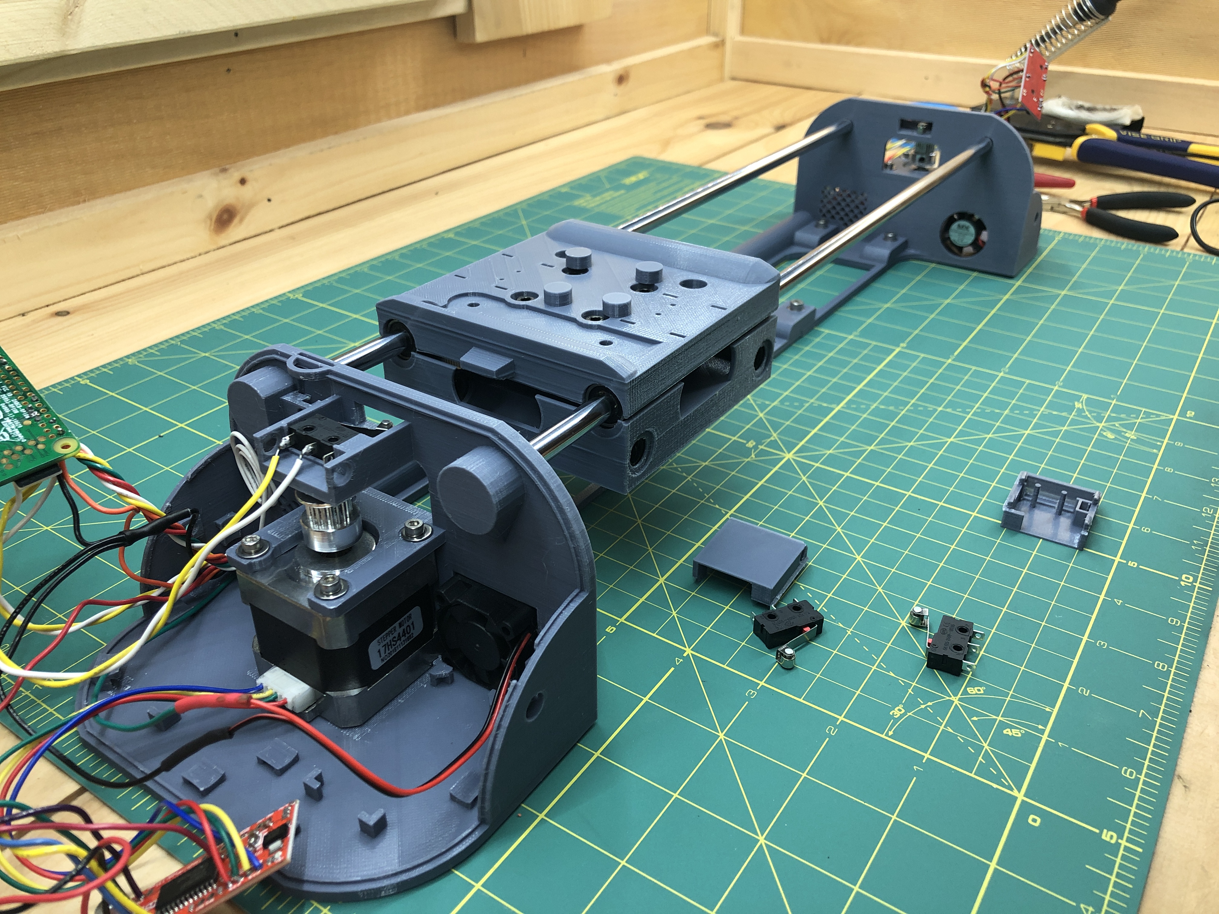
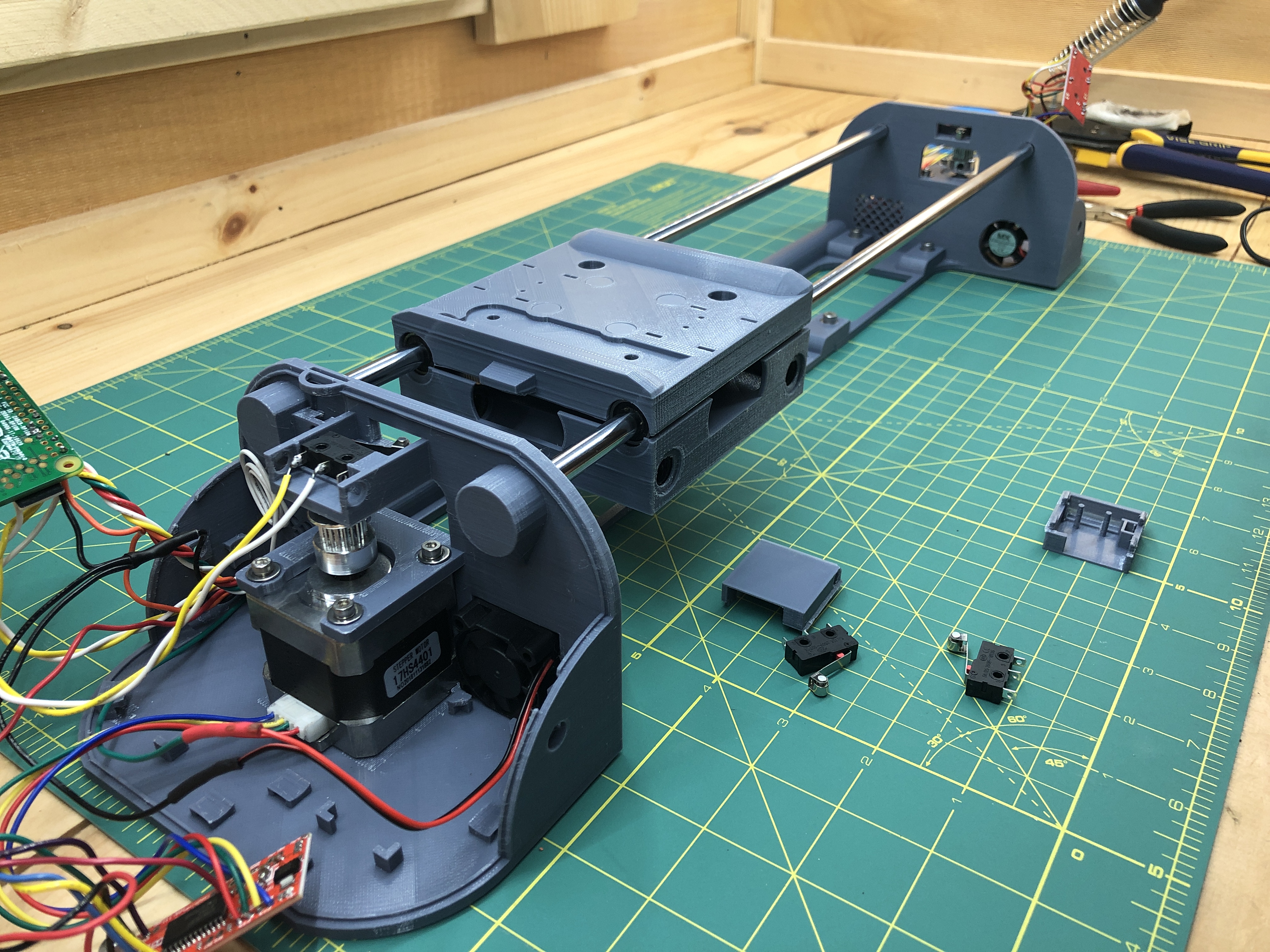
Now we’re going to wire the limit switches on our work surface, and then we’ll put them on the gondola. Wiring them is a bit tricky because you want their wires to go through their cover’s holes. But Also because they share a single ground which will go all the way back to the bottom terminal, and then extend all the way our the X axis, where the pen will go. Other than this ground, they also both have their own signal wire going back to the bottom terminal.
Here’s a schema of what we’re after, it include 2 other wires (yellow and red) which are just passing through the gondola on their way to the pen assembly. We are not worrying about these 2 right now, only black, green and blue.
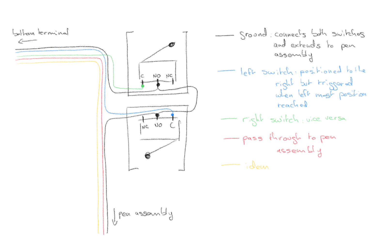
What my wiring looks like when it’s done:
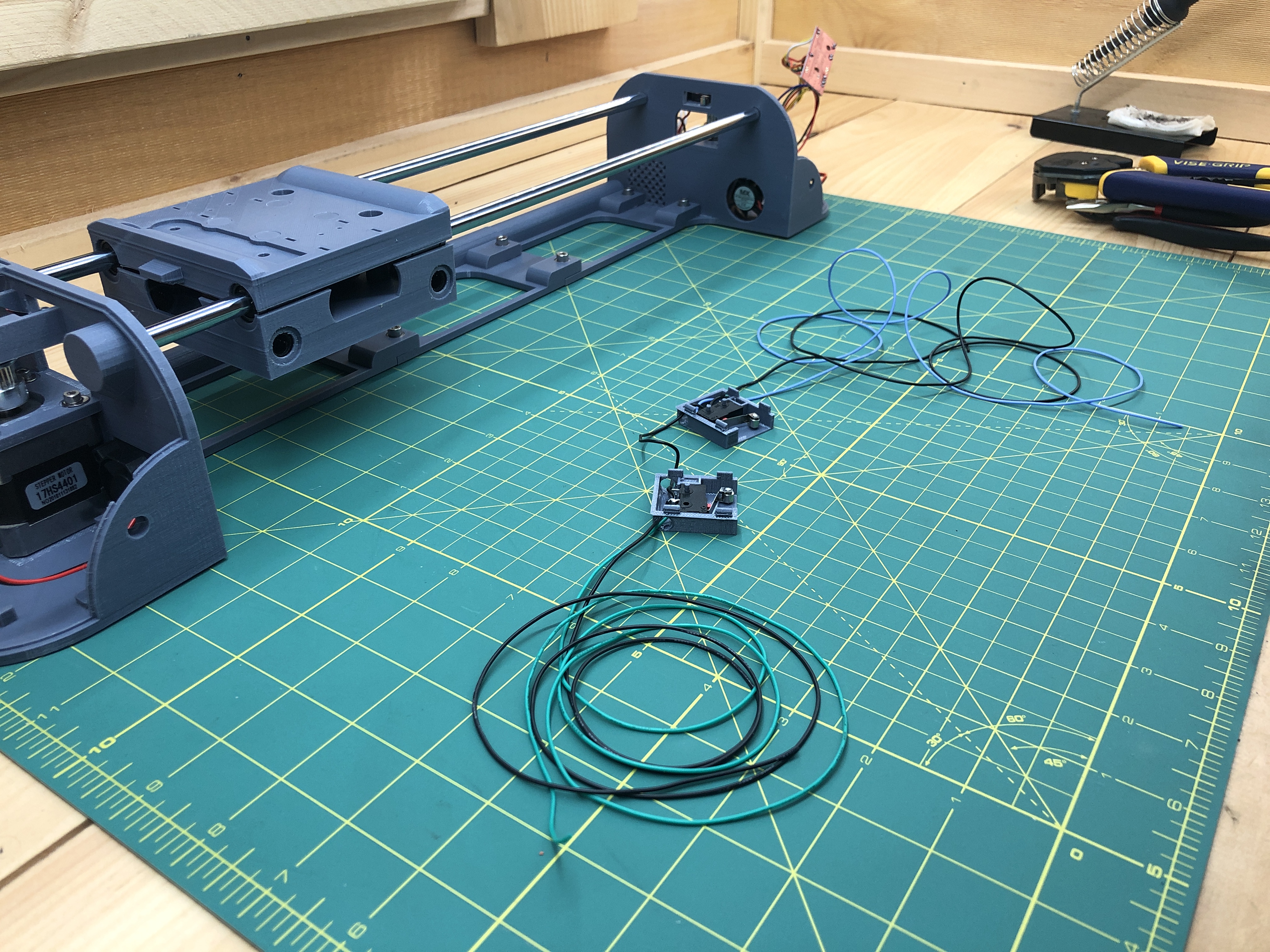
For the wires which go to the bottom terminal or the pen assembly, make sure they are plenty long enough plus some slack. We’ll cut then to size later.
You can then pressure fit the limit switch covers into the gondola. They’ll click into place but as we mentioned before, 3D printing isn’t always super accurate and so don’t hesitate to shave off plastic where fitting isn’t happening.
As you can see, the ground 2 limit switch signal wires go back to the bottom terminal while another ground is left dangling at the gondola.
Let’s now grab a piece of flexible plastic. Any plastic will do that can be cut with scissors and give rigidity and flexibility to carry the wires between the bottom terminal and the gondola. I found that a plastic folder that gives me exactly that and I’ve been using it since :). I’m sure there are tons of other options in one’s house.
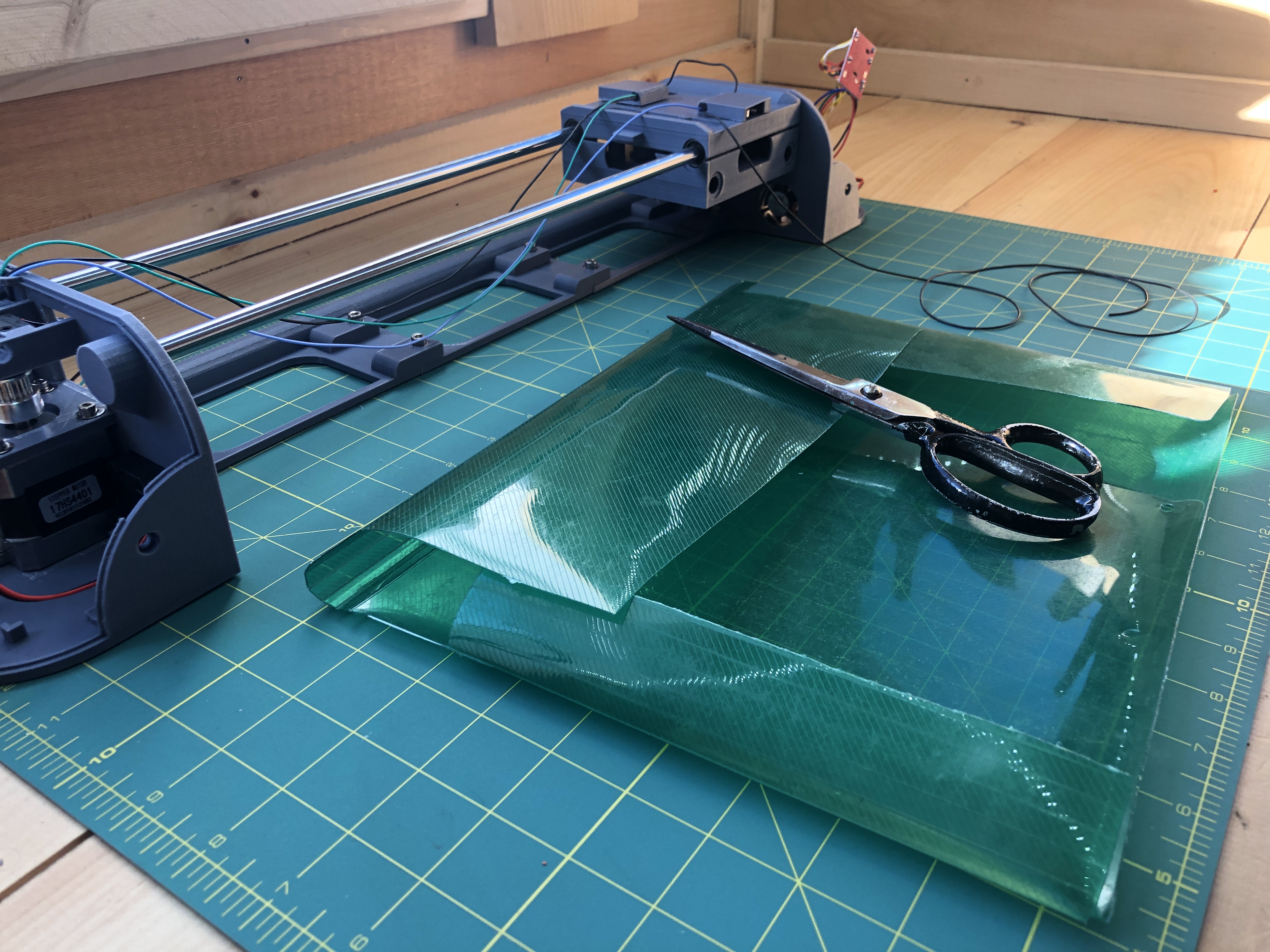
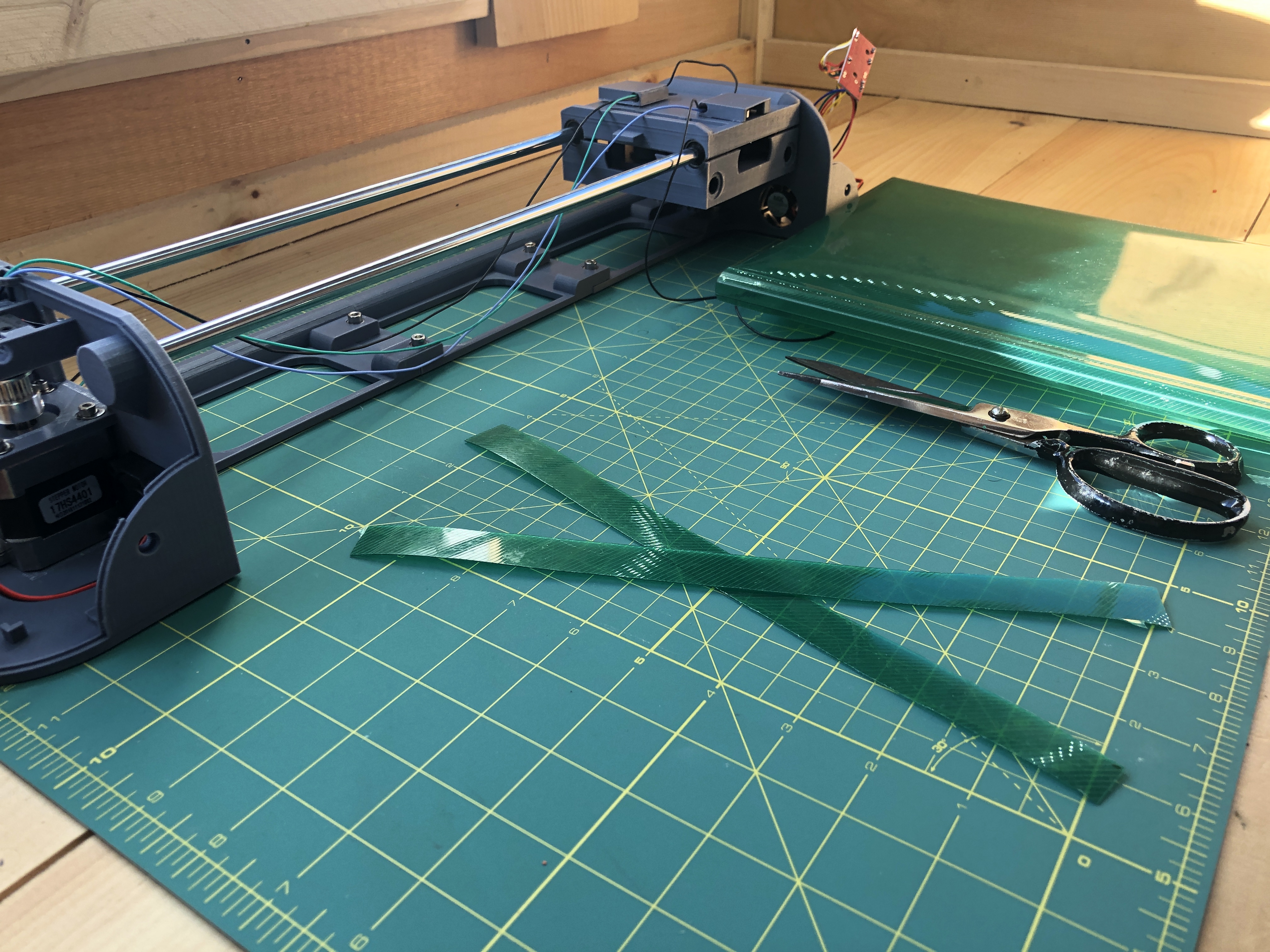
I’m cutting 2 pieces here because 1 doesn’t suffice to reach all the way across so I’ll join 2. You also will want another length to go on the X axis from the gondola to the pen assembly.
This is the sort of flexibility we want.
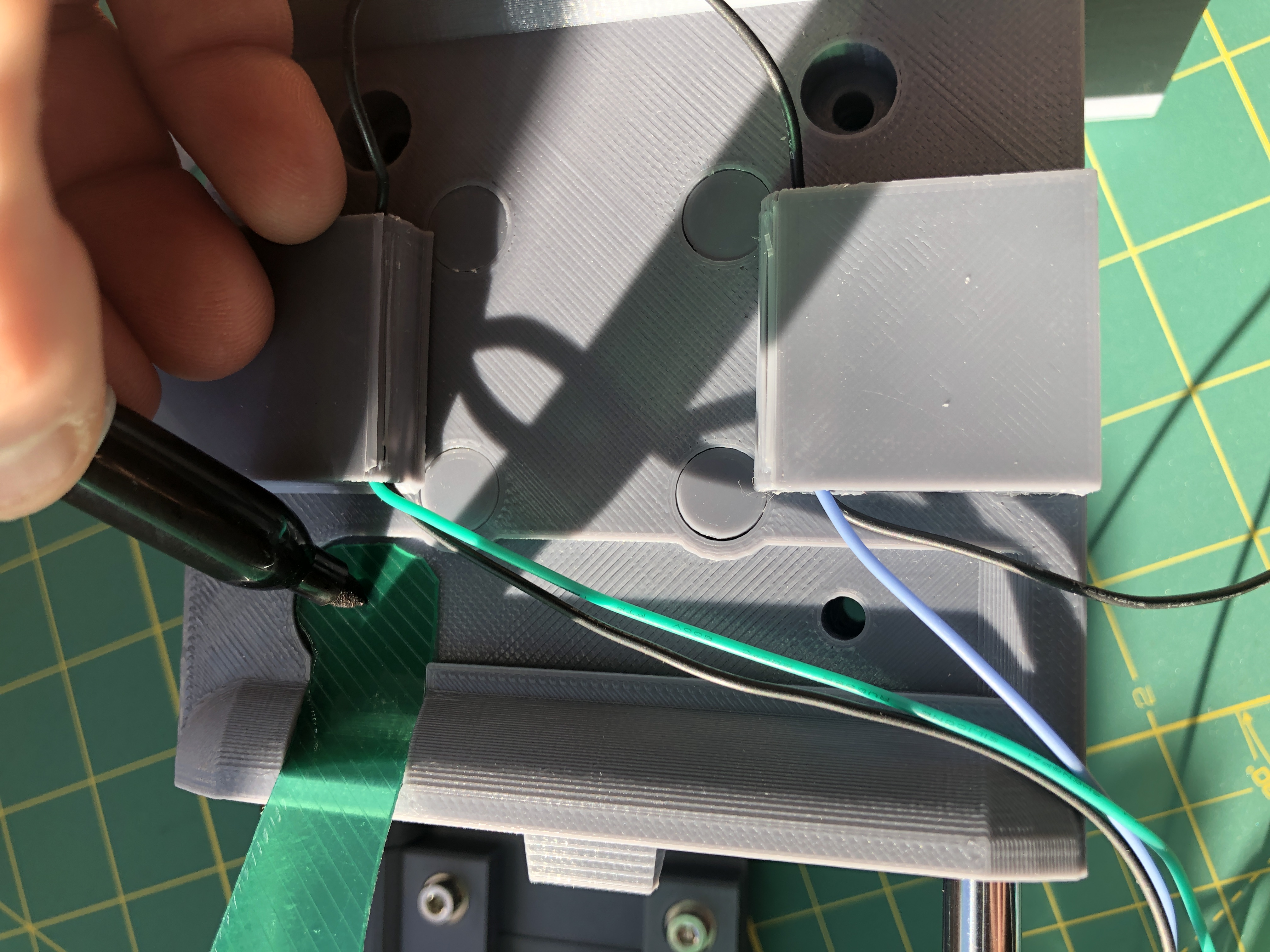
With the wires back out of the terminal, we insert an M4 nut in a tricky spot right where the cables enter.
We can then screw our M4x8 hex screw into it, and use the screw as better leverage to pressure fit the nut into its receptacle (inside, away from the terminal wall).
We can now slide our bendable plastic into a slit right next to the arch opening where cables will enter the terminal.
You can then screw in the M4x8 hex screw to lock the flexible plastic in place.

On the gondola side, the flexible plastic goes on top in a slot the same shape as our gondola_top_cable_management. It helps to cut it to a good fit. Then we mark it where a screw will lock it into place going all the way through the gondola.
We then drill that hole in the bendable plastic.
We put it back in place. We mark and drill another hole on our X axis length meant to extend out the the plastic assembly. This is what it looks like with all our flexible plastic lengths in place.
We can now grab our gondola_top_cable_management and place it directly above our flexible plastic, along with 2 M4x40 hex screw ready to go through the gondola. 2 M4x34 hex screws go into the last 2 outer holes of the gondola. We also use washers for the screws, and at the bottom for the lock nuts.
As previously when we screwed in the belt roller axles, it’s a tricky exercise to tighten these 4 new screws on both sides of the gondola. These screws are holding the gondola together and are meant to be tighter than the axles ones we did earlier. Still though, definitely don’t overtighten and keep an eye on how well your belt rollers are moving.
When this is all done:
We then add a red and green cable going all the way from the bottom terminal, through the gondola, and to our yet to be built pen assembly. We can use the little hoops on the gondola_top_cable_management to keep our wires tidy. I uses electrician’s tape on the flexible plastic to hold the wires.
We finally get to connect our 2 gondola limit switches 🙂 that was a serious tangent… Grab them both, and the ground.
Connect the ground on any ground on the Pi. Then connect the limit switch situated to the left looking at the picture above to Pi pin #3 (GPIO 2). This is in fact the limit switch triggered when the pen assembly reaches it’s right most position and we’ll refer to it as the “right limit switch”. But looking at it this way, it’s on the left :). The other limit switch, the “left limit switch” situated to the right on this picture, goes to Pi pin #5 (GPIO 3).
We can now power the plotter once more and head to its web interface. The Mechanics sections will show the state of the limit switches. You can trigger the switches yourself manually and verify that their state is toggled as you do so (the state isn’t reflected on the web interface immediately, it might take a second or 2 to show).
9. Servo Motor
Electrical:
servo motor
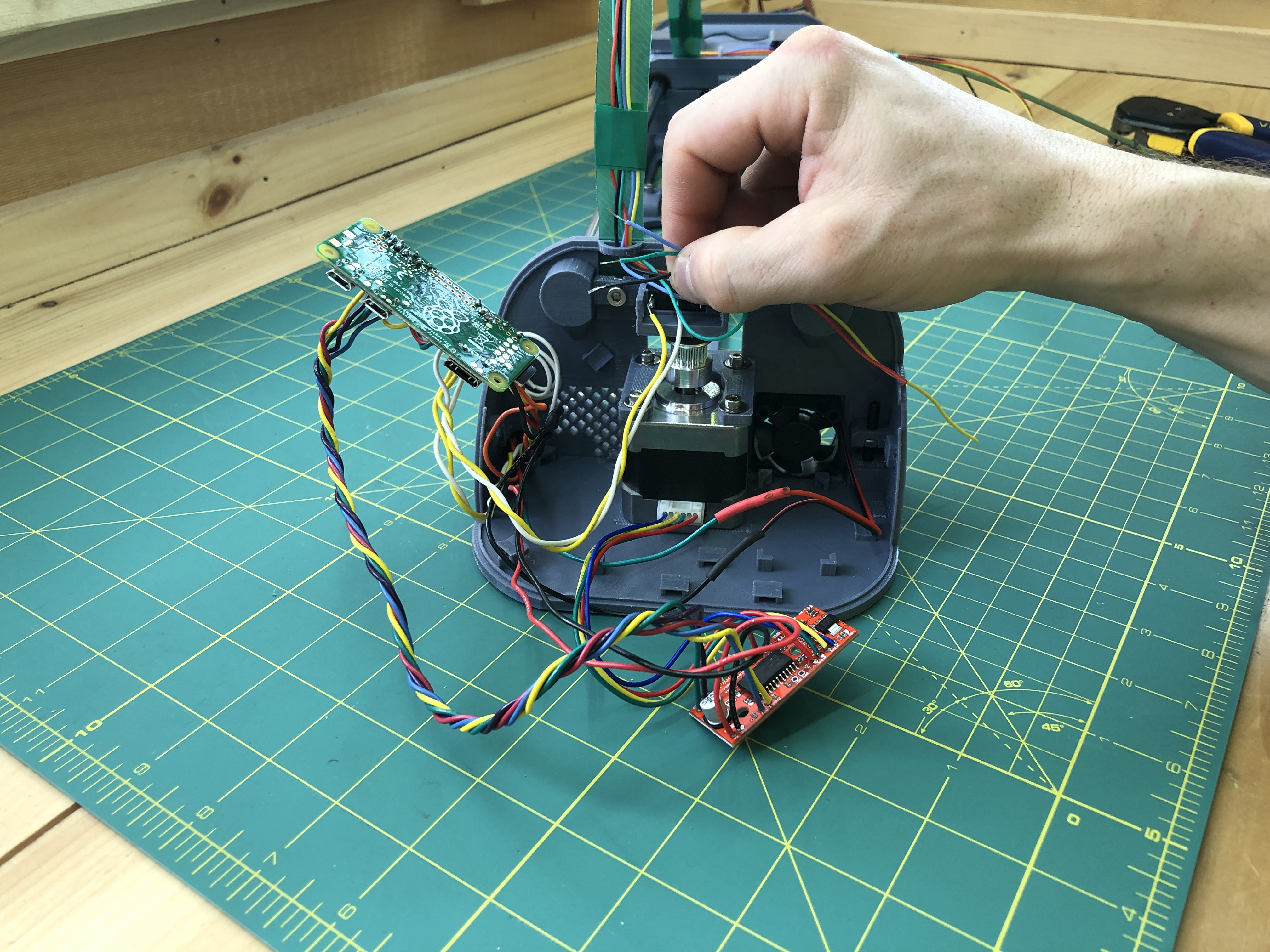
We’re about to do our last wiring :). Grab the red and yellow wires you have brought into the bottom terminal from the gondola (the ones that go all the way out to the pen assembly). Connect the red one to Pi pin #4 (5V power), and the yellow one to Pi pin #16 (GPIO 23).
Where the pen assembly will go, we cut and strip the wires, you’ll need to use your X axis linear rods to estimate where to cut. We will actually be terminating these wires with a dupont connector matching the servo motor’s. This is because these servos will wear and die. They are a part with limited cycles and so we want it to be easily replaceable.
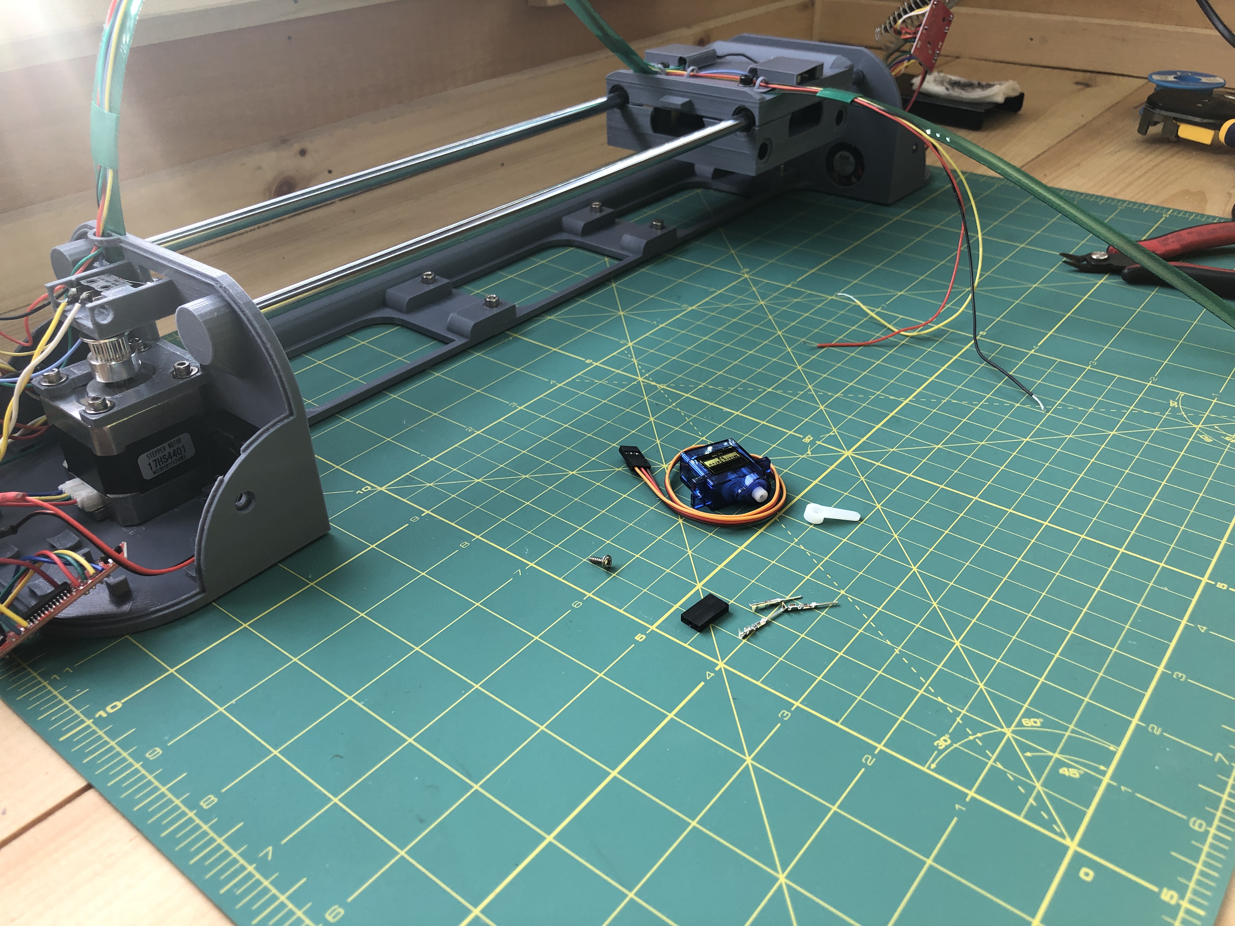
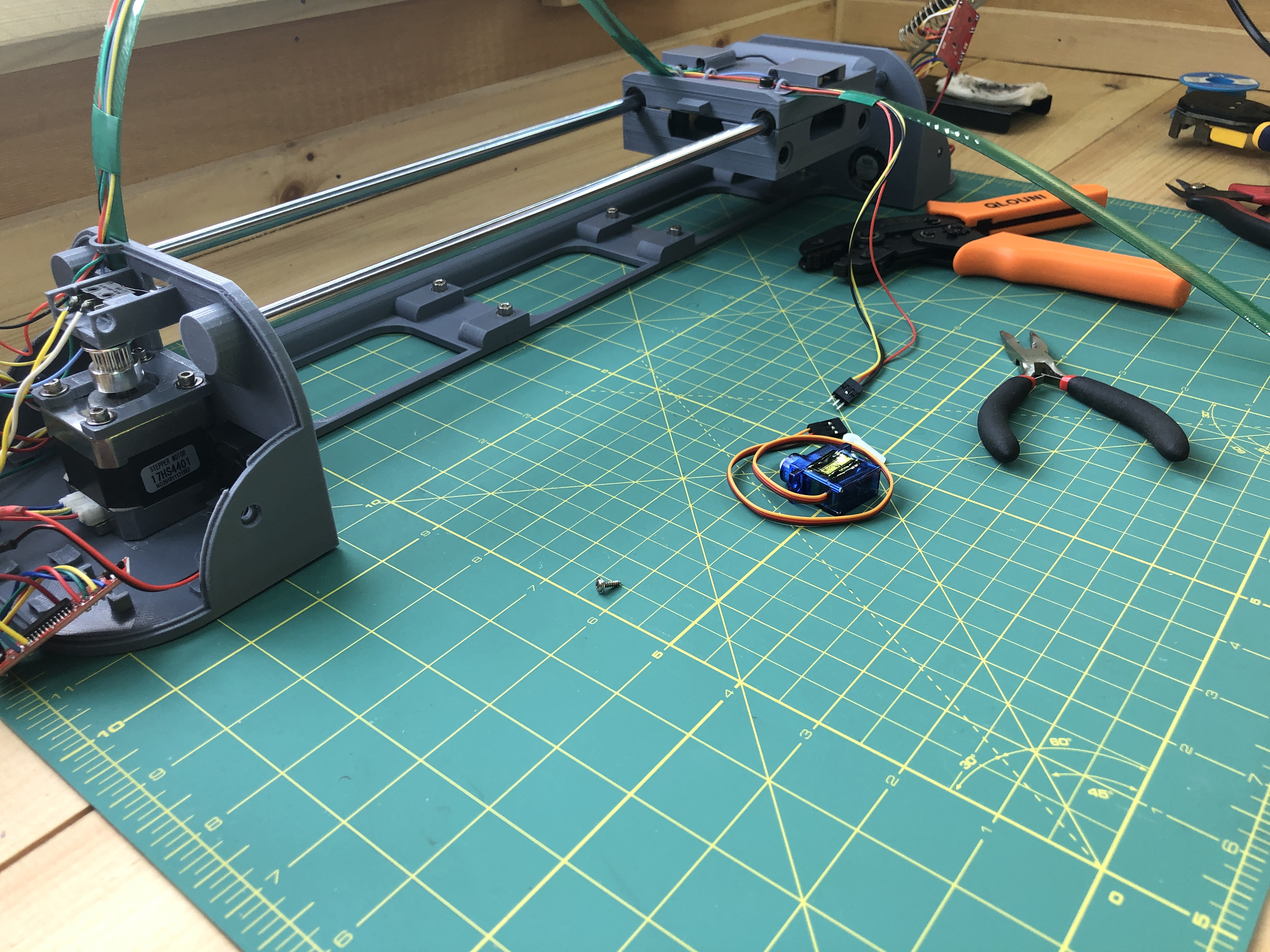
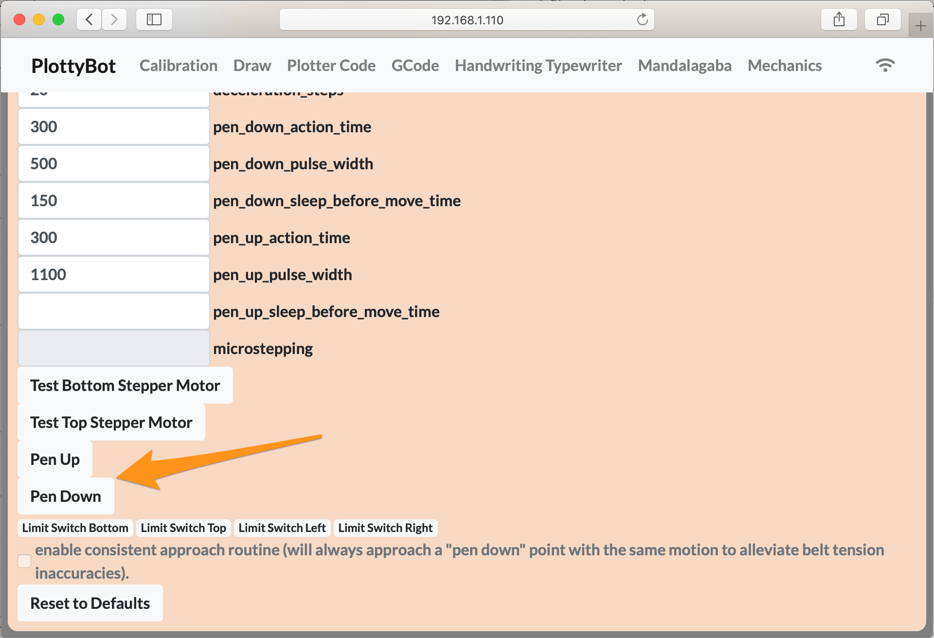
When it’s connected, we can power our plotter once more and head back to the web interface. The Mechanics sections has “Pen Up” and “Pen Down” buttons to test the servo with.
We are done with wiring! We now get to tidy up our terminals by placing components in their holders and managing wires. There is no right solution for the wires, the model simply has opportunities for small zip ties. I used a glue gun to hold the components in place on the corners which aren’t covered, I usually prefer sugru mouldable glue but I didn’t have any.

My Pi is a a bit of an ill fit here but that’s ok.
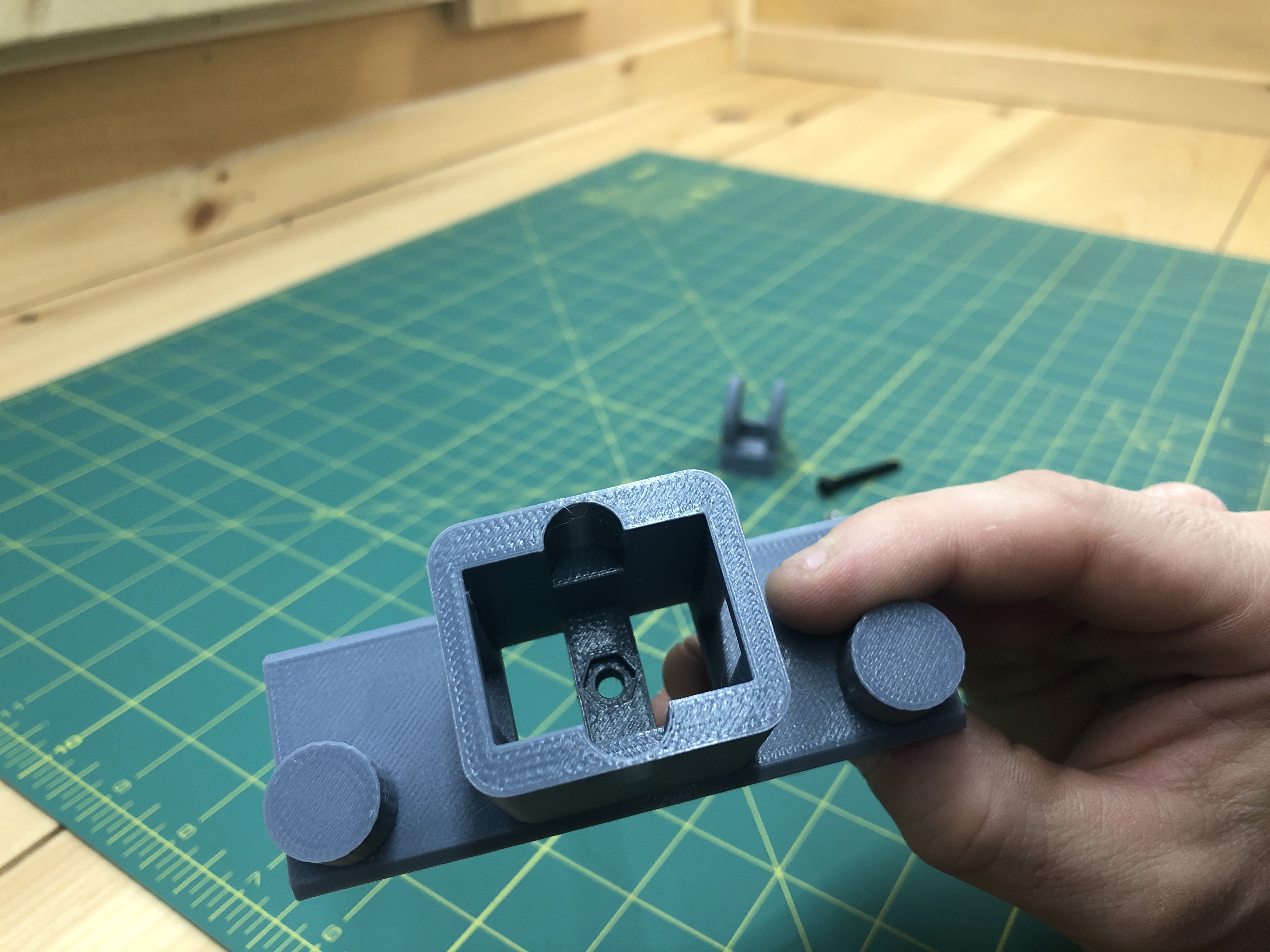
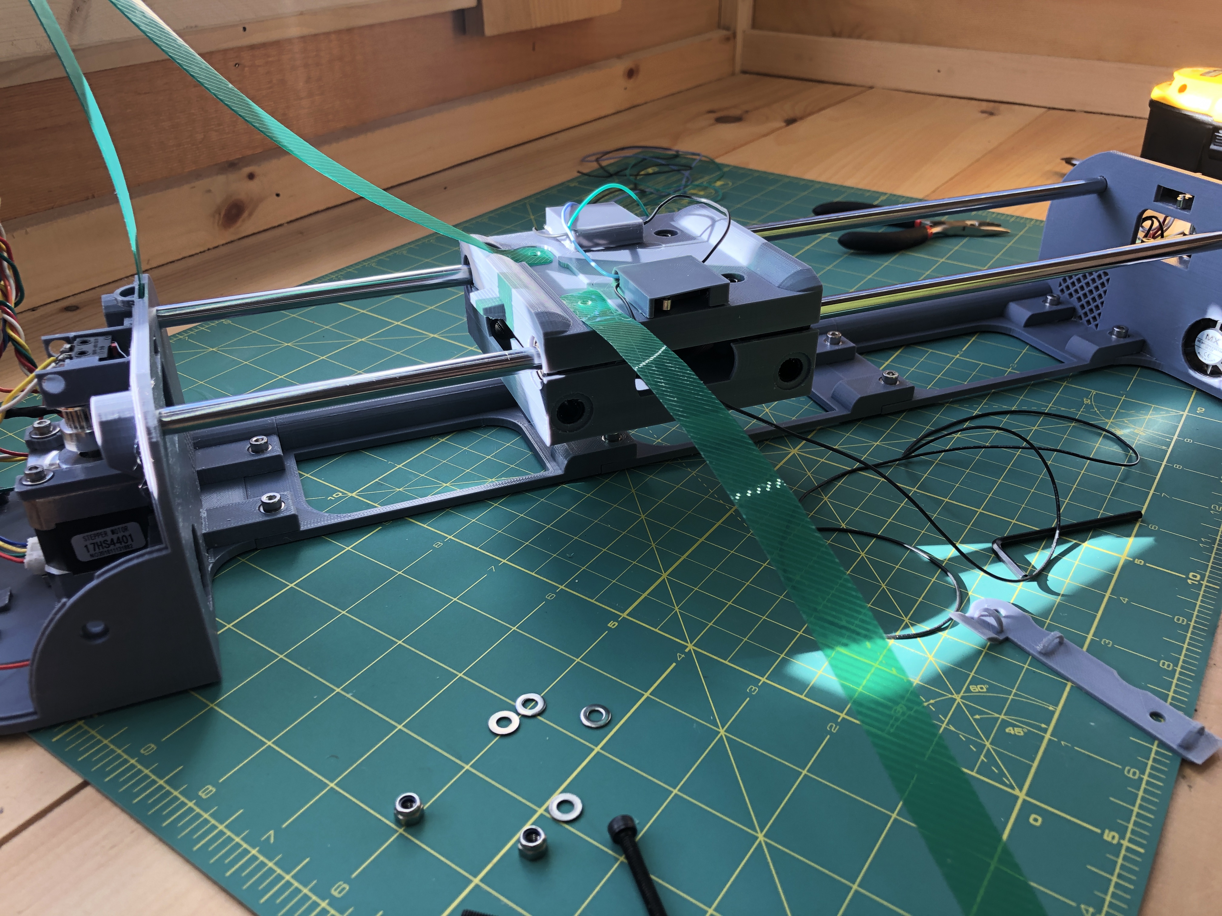
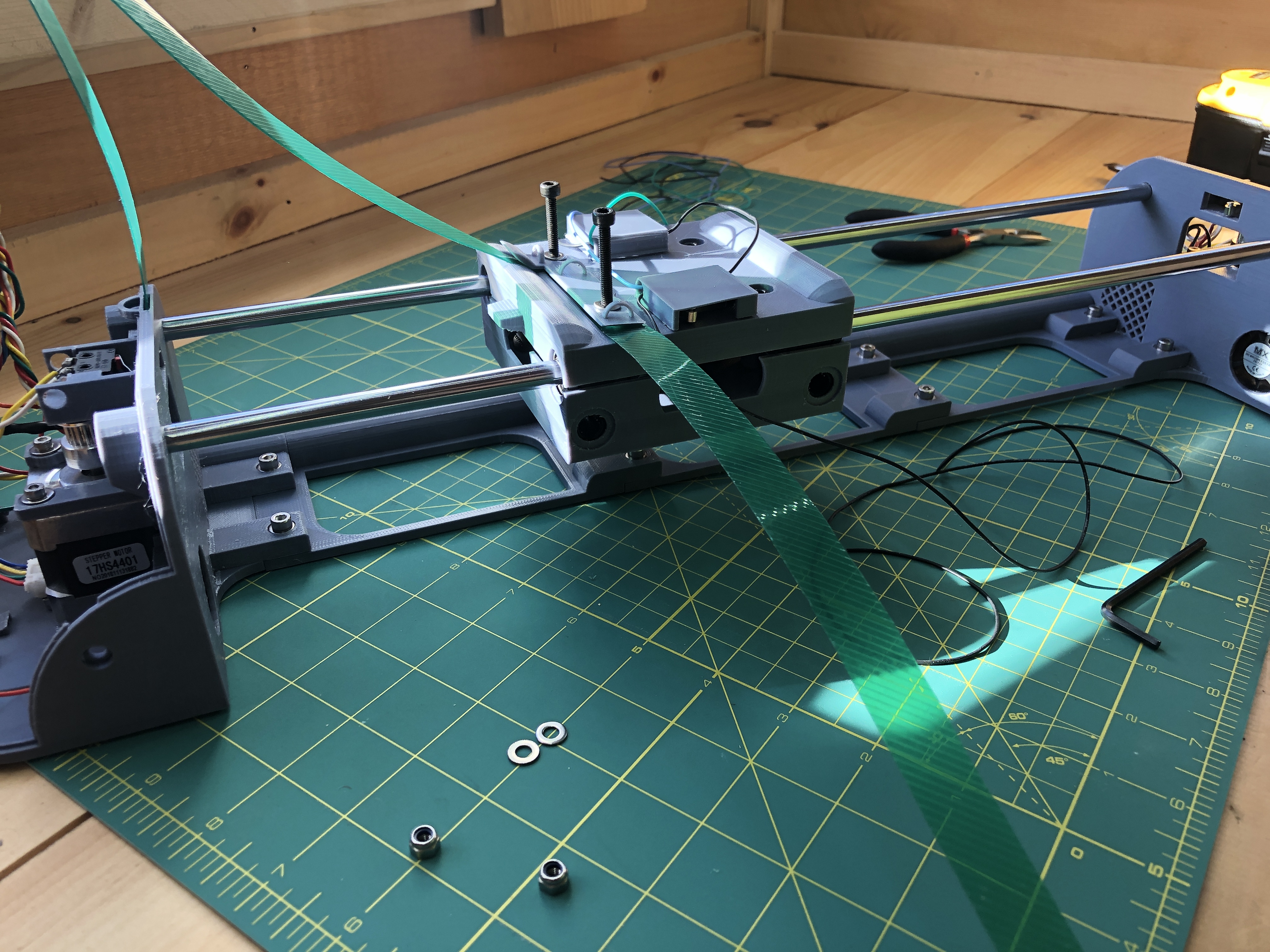
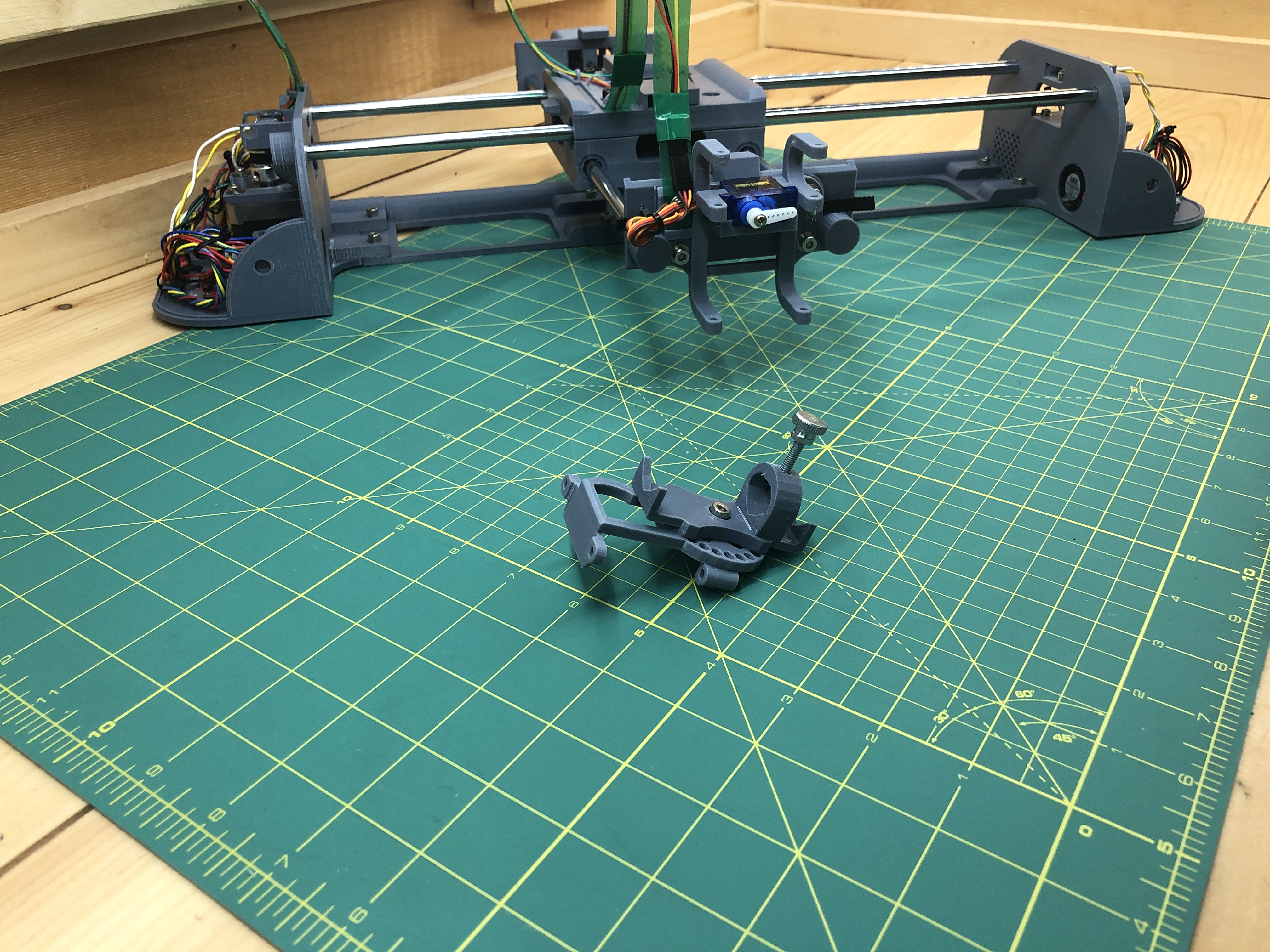
10. Pen Assembly
Hardware:
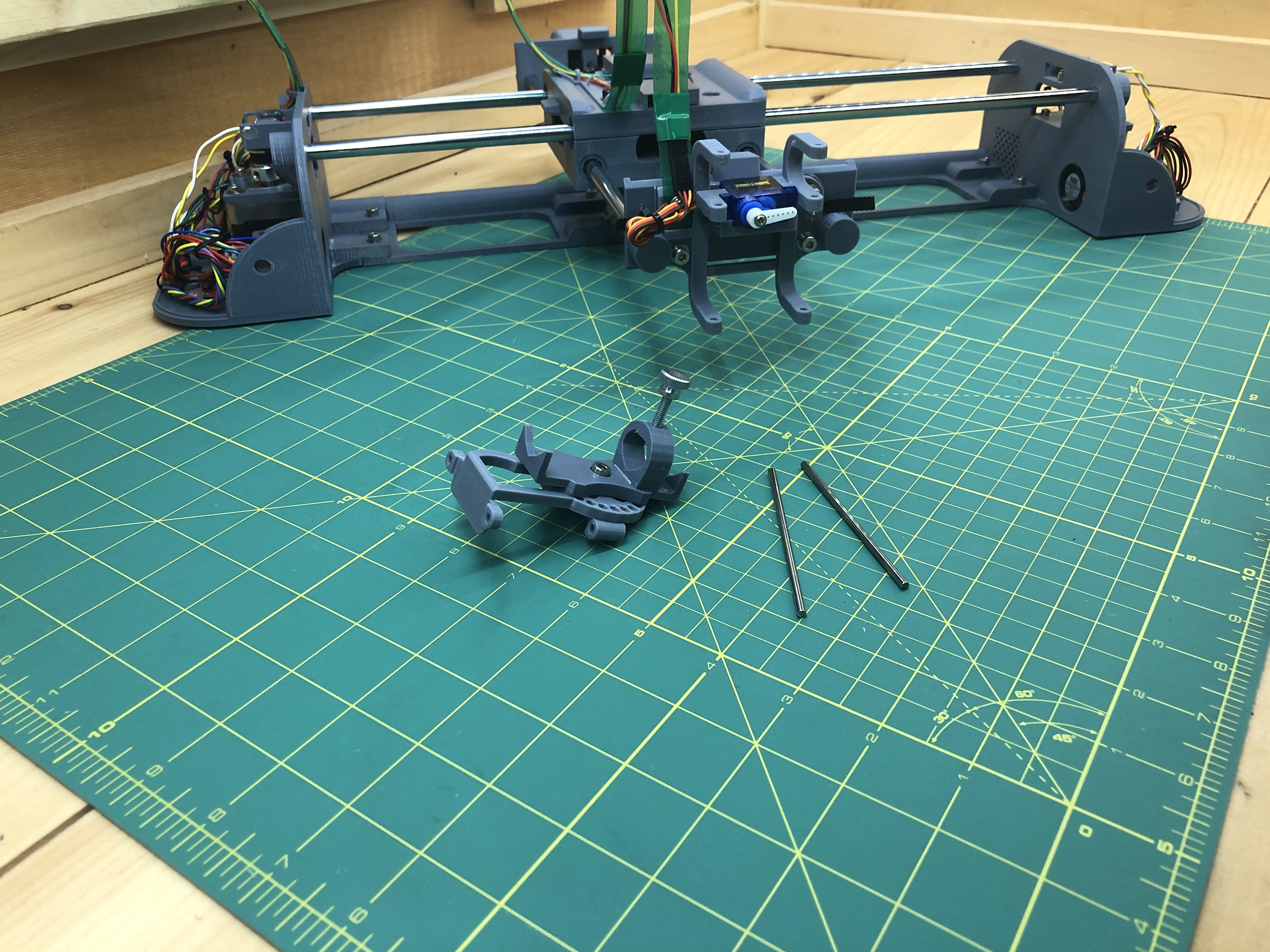
2 8x350mm linear rods
2 3x100mm linear rods
1 GT2 belt
1 M4x8 hex screw
1 M4 pen holder hand tightening screw (or a regular less fancy M4 screw)
2 M4 nut
4 M4x12 hex screws
4 washers
3D printed:
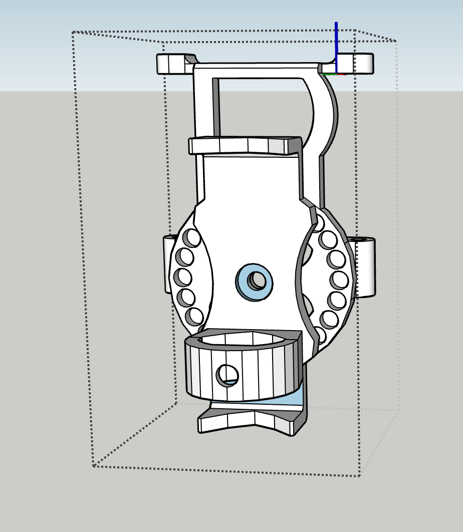
front_assembly_x1
front_assembly_servo_holder_x1
front_assembly_pen_slider_x1
front_assembly_pen_holder_x1
Previously build:
the back assembly belt roller from step #3.
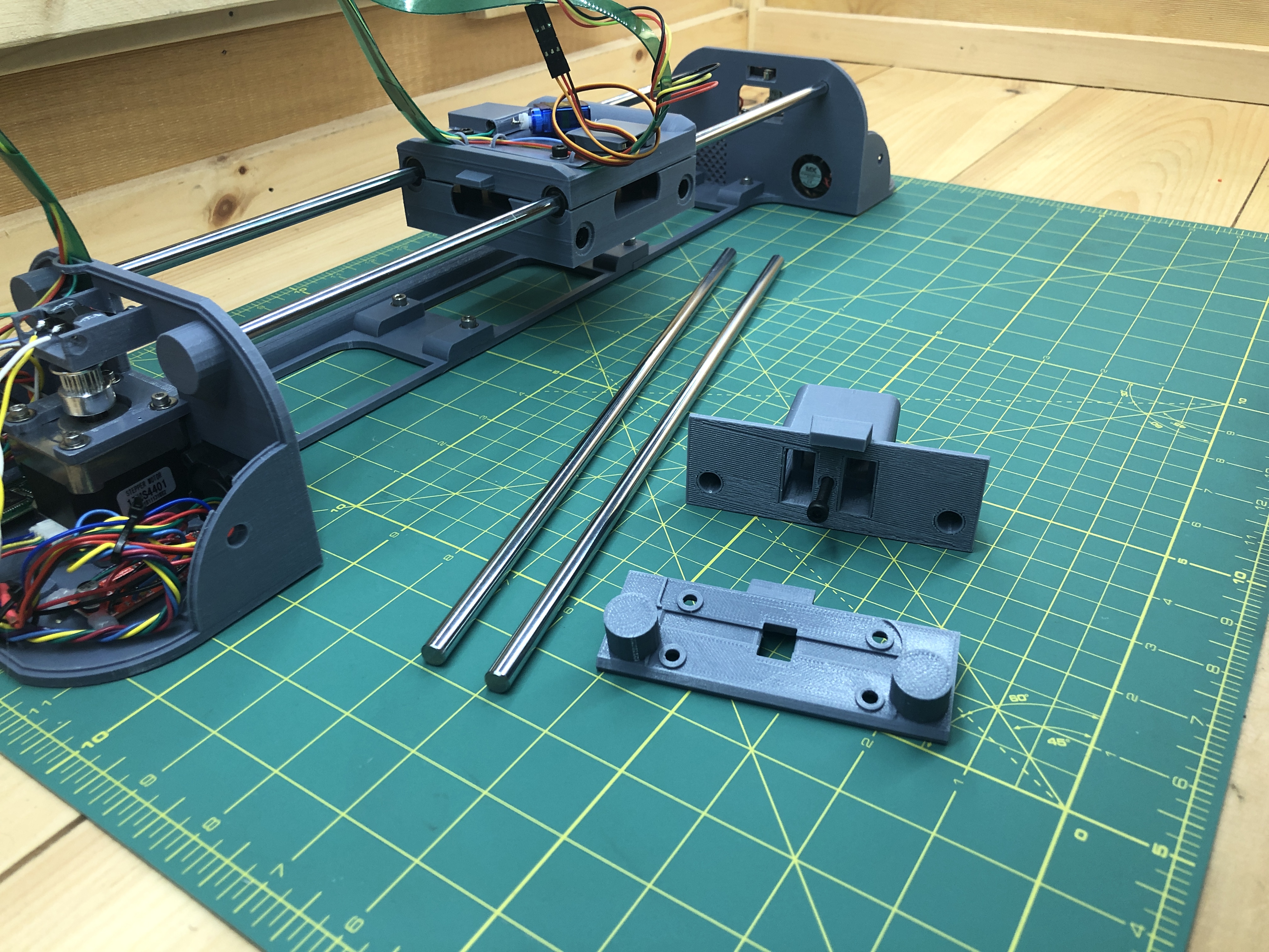
Run the rods through the gondola.
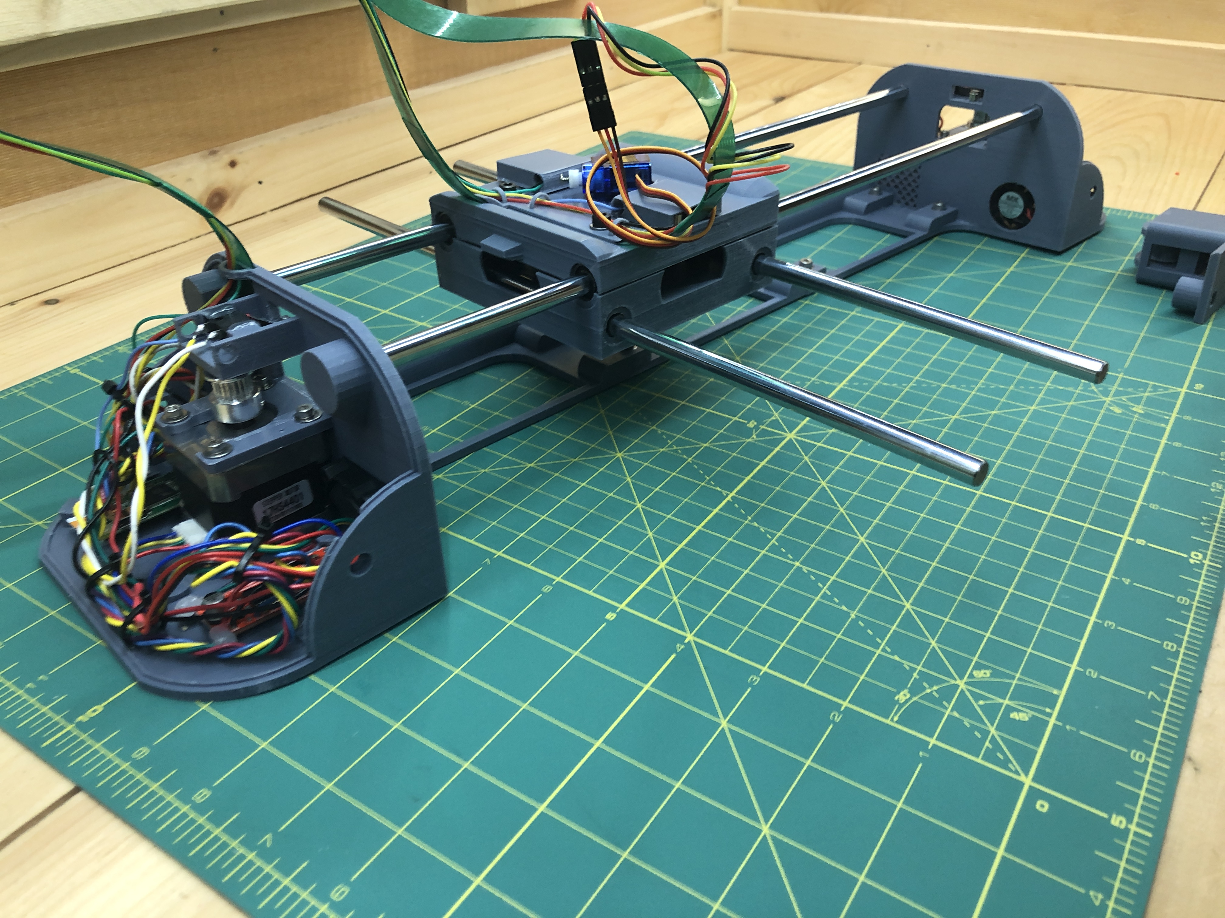
Add the back assembly belt roller.

And then the front_assembly.

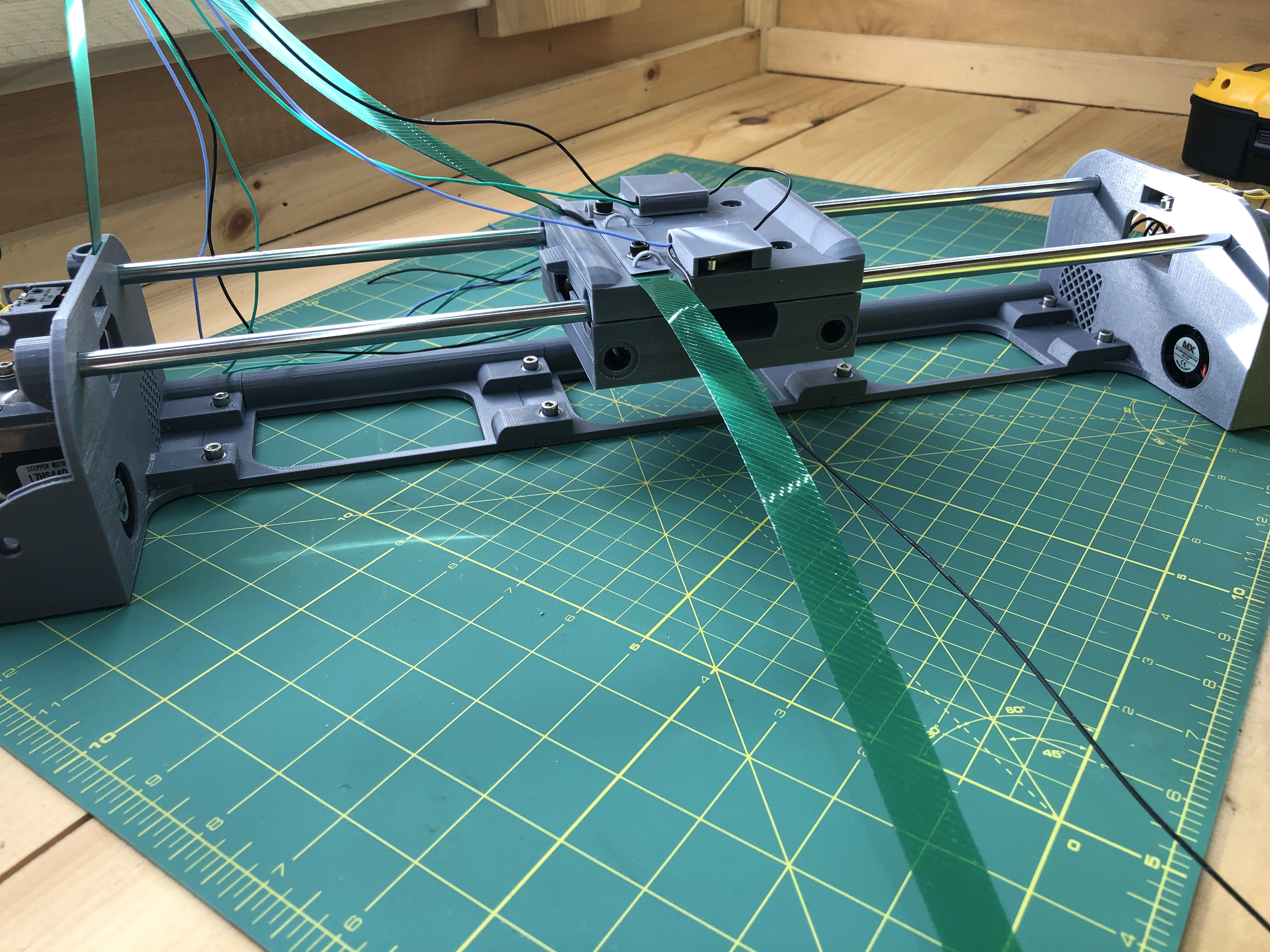
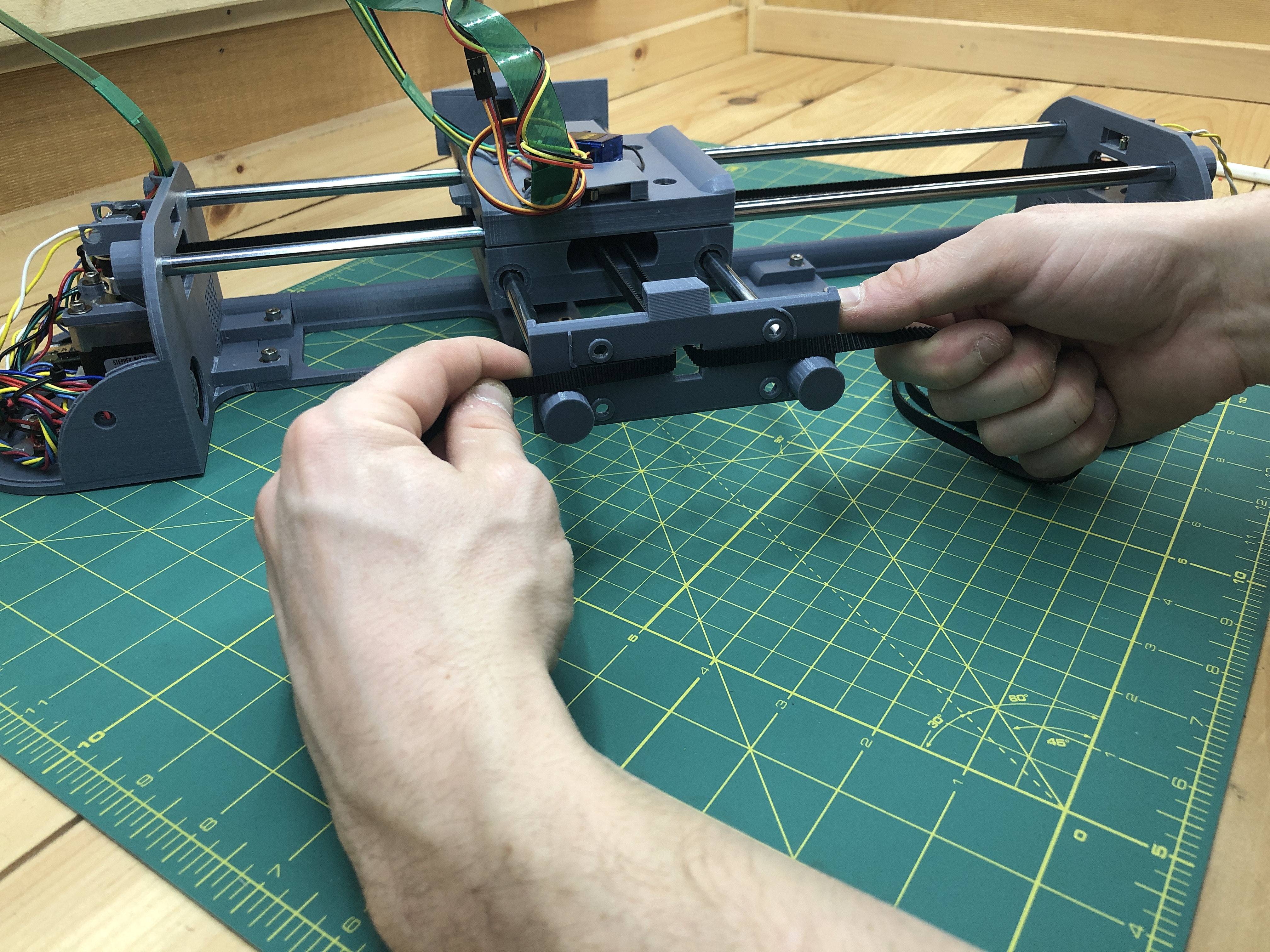
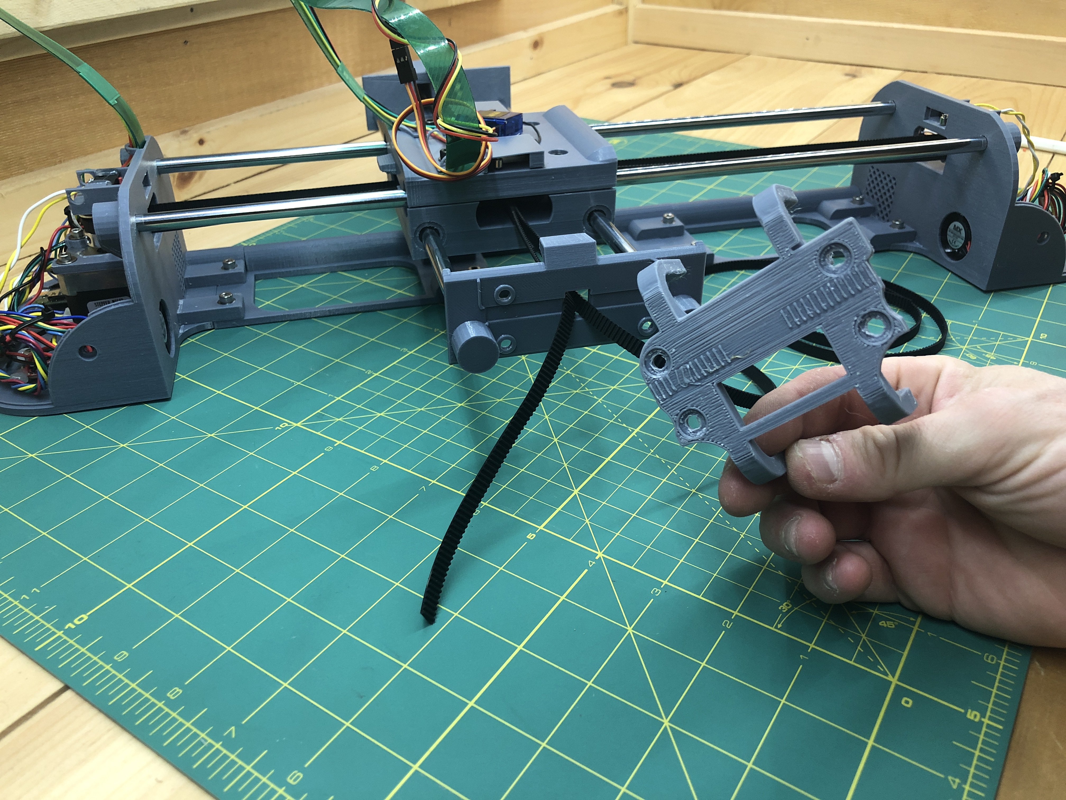
Get your GT2 belt.
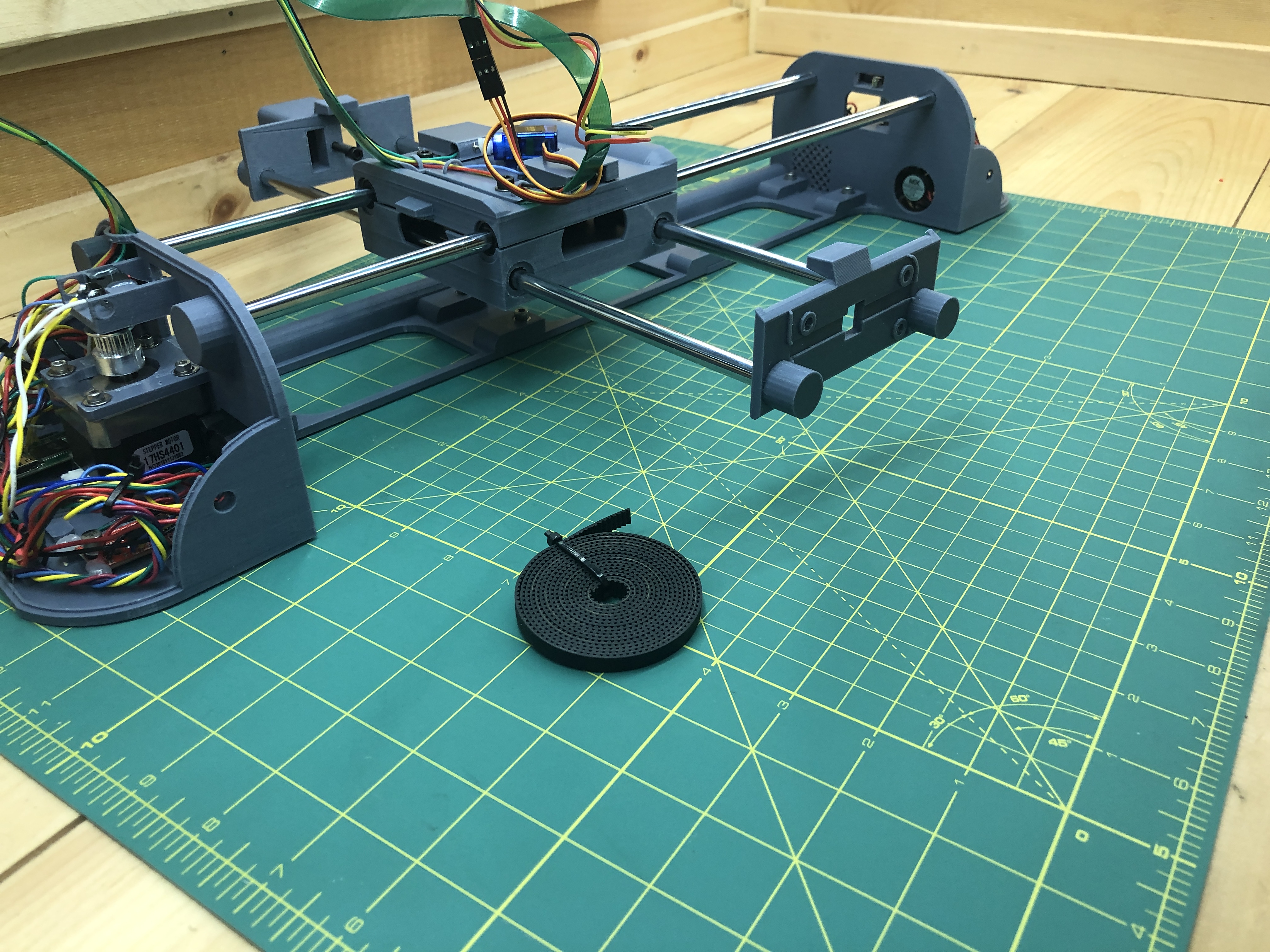
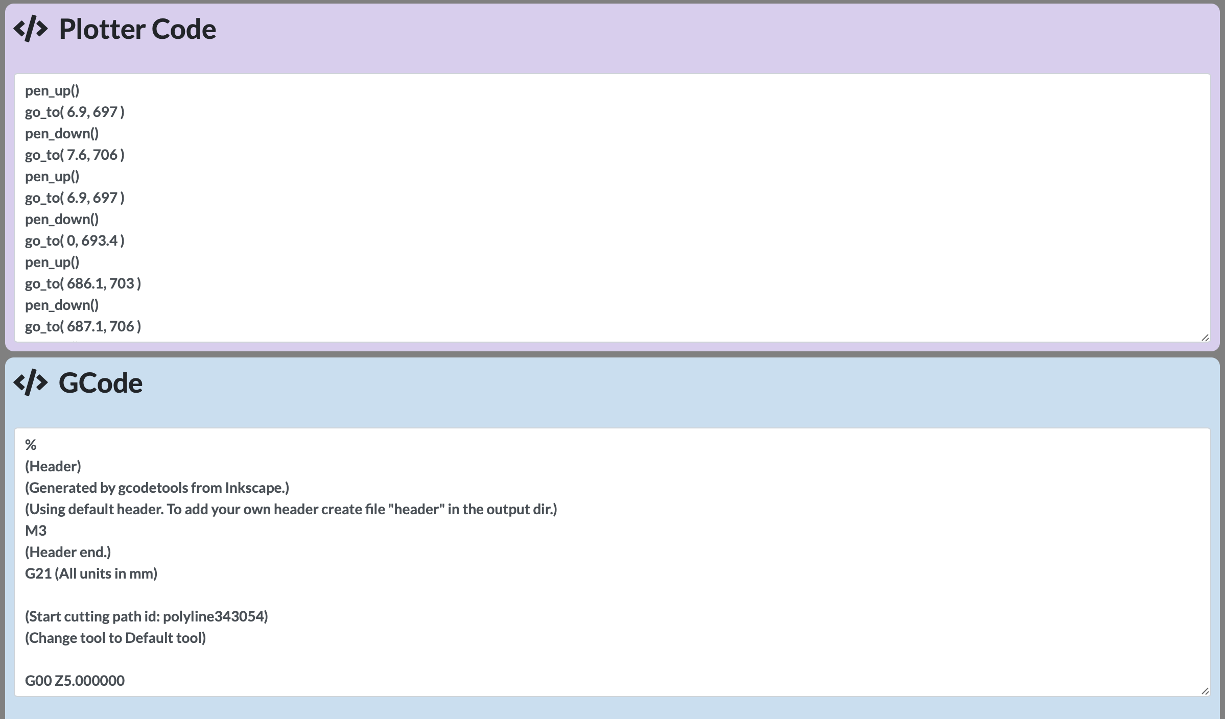
Run it through the plotter and out the front assembly. It’s hard to describe in words exactly how so here’s a schema:
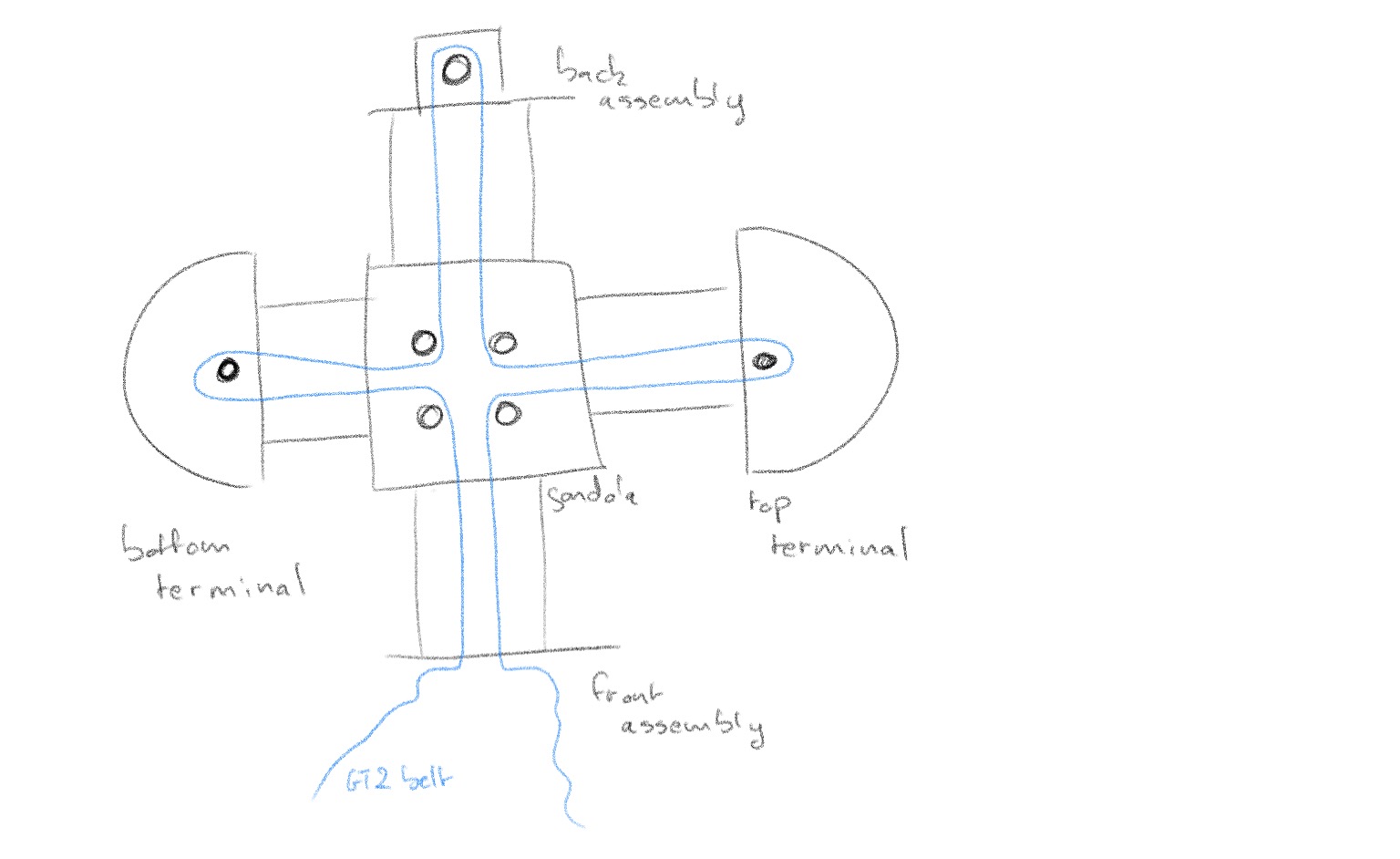
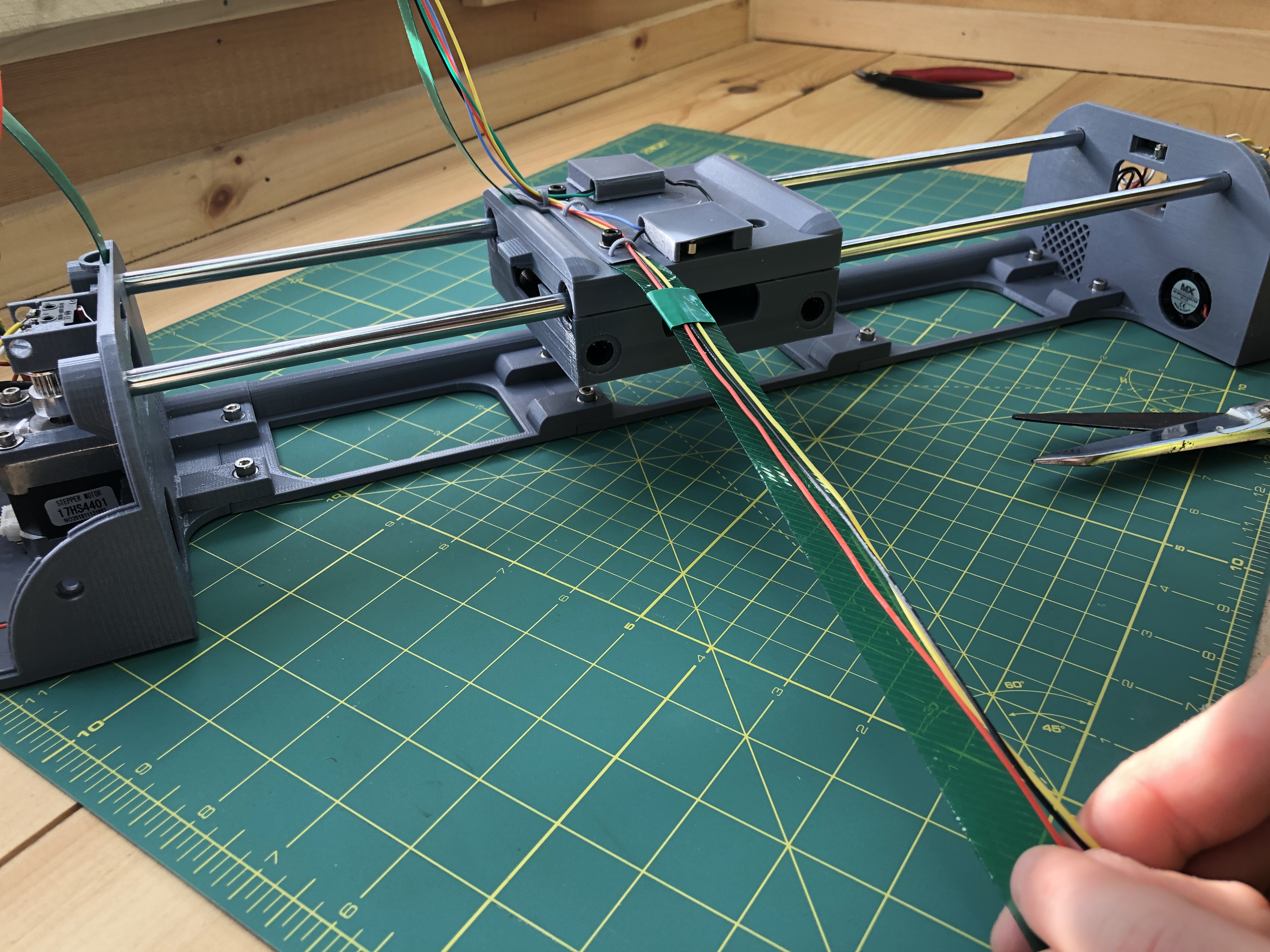
This is an annoying thing to do with several attempts to be expected. But it’s not hard. I find attaching a bent but rigid guide to my belt helpful. You wand to make sure that the belt doesn’t twist and is always flat with its teeth eventually facing the stepper motor pulley.
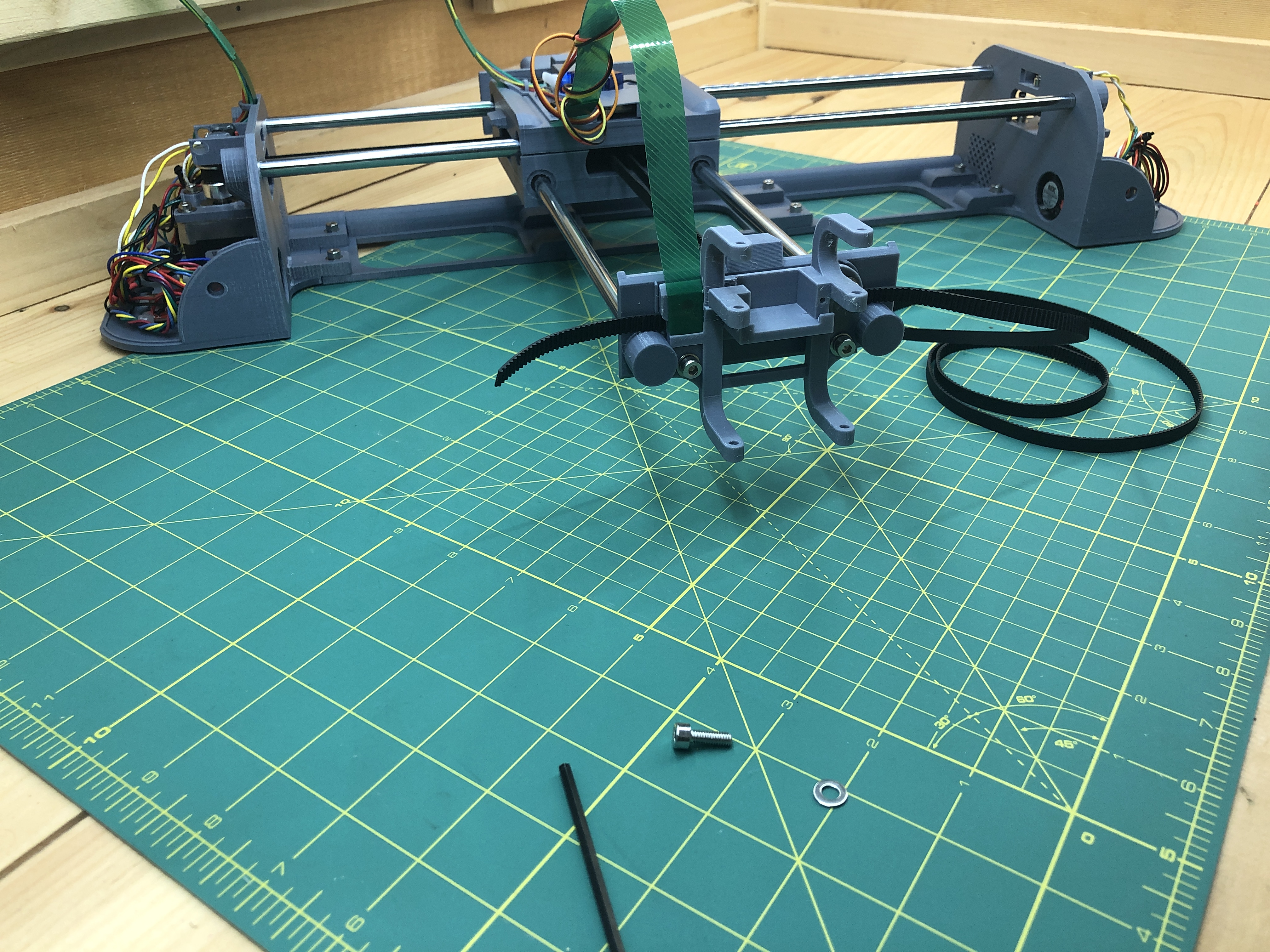
Pressure fit 4 M4 nut into receptacles in the back of the front_assembly.
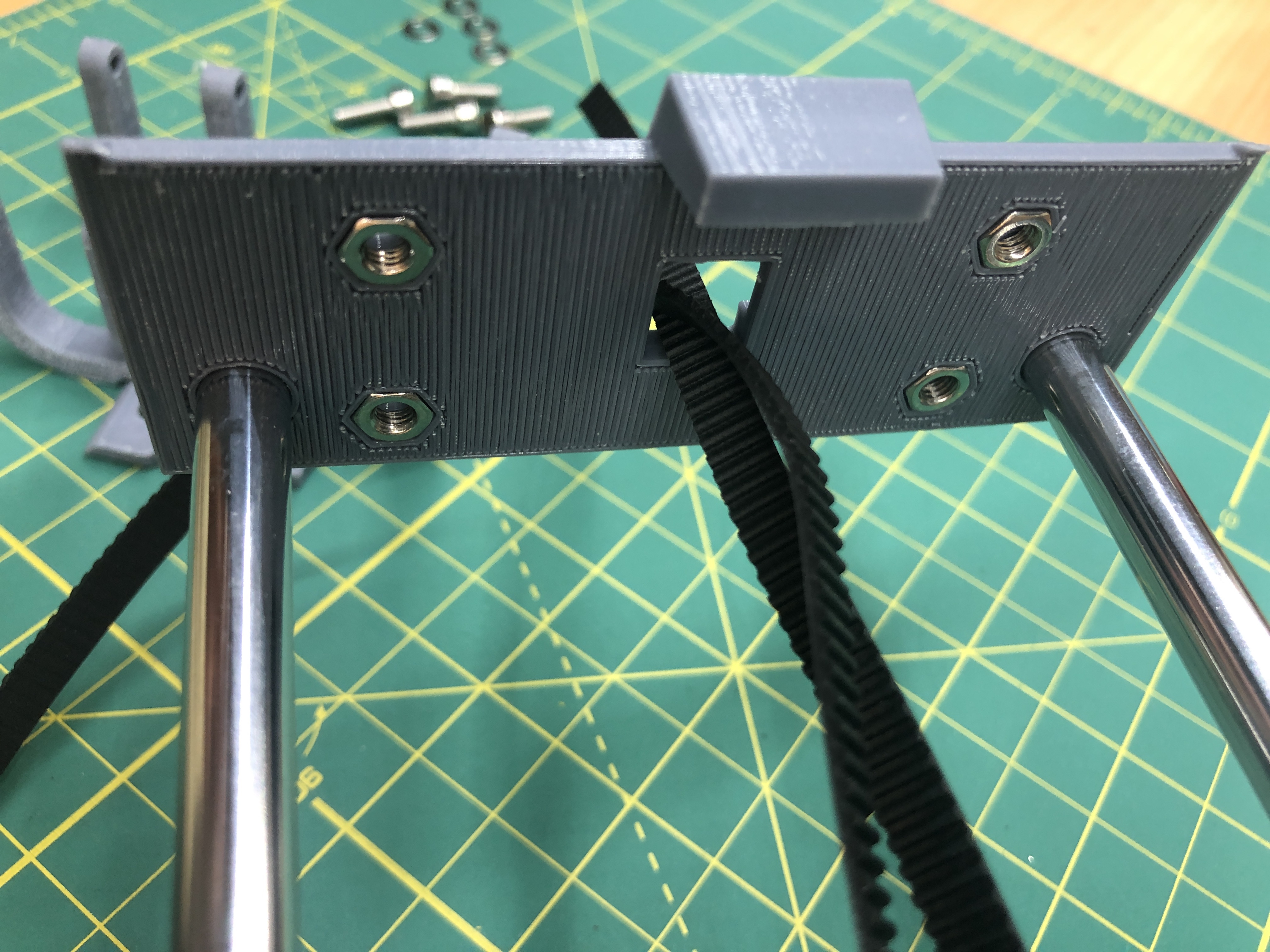
Grab your front_assembly_servo_holder. It has teeth in the back to hold the GT2 belt in place when pressed against it.
Put it against the front_assembly and screw in the bottom 2 holes with M4x12 screws and washers. You want to hold the belt tight until these 2 bottom screws are in place and holding it for you.
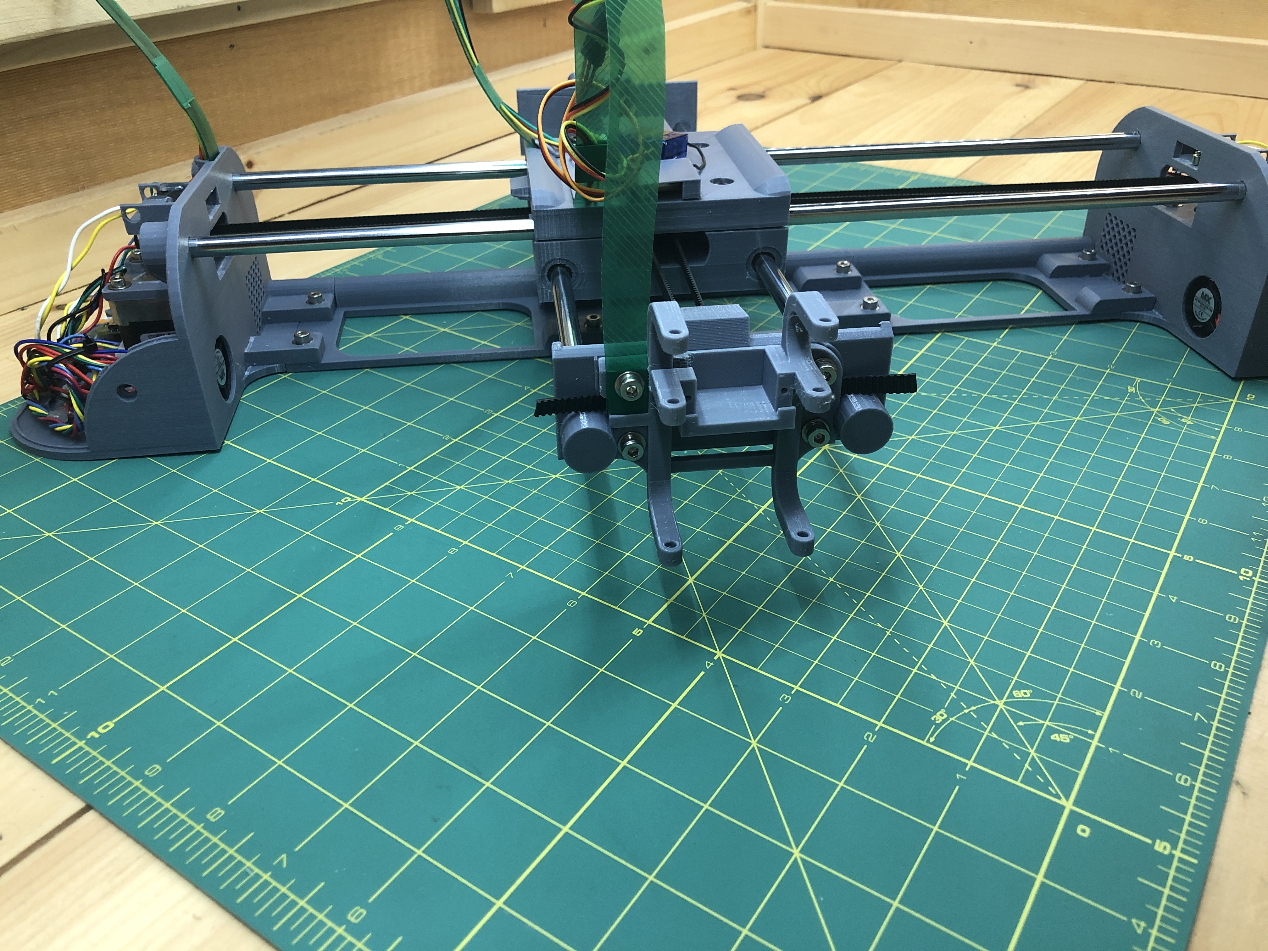
Slide in the flexible plastic carrying our servo wires from the gondola, drill a hole in your flexible plastic matching that of the front_assembly_servo_holder, as you’ve done before. Screw in the top 2 holes with 2 more M4x12 hex screws and washers.
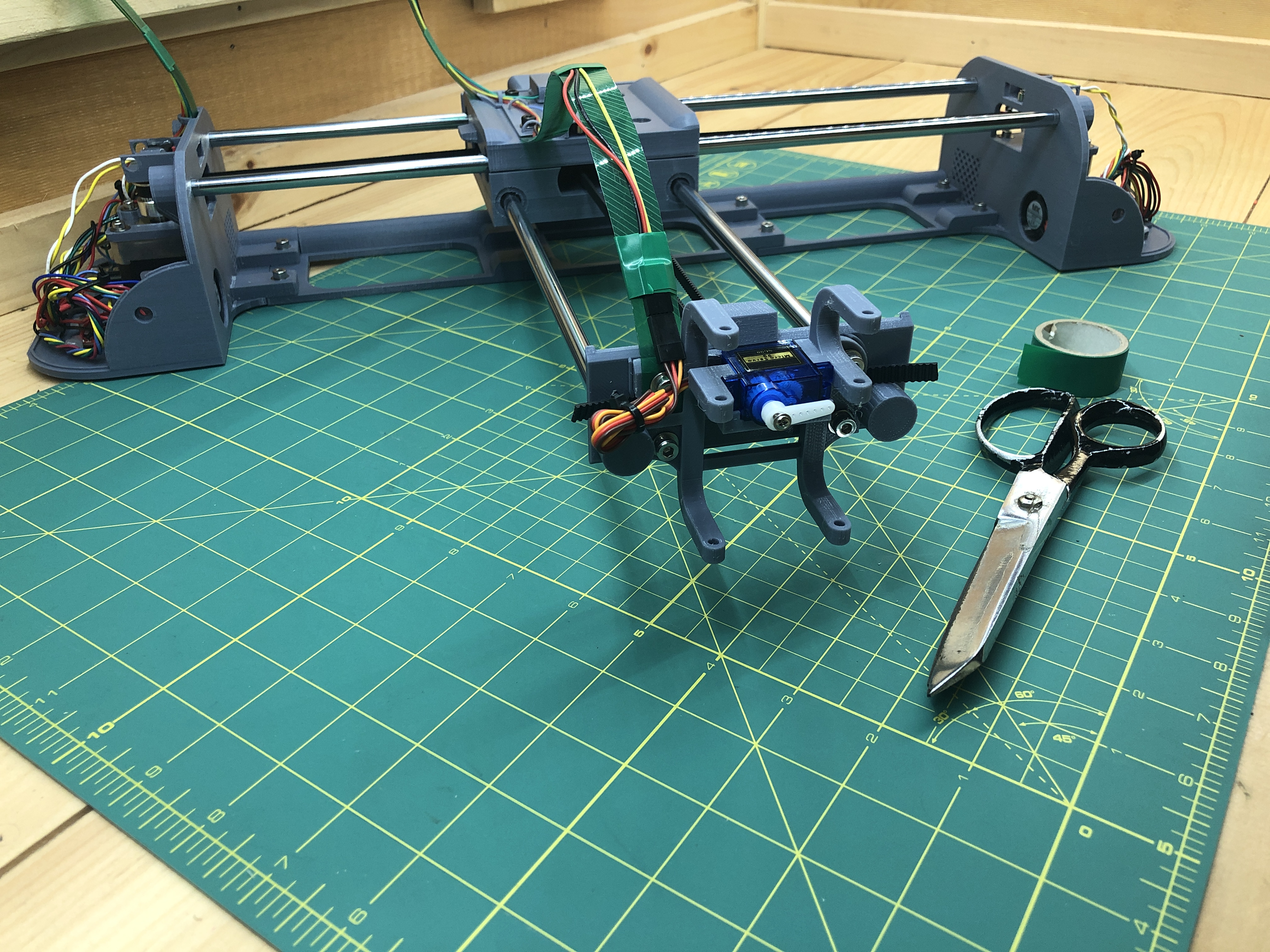
Put your servo motor in (without the arm).

Plug in the servo, plug in your plotter, go to the web interface, and click the “Pen Down” button. Now put in the servo’s arm horizontally and screw it in.

Tidy up the servo wires.
Pressure fit an M4 nut in the receptacle in the back of front_assembly_pen_slider.
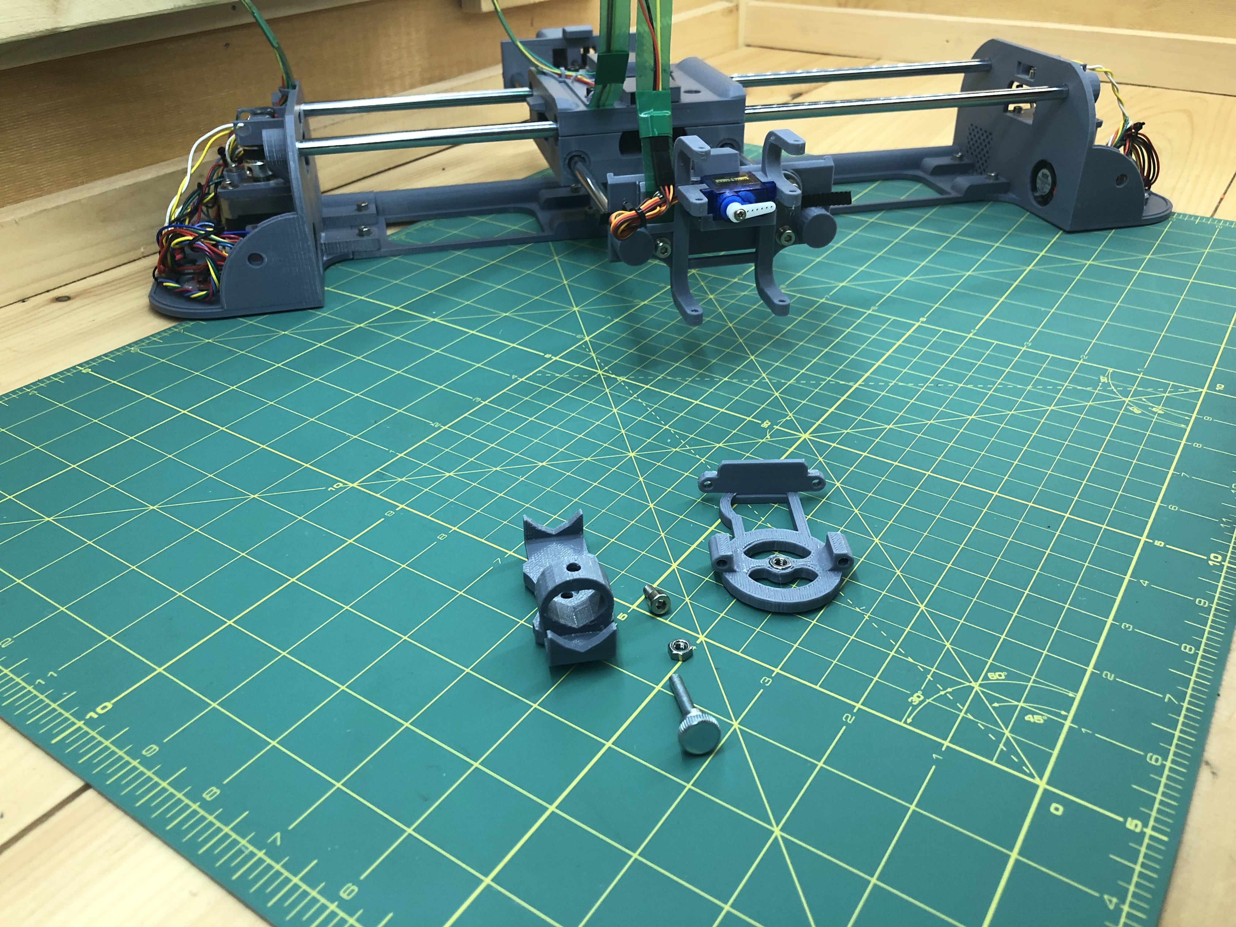
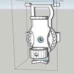
Place front_assembly_pen_holder on top of front_assembly_pen_slider, it has a circle of little dots matching little holes meant to adjust rotation of the writing instrument. We’ll just do a straight angle for now.
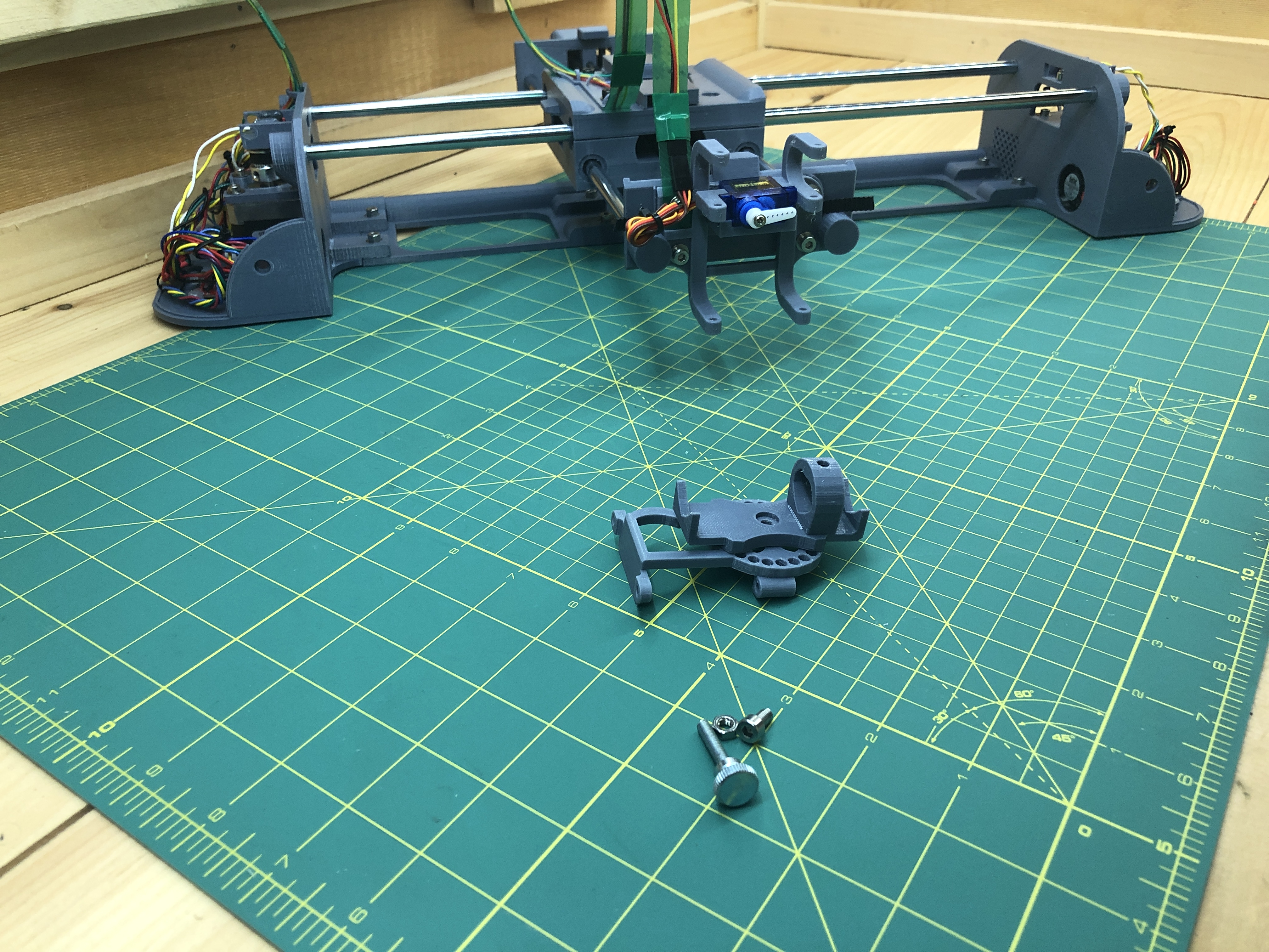
Screw it in place with an M4x8 hex screw.
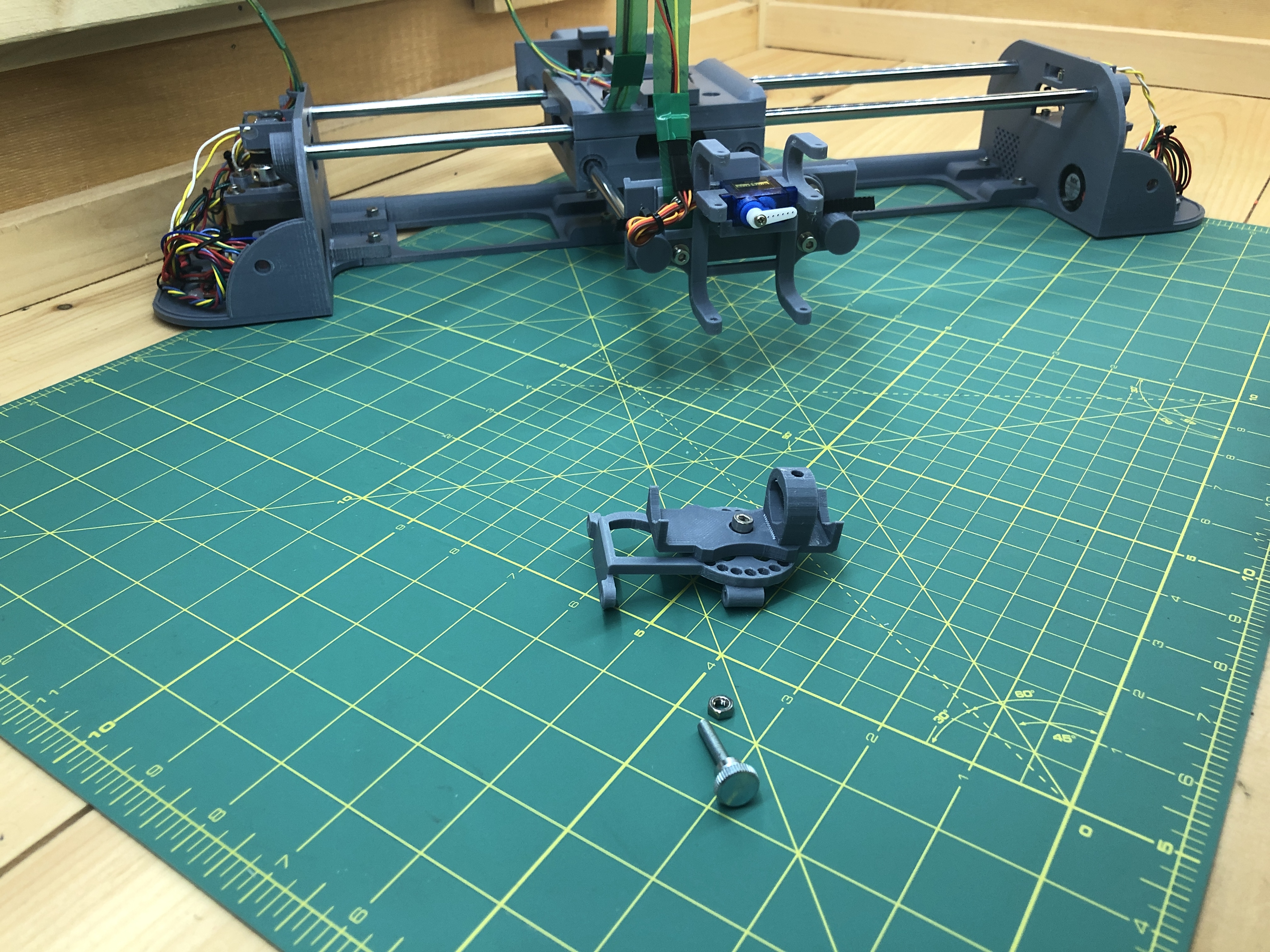
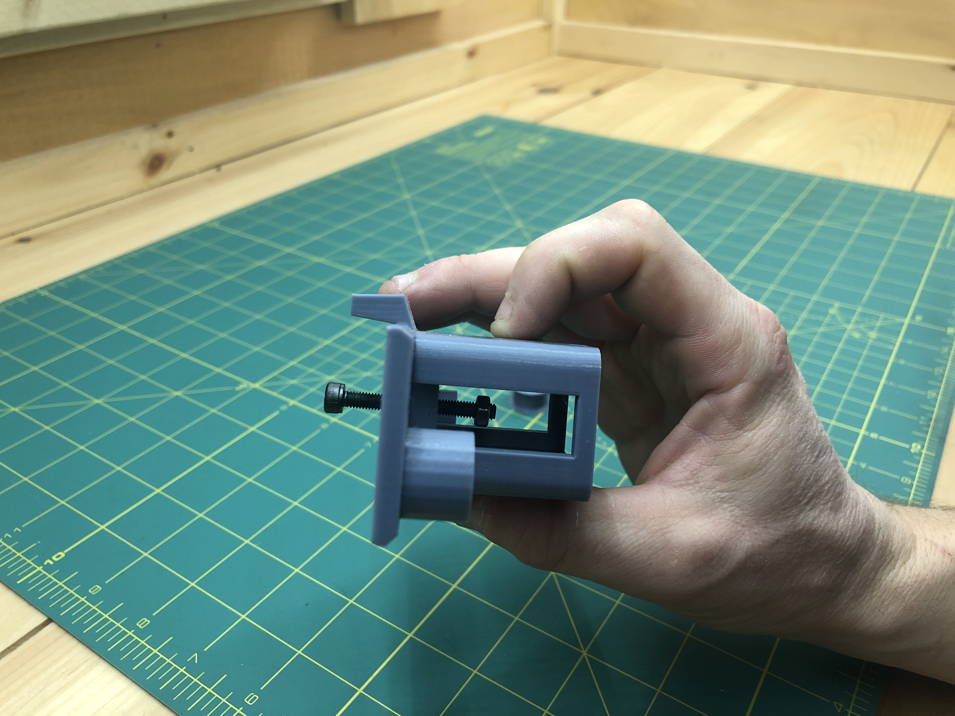
Inside where the pen will be held is a receptacle for another M4 nut, pressure fit one and screw it a hand tightening M4 screw (or a regular M4 screw if you want).
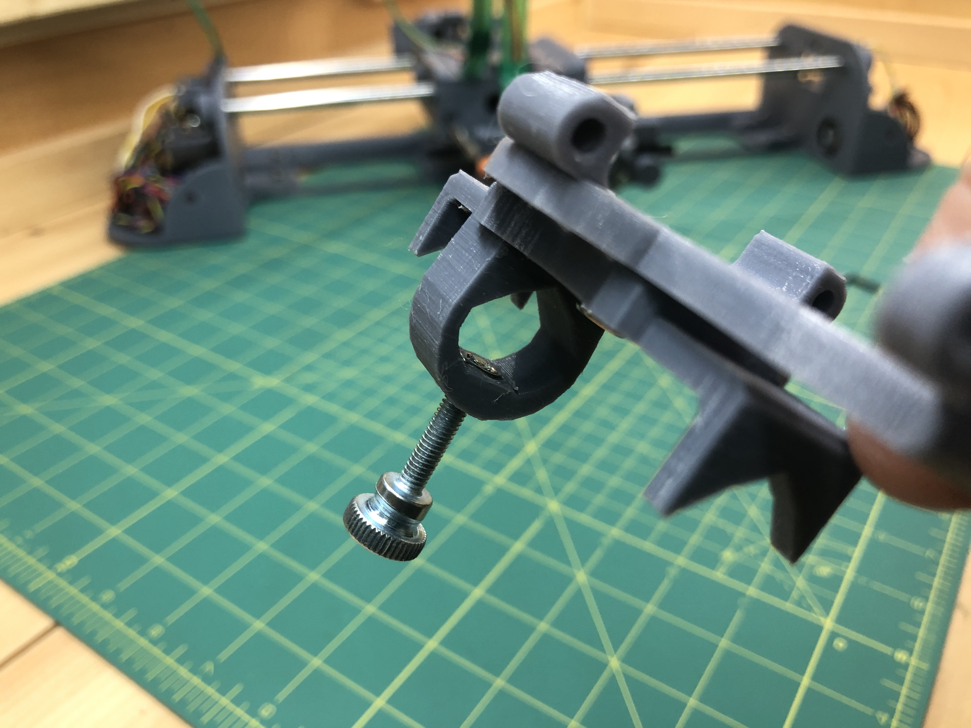
Looking good.
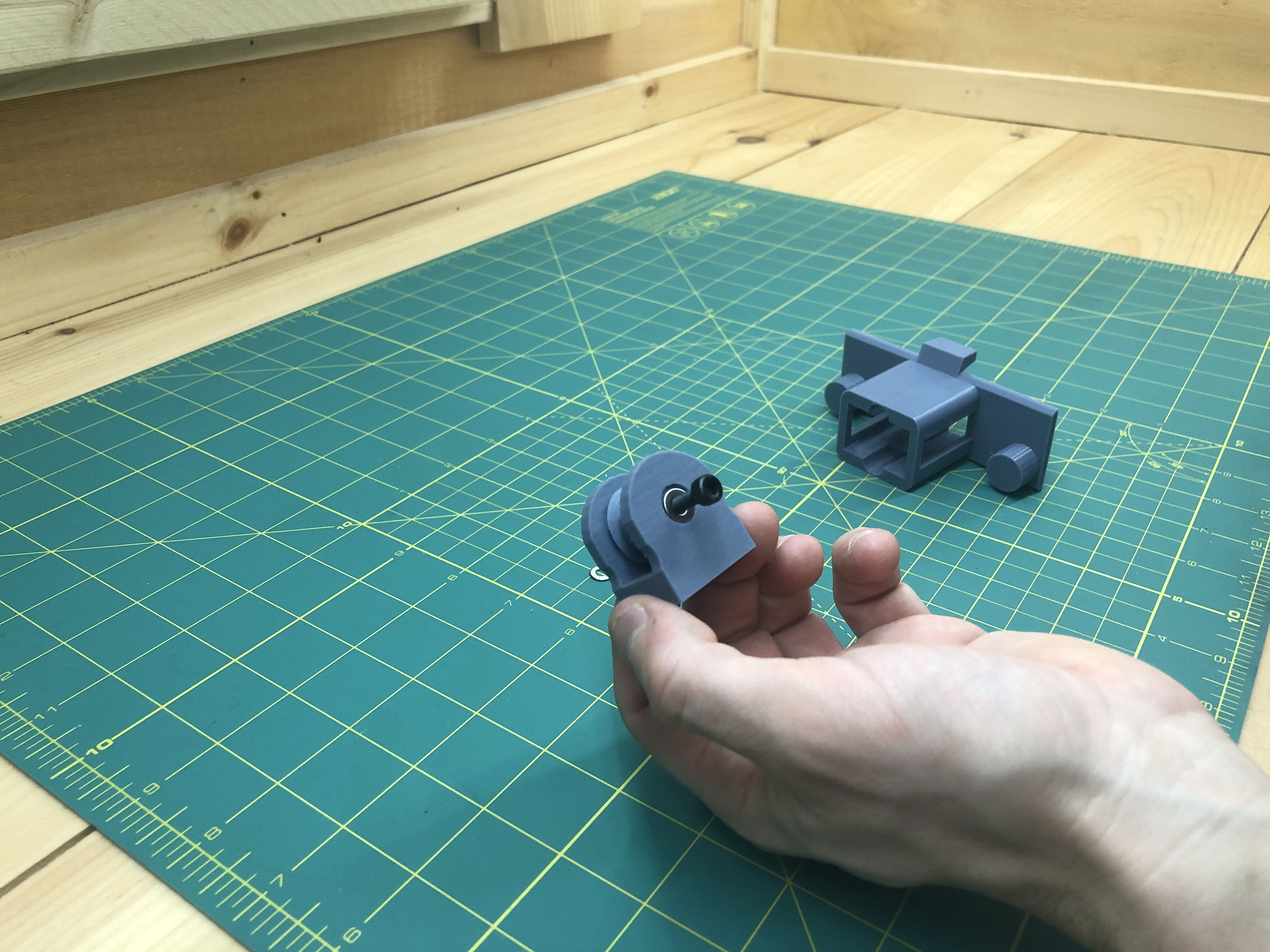
Grab 2 M3x100mm linear rods (you can salvage some from old CD drives).
The rods need to slide without friction as much as possible. Until they do, you can hand drill the holes of your newly built pen holder. Be extremely careful now to remove too much material or your pen holder will have play.
Grab 2 sacrificial click pens. We’ll cannibalize them for their springs.
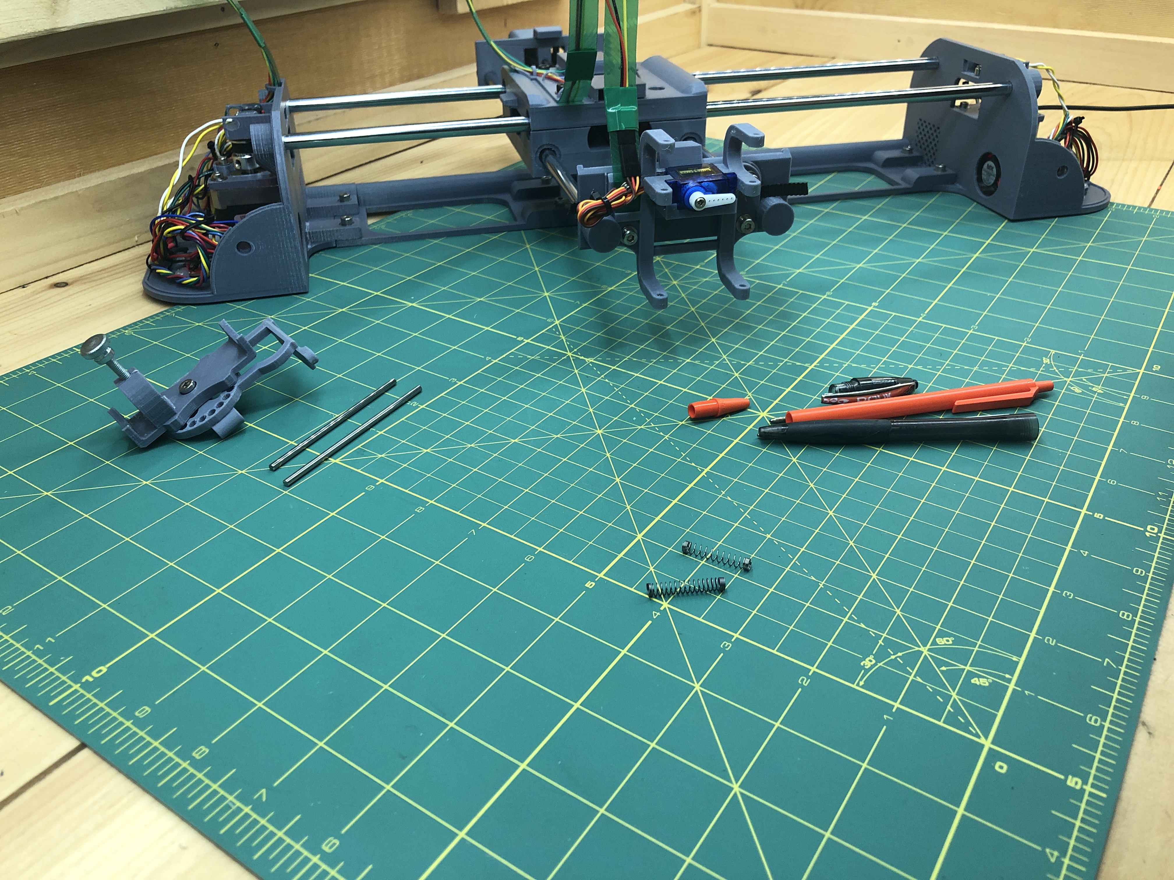
Then attach the pen holder to the plotter one rod at a time, placing the springs strategically. You might need to adjust the springs by forcing them to a new length.
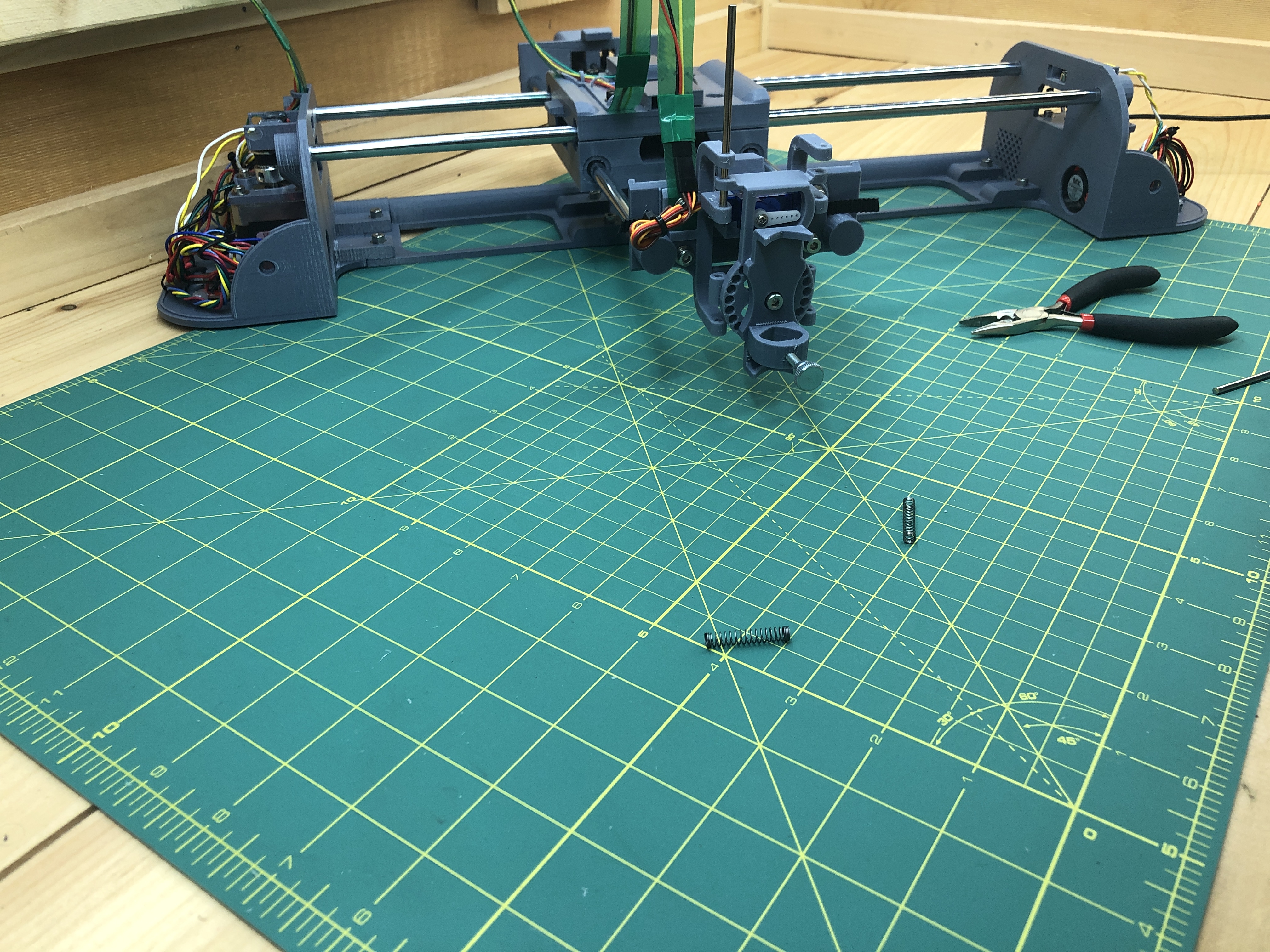
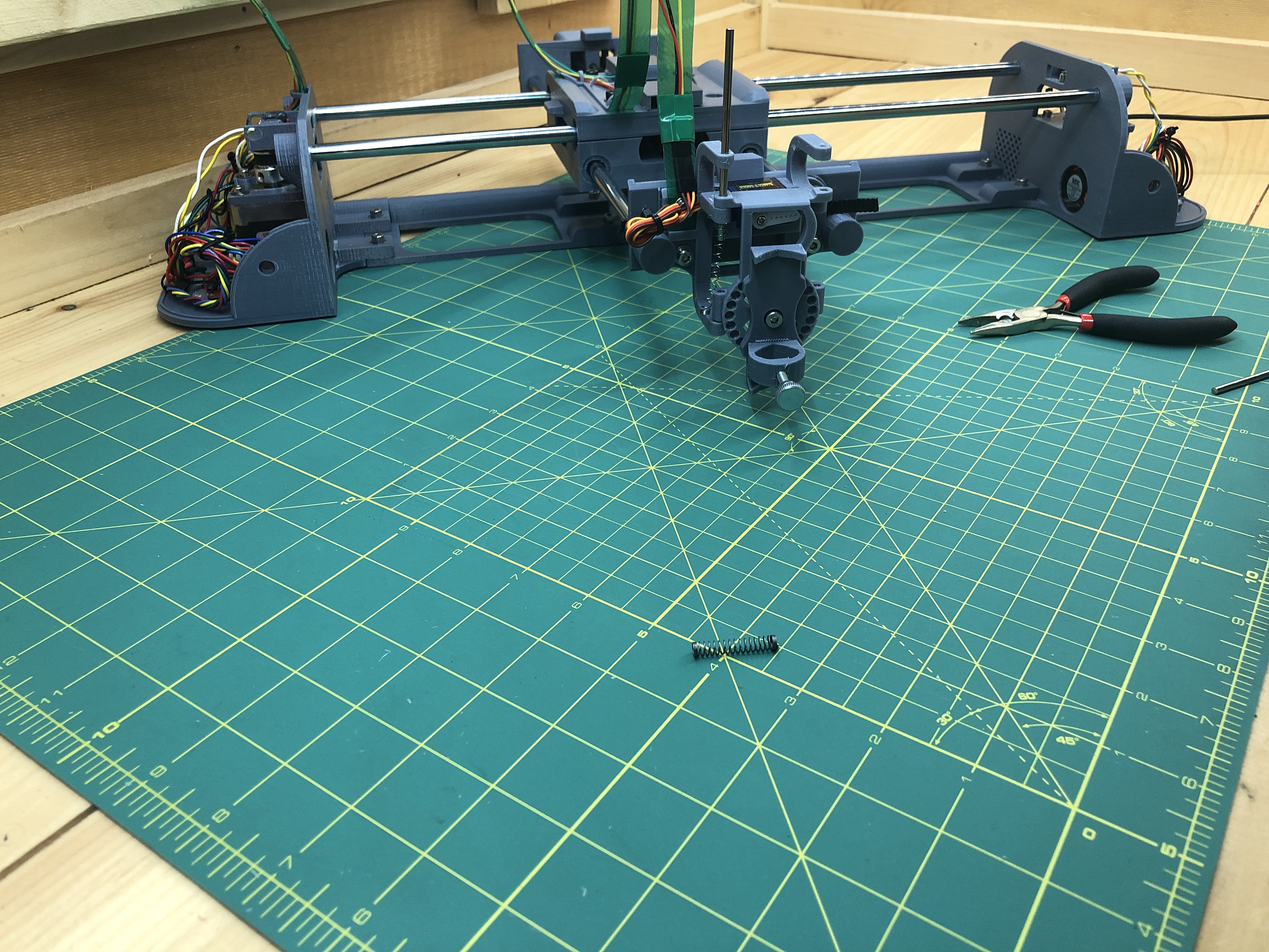
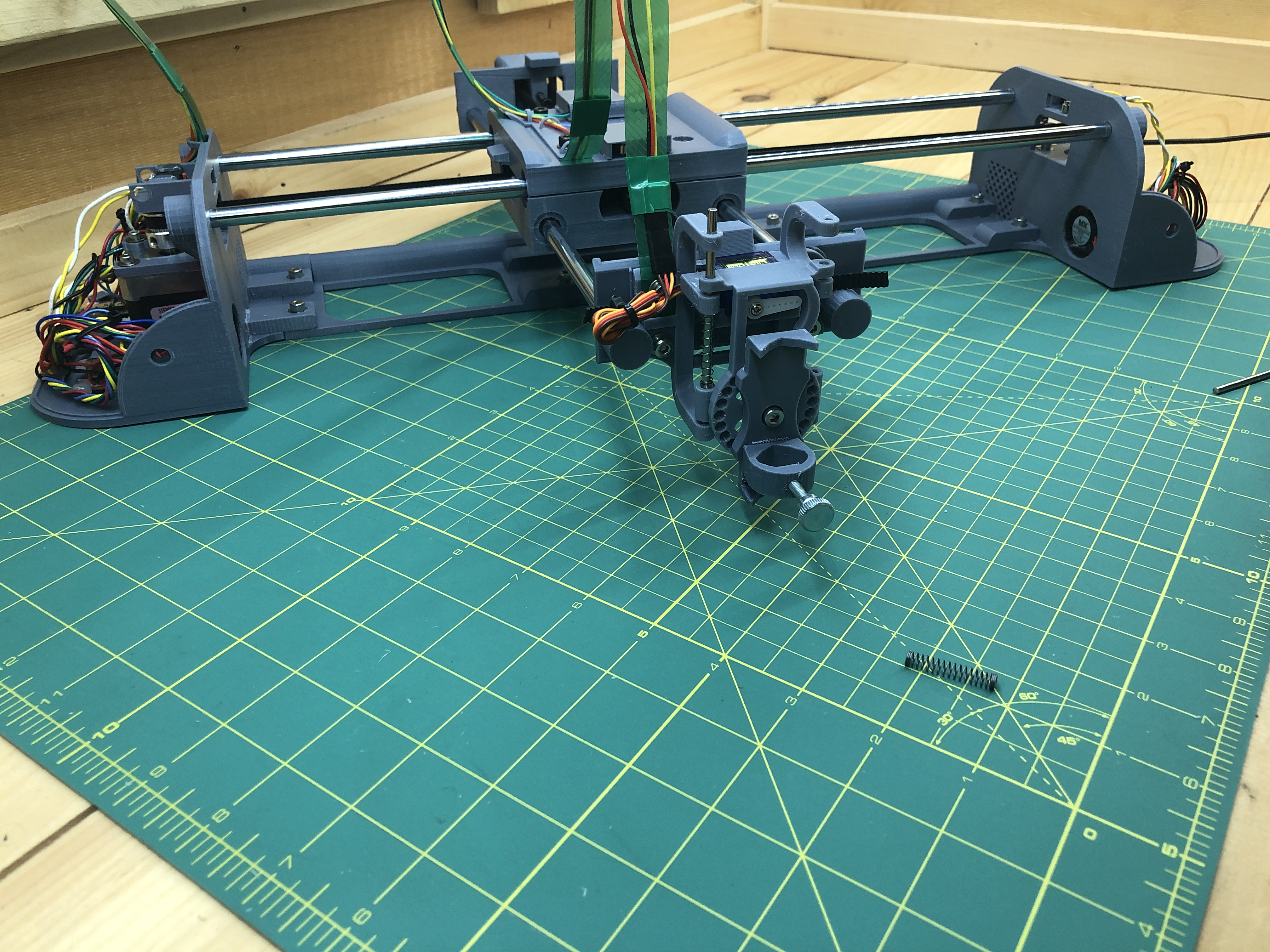
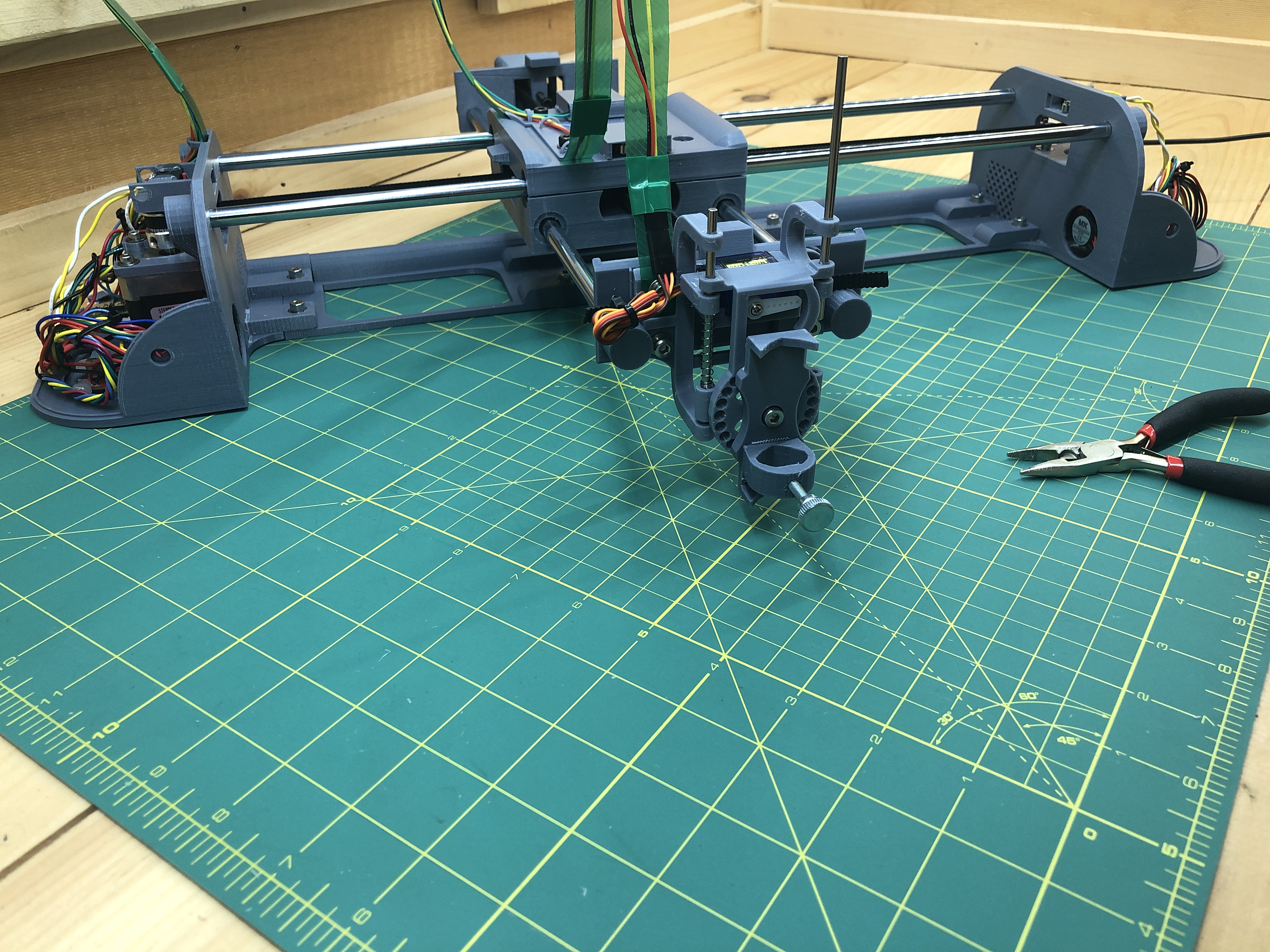
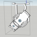
Of course now is the time to try our “Pen Up” and “Pen Down” buttons in the Mechanics section of the web interface.
Success!
11. Final steps
Hardware:
4 M4x8 hex screws
4 M4 nuts
14 rubber feet
3D Printed:
terminal_top_cover_x1
terminal_bottom_cover_x1
Electrical:
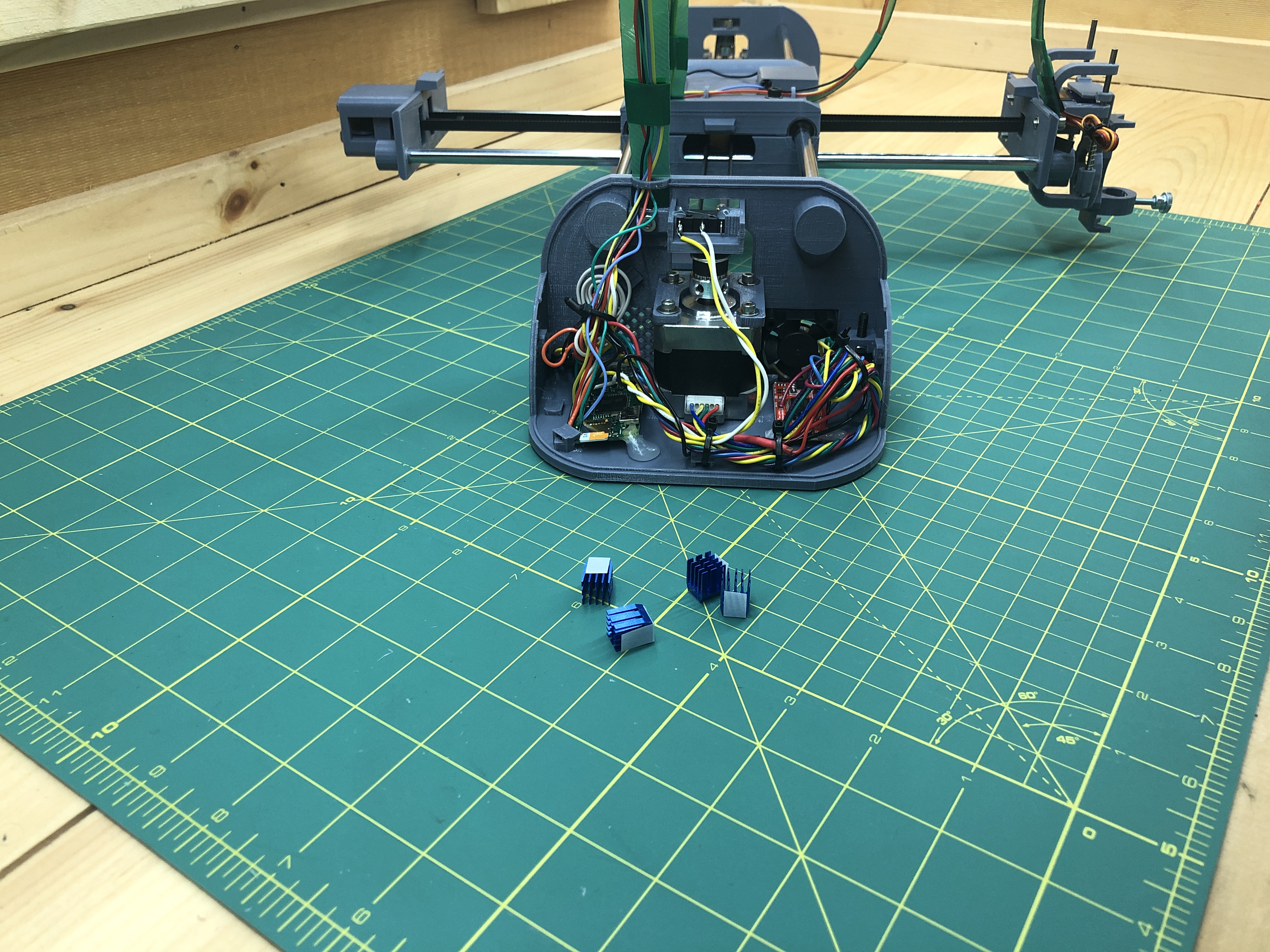
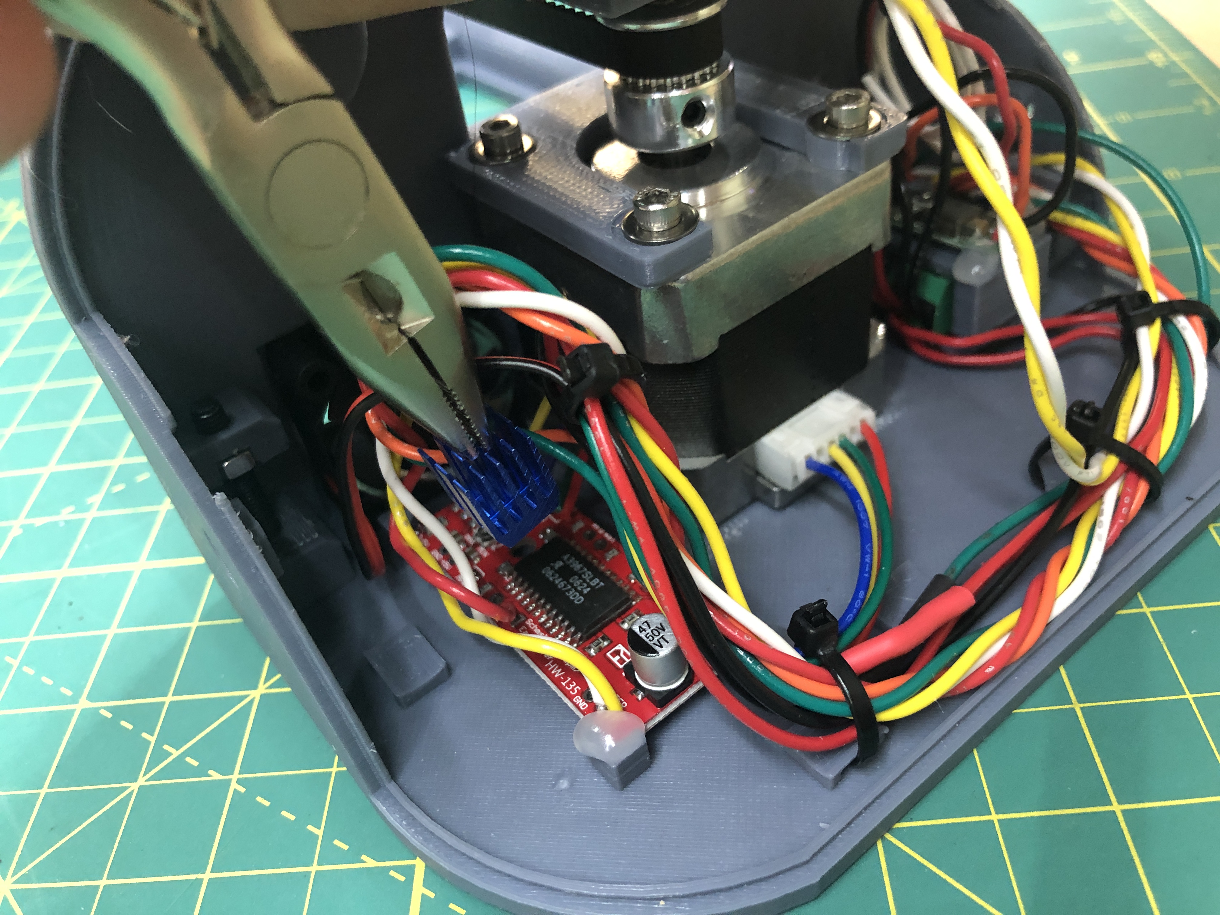
4 heatsinks
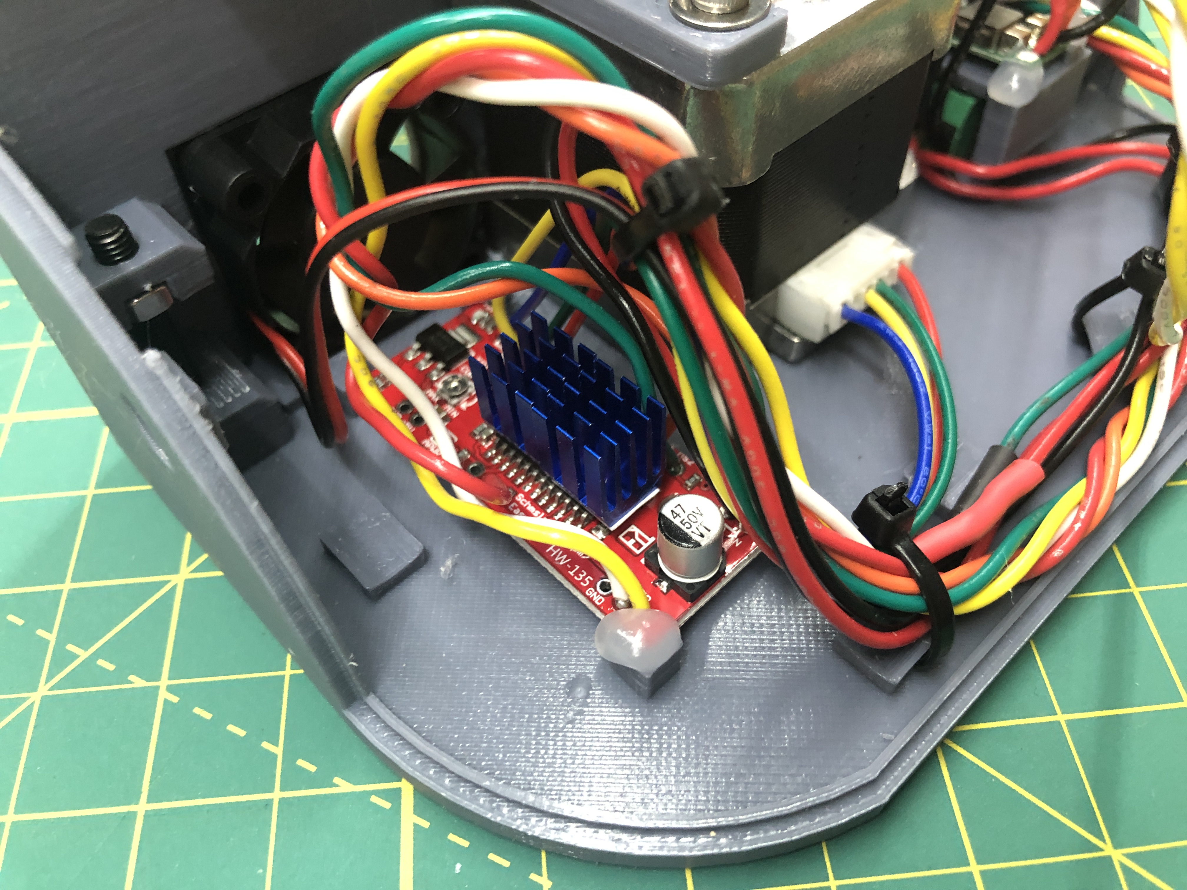
Our stepper drivers can produce a lot of heat, on top of being next to a fan, we’ll give them heat sinks. They just stick to the chip and it takes 2 to cover 1 chip. Do this for both terminal’s stepper drivers.
Grab your terminal covers.
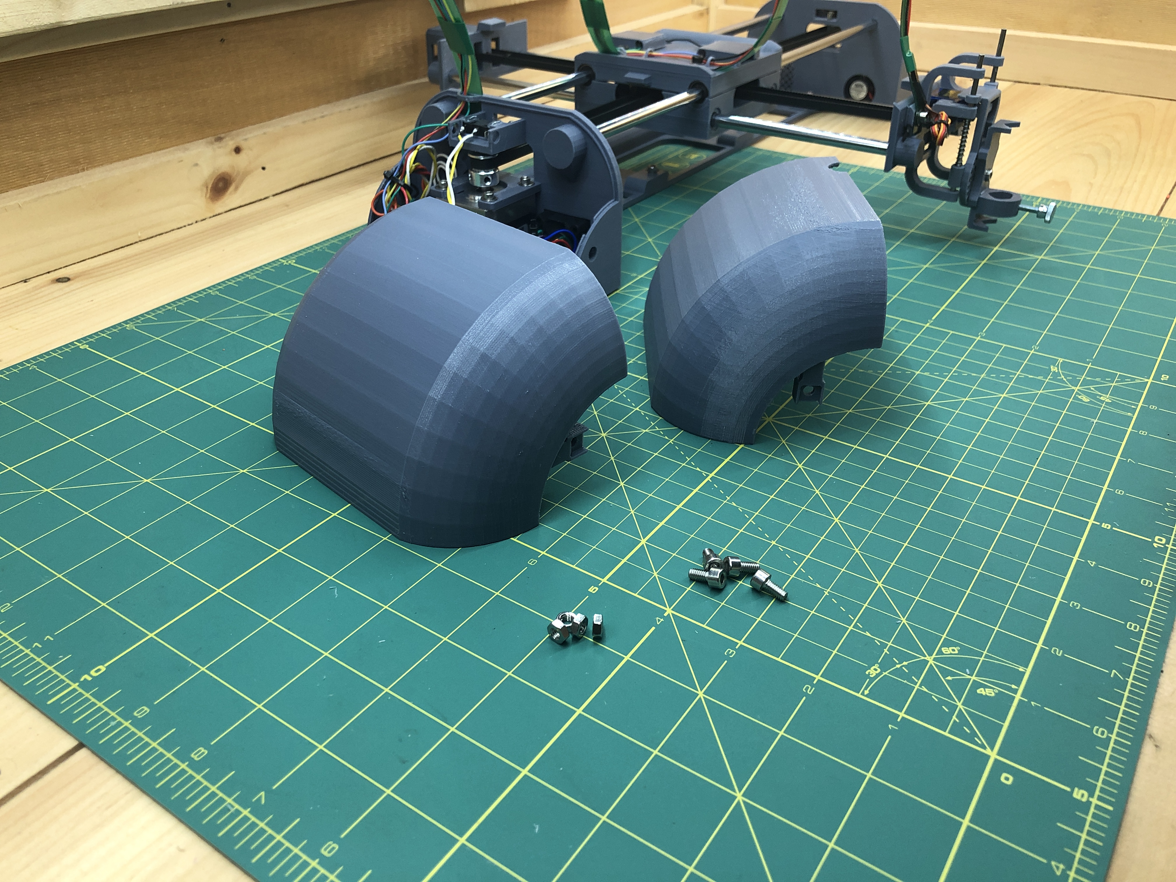
Pressure fit 4 M4 nuts in each of their little protruding arms.
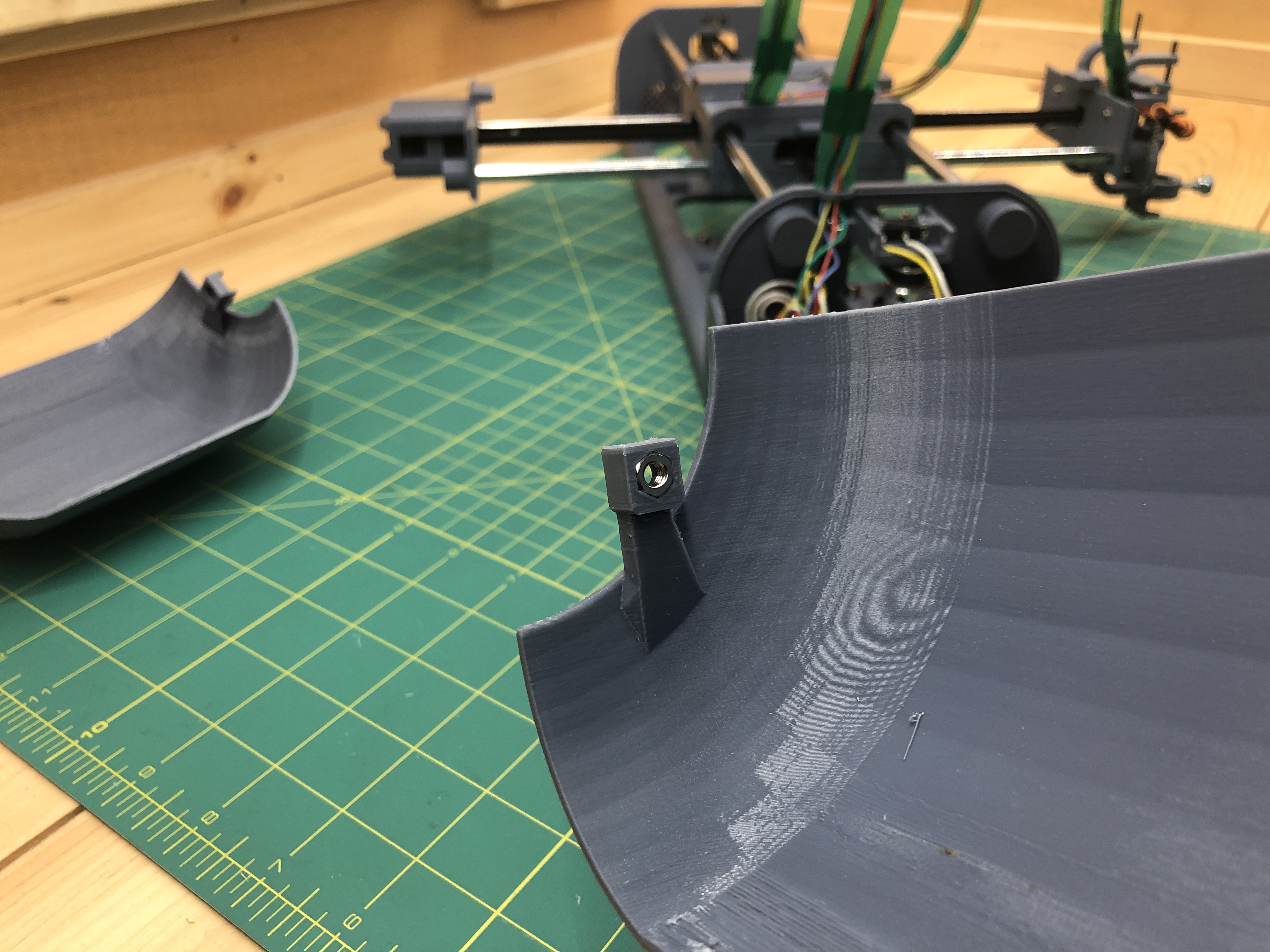
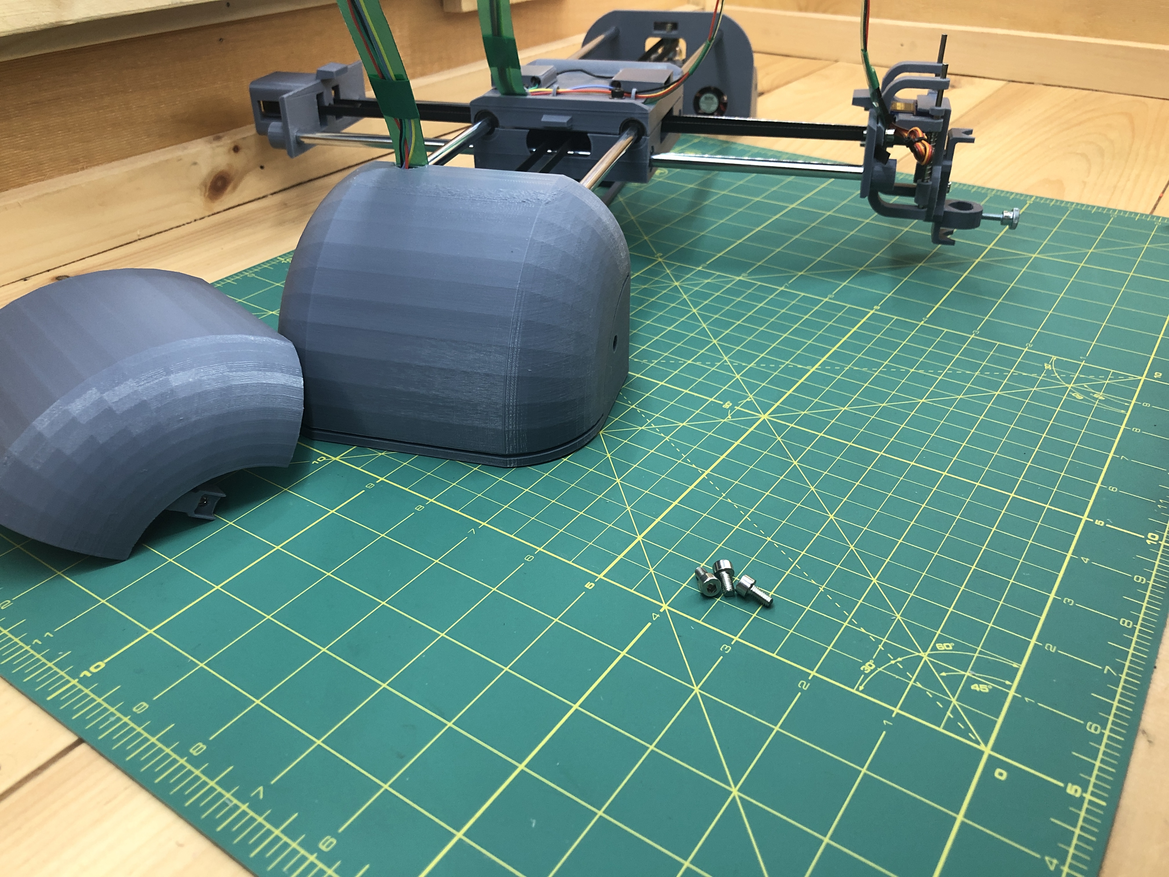
Wiggle them in place on top of their respective terminals and screw in the M4x8 hex screws to the side. Getting them in place is a bit of an art, you want to make sure that the little arms embrace their matching shape in the terminal.
Finally, flip your plotter over and stick 14 rubber feet where there are receptacles for them.
Voila!
Head over to the web interface and try a simple plot to make sure everything is functioning correctly.
As an afterword to this extremely long instruction set, I would like to congratulate you for your patience and tenacity. I refined this plotter over years and many, many prototypes. I tried very hard to provide instructions which were as clear as possible while making no assumption of understanding of any kind. It contains all the tidbits of missing information I had to find the hard way when I was researching how to build such a thing. I hope to have made this project free of the blind spots and dark corners I found myself into. Equally I hope for the software stack to significantly lowers the bar of entry to just get a plot going. If you find anything missing or unclear, please do reach out with a comment or email and I’ll fix it. May your new toy scratch your plotting itch :).
Please do get in touch if you build this, whether or not you are having issues. Thank you and take care!
Use Instructions
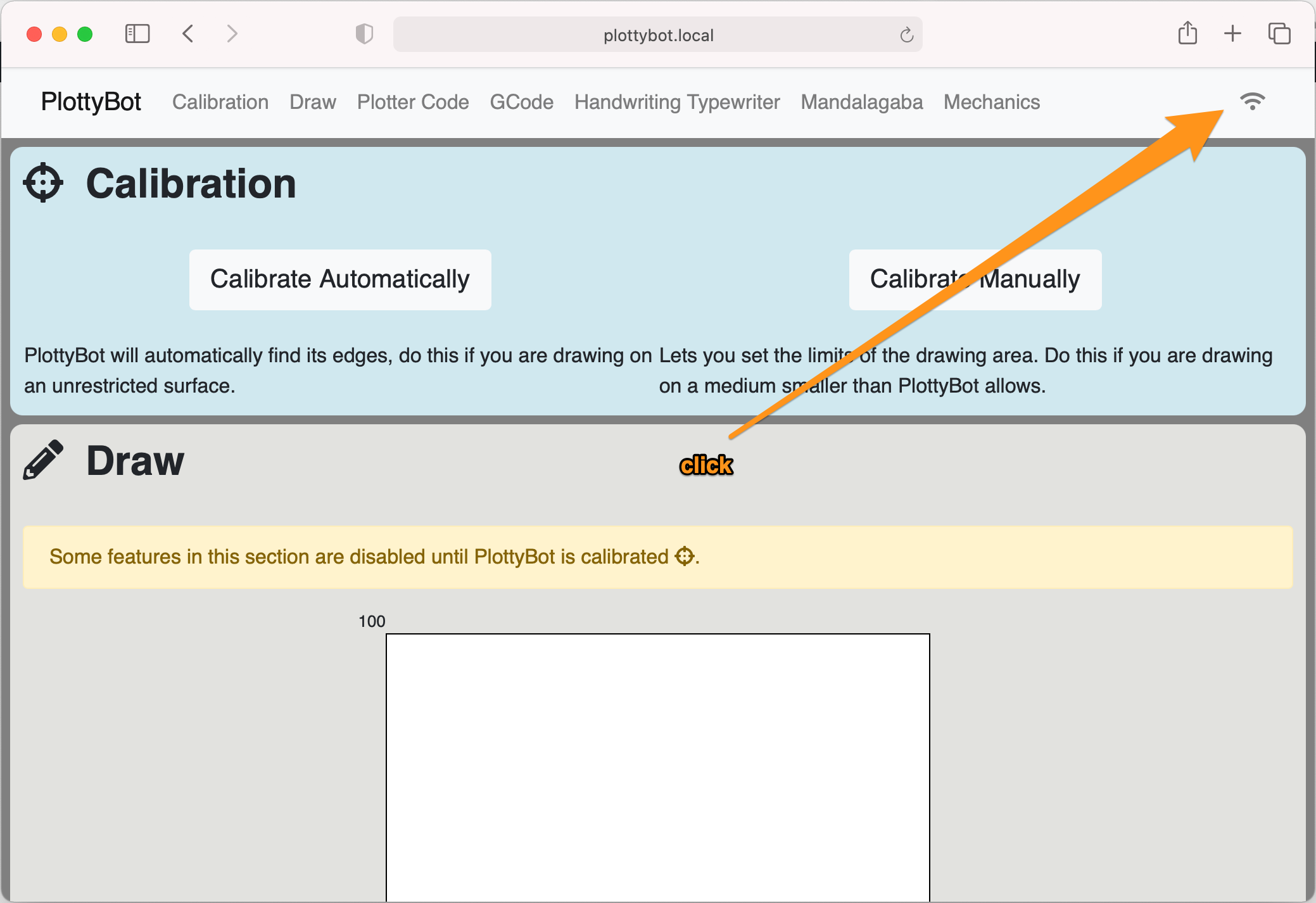
Connecting to Managed wifi
To avoid having to point your computer to PlottyBot’s wifi for use, which disconnects you from the internet, you can instead point PlottyBot to your home wifi and have it connect to your usual network when it boots. If you boot it outside of your home wifi’s range, it will still span its ah-hoc network so you can always connect to it.
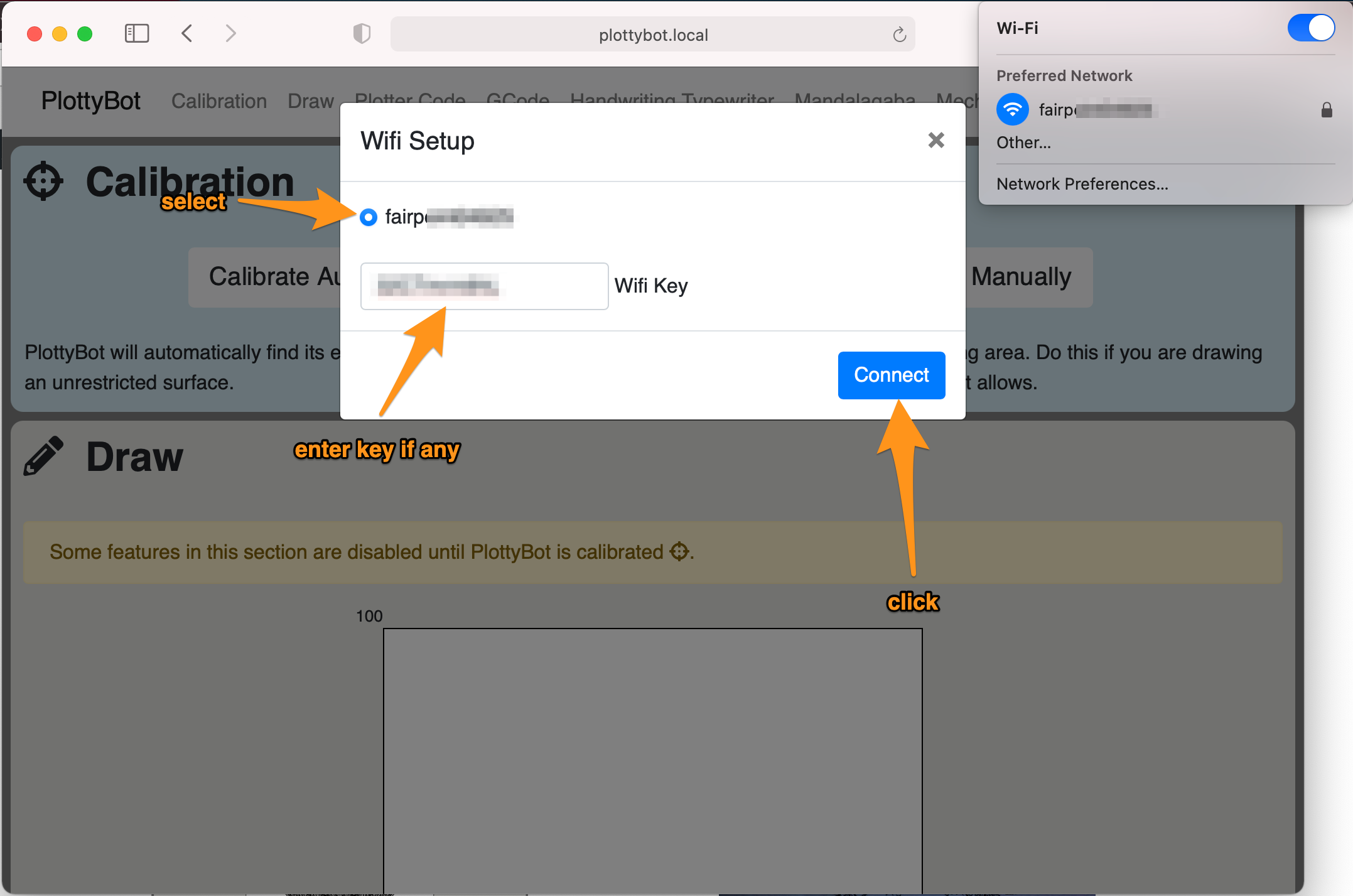
After your plotter is connected to your network, it can still be accessed via http://plottybot.local or http://10.0.0.5.
This feature isn’t well tested. It works at least on WEP & WPA2 networks.
That’s it?
A lot more could be said on how to use the plotter. I hope that a lot of it is intuitive enough. If not Dave Evans has contributed a very nice Getting Started document. Thank you Dave!
FAQ
- What’s up with the sound the plotter makes? The stepper motors have inconsistent pitches when moving straight.
This is the result of 2 phenomenons, the first is that there is an acceleration algorithm in effect. The second and most likely culprit is that the sleep time is enacted by Python in software land. Python on a Raspberry Pi does not have access to dedicated hardware to “sleep” (wait) between stepper motor steps in a way that is accurate at the millisecond resolution. Python is competing for CPU cycles with other processes on the Pi. What this means is that the “attention” Python gets from the Pi is not dedicated and so the sleep time between steps may vary a little in a way that you’ll hear. Equally true is that sleep times are a minimum, if you instruct Python to sleep for 0.01 millisecond, it will sleep at least 0.01 milliseconds, and so while you can count on Python on a Pi to not sleep so little as to break the mechanical limits of how fast a stepper motor can move, you can’t count on it not sleeping a little more which is something you’ll hear. This is a draw back of working with stepper motors on a Pi, but the other processes getting attention make the Pi a very desirable device to step motors on regardless. An Arduino could not step motors while being connected to WiFi and serving web pages. At the end of the day, all your stepper motors do is sound a little funny in exchanged for a fully fledged software stack.
- Why is the plotter so slow?
The software comes with default settings for the motors which are optimized for reliability, not speed. This is especially true as each build introduces variation (belt tension, bearing smoothness, et cetera). Once your plotter is working and you want to make it snappier, head over the the “mechanics” section. Here you can tweak these settings, I recommend looking at the settings for the pen up & down action first, limiting travel and delays on this action will have a drastic impact on the overall longevity of a plot.
- What are the maximum plotting dimensions?
The base build documented here can plot up to 324mm X 225mm. Please note that these are the limits of the ideal 3D model and you are likely to shave a few millimeters off the ends where the limit switch should trigger before the gondola actually makes contact with the terminals.
- Can we change the plotting dimensions?
Yes, within reason.
The X axis can be changed simply by using longer rods all parts are the same you’ll just need more belt length. But this axis is not supported on both ends and so the further your reach out the more likely you will run into balance issues. I built a bigger model with 450mm rods on the X axis and it performs fine.
As for the Y axis, it is supported on both ends and can likely be made much longer, but when you do so you need to make the slab part longer. Here is a link to an elongated slab to support 600mm rods on the Y axis. If you need a different length and can’t work with the STL let me know in the comments.
Future Features & improvements
- cover model isn’t perfectly flat at the bottom (printing problem)
- make gondola bottom holes bigger to grab on the lock nuts
- does Python sleep better with nice?
- DHCP server doesn’t turn off when joining managed network (at leat on Pi Zero 2) see comments
- interference from DC cooling fans?
- need a way to report back stderr
- manual calibration an issue on ipads because of JS events listened to (mousedown vs finger actions)
- Consistent approach routine to homogenize belt tension at destination coordinates
- SVG to GCode converter with optional hatching
- Gondola Plotter support
- Laser engraving implement
- Time estimation
- Load Google fonts locally when not connected to the internet
- Support open & wep networks
- When connecting to managed wifi, be more graceful about refreshing page and having some sort of acknowledgement and waiting animation
- Build for latest Rapios
Very nice project, and a lot of fun.
I have just finished mine. The motors and limit switches were probably the most frustrating, but since not all motors are created equally, I just had to diagram out the wiring. I had 1st and 2nd coils initially flipped, so my limit switches were acting as if I had them backwards, but I got that figured out.
I did have some confusion with the software, as it didn’t appear to accept some gcode standards, but I was able to use your example gcode in one of the comments above, and get a parser written to convert raw gcode from Drawbot to the something acceptable for PlottyBot. I then pulled the /var/www/html folder off the pi and plottybot.py and was able to get it modified to accept direct, standardized gcode. I rebuilt the Dashboard – it contains the calibration section, paper size calibration, (plotter units to mm) with paper size selections and scaling.
It uses a similiar style for GCode insert, with option to load from file and paper orientation for portrait or landscape. I added project storage for plots with multi-pen – multiple gcode files. One thing that I could not figure out on the original software, was that no full gcode would ever finish – I suspect due to the size, maybe out of memory or even my gcode parser causing problems. It seemed random every time.
I’m no longer having that issue, at least not for a few runs. I put the MandalaGaba back in but have not thoroughly tested it. Most of the dashboard is new with a couple of re-used assets, but the plottybot.py is still used on the backend with modifications. Would you be open to me throwing this on github?
Wow, it’s been a while since I heard of someone building one 🙂 Nice. And amazing that you’ve gone this far improving the software stack. I’d love to see the changes you’ve made, you’re welcome to do whatever you’d like with the code, I don’t put things online with strings attached.
I’ve actually been improving the software stack significantly these past few months, mostly to port it to all the other drawing machines I’ve been, but it inevitably led to improvements in other dimensions, including some you did yourself, and I’m pretty sure I tackled several size issues too as I threw larger and larger files at it. None published so far as I’m still working on this. You’re right that my GCode parsing is asinine. I got turned off by the various flavors so I’m parsing for known markers without much regard for the actual GCode standards. I initially developed for Inkscape’s flavor of GCode, and then adopted a few other I found in the wild, or that others brought up.
There is at least one other group I can think of using this in education who would be interested in improvements. Would you like to hop on a call some time to compare notes?
Absolutely! I’ll drop you a direct email. I’m pretty tickled with the results I’ve gotten so far – This is the first attempt at a multi pen drawing if the link works,
https://photos.app.goo.gl/vuiicvMMXZD1iS1e8
and this is the Dashboard,
https://photos.app.goo.gl/dnsKnGmjvtw1GekXA
I’m still dealing with some bug fixes, but it’s been pretty functional.
Hi Ben,
Not even sure this reaches you, but thinking that if you run this on your small device, chances are you are still around.
I’m rebuilding the plottybot since the first time i had a crap 3d printer and everything was misaligning. It has been so long ago it’s hard to follow the circuit diagram.
Would you share the fritzing file, so i can figure out which wires (of same color) go over each other and which should be merged?
I would appreciate it immensely.
Oh I’m around all right :).
here you go: http://ben.akrin.com/downloads/plottybot.fzz
Many thanks Ben
First, this is an awesome project, thank you for your effort and generosity.
I’m done printing parts and am working through the list, preparing to order items. The part ‘belt, stepper gear, lm8uu’ (https://www.amazon.com/KINGPRINT-Printer-Reprap-Bearing-Coupler/dp/B07BMNDDDL) is no longer available, is there an alternate you might recommend? Or individual parts vs a kit?
These Amazon listings are a lot more dynamic than I anticipated sorry. This kit was nice and cheap, but really all you need from it is 8 LM8UU Linear Bearing, a good length of G2 timing belt, and the 20T Timing Pulley that goes on the steppers. These are all *very* standard in the world of 3D printing and very easy to find a bazillion other listing for, in kits or individually.
Thanks so much for your reply. Although I’ve been 3D printing for a few years now, I’m still new to the DIY side of things and familiarizing myself with the components. That’s why this project is so exciting, a huge opportunity to learn and overcome challenges.
Hello, where can you download the SD card? The download link seems not to be working.
I fixed the link, sorry about that. WordPress gets a little finicky when editing such a large page :).
Hi again, I’m still hacking into things and I think I’ve found a bug in the calibration routine. One of my dimensions was always 100mm and it’s coming from the block starting on line 1306.
Does markdown work here?
“`python
if canvas_max_y_steps>canvas_max_x_steps:
canvas_max_x = 100.0
canvas_max_y = 100.0*(float(canvas_max_y_steps)/float(canvas_max_x_steps))
elif canvas_max_x_steps>canvas_max_y_steps:
canvas_max_y = 100.0
canvas_max_x = 100.0*(float(canvas_max_x_steps)/float(canvas_max_y_steps))
else:
canvas_max_x = 100.0
canvas_max_y = 100.0
“`
I’m not sure why the max dimensions should be coupled like that; X and Y dimensions are independent of each other, and why set one to a static value of 100? Also max_ should be a function of `steps_per_cm`, right? I’ve changed mine to this (I don’t think the gondola param is supposed to be used in a tabletop setup based on what I’ve seen in the code but it makes sense mathematically):
“`python
canvas_max_y = canvas_max_y_steps / gondola_steps_per_cm * 10 # x10 to get mm
canvas_max_x = canvas_max_x_steps / gondola_steps_per_cm * 10
“`
and when calibrating on a page of known size it matches my expectations.
Scott, I don’t believe it’s a bug, but it’s definitely a funny decision, and it likely arose from historical code when I was deving early prototypes. What’s going on here is that I want the plotter to always have 100 units. It’s arbitrary, but you could have a big plotter, or a small one, or a gondola plotter and they’d all have 100 units to address. It makes it easier to conceptualize as a human (and to explain to others, I do teach with these). Now of course, more often than not, the plotter was calibrated in the shape of a rectangle, and so I’m setting one dimension to 100 and computing the ratio using the steps for what the other dimension should be. The steps aren’t related to the units you get, they only serve to give you a ratio for an arbitrary unit that really likes 100. As soon as you calibrate, this should be reflected on the web interface and the units will update to what was computed (and the shape of the drawing area will change).
I’m not sure what would happen if you set canvas_max_x and canvas_max_y the way you are. It might just work, but you may have other issues. For example the code I wrote to convert GCode to PCode might have an assumption of 100. Maybe not, I don’t remember off the top of my head.
Thank you for digging in and reporting this. It’s worth mentioning I will soon go through all this code and refactor it some. I’ve been in touch with an organization that’s using PlottyBot in education and it’s made me want to spiffy up this code some. That and I have a couple of other projects that will likely use the same stack so it’s worth the effort :).
Sorry for my late response.
Interesting, so the values don’t necessarily map to real world measurements but in plotter-space you have a normalized distance to use as the reference. That makes sense and definitely not a bug, just a bad assumption on my part. Maybe the solution is to tweak the UI to indicate “hey these numbers aren’t mm”.
The issue I was hitting that lead me to look into it was that my text/image–>SVG–>pcode pipeline includes actual physical dimensions of the resulting SVG, and when I dropped the pcode into the UI the resulting text/image wouldn’t be scaled properly, or at least it didn’t appear to be scaled properly. If I converted a 100mm x 100mm image to pcode I wouldn’t necessarily get a 100mm x 100mm image back out and now I see why: 1mm != 1 plotter unit.
For my own sanity I needed to map real world coordinates to robot coords, and with my patch in place the plotter units displayed in the UI after calibration match the real world dimensions of my work surface. Granted, I haven’t exercised every code path so it’s entirely likely that I’ve broken something somewhere else, but so far it’s working exactly as I would expect.
What is the coordinate frame of the robot? When I’m calibrating manually what are the leftmost and lower edges? The down arrow moves the gondola toward the end with the Pi; is this the lower edge? Left arrow moves the pen head closer to the gondola; is that leftmost?
That’s exactly right.
Posting for posterity and general awareness, there’s a very straightforward way to convert images to plotter code. Download the free version of https://github.com/SonarSonic/DrawingBotV3/tree/master, convert your image to paths and disable all colors except for the darkest. Click on File–>Export per drawing–>gcode. Open the gcode and replace all instances of “G0 Z1” with “(Start cutting path id: )” and instances of “G1 Z0” with “(End cutting path id: )”. Paste the gcode into the interface and you’ll get working plotter code. I’m sure you can get fancier with it but this is incredibly easy and works well for basic images.
those are backwards, should be G0 Z1 –> end and G1 Z0 –> start. Also the user’s python script below that converts gcode directly to pcode is a good way to do this outside of the UI for more control.
Thank you so much for such a detailed project! I’ve just finished building it and everything worked beautifully from the start. The interface is so well done, really good work. I was wondering if the code is on github anywhere; I searched around but didn’t see it, wanted to ask before I go digging around in the Pi image.
I’m afraid you’ll have to dig through the Pi image 🙂 feel free to ask for pointers though. Thank you for the nice words, I always like to hear from people who built one.
I’ve already found everything in the image. Sneaky, it took me a minute since I didn’t see any systemd services, and I like your trick for applying the first boot script, going to file that one away. First order of business is to add a shut down button to the UI, odds are low that the SD card gets corrupted but I’d feel better with a proper shut down instead of yanking the power. I was also curious to see how you handled comms between the front end and back end and was happy to see sockets.
Nice yeah good old rc.local :), nothing sneaky about it really. I’ve gone through several iterations of process initing through the years and rarely have the need to figure out anything other than old reliable rc.local. As for the SD card, I really wouldn’t worry about shut down, the corrupted filesystem fear is one of an ancient era of computing, ext4 is crash consistent, and most of all from experience I have never ever ever ever lost a partition this way. And if I’m proven wrong, it’s not like it keeps important data either. It’s a nice way to get familiar with the code base if that’s what you’re after.
Yes, I do want to dig into the code, especially the front end because that’s where this really shines and it’s a serious weak point for me. I found the gcode_to_turle and draw_turtle_code JS earlier; does the plotter fundamentally parse turtle code to move? I’m already imaging a CLI tool to send an SVG in and have it parse the path and send commands to the plotter over a socket.
Unrelated, but I couldn’t find any plastic suitable for the wire carriers but found that printing strips of PLA 13mm x 200mm x 1mm gave me enough flex to work with. I welded a couple of those together for each axis and trimmed to suit and so far it’s working great.
You’re right it does parse “turtle code” fundamentally, I realized my naming mistake later, it’s not exactly turtle code so sometimes you might see it referred to as “plotter code” or pcode. It’s very much like GCcode just a bit simpler, it’s all fairly simple X,Y coordinates instructions at the end of the day.
Thank you for sharing your trick for making your own flexible plastic, I love it!
Ok my next question was going to be what pcode was, because I was pretty certain that it’s not an intermediate code between assembly and a more abstracted language, and that’s what the internet was telling me 🙂
Last question for now: What flavor of gcode does it speak? I found your sample below and some of the commands aren’t familiar, particularly the `df` preceding the `G0` commands.
No particular flavor, I just read it as a series of X,Y coordinates. Sometimes it’s an issue to map depth to a binary pen up/down, but I adjust whenever some program I’m using spits out GCode that’s different.
I see. I noticed it fails to parse unless I include the (Start cutting path id: ) and (End cutting path id: ) lines, or at least appeared to fail. Other than that the SVG–>gcode–>pcode pipeline seems like it will be pretty straightforward.
Yeah it’s pretty terrible 🙂 that’s what Inkscape spits out at least. It supports a couple of other GCode “formats” I stumbled upon that don’t have the “Start cutting path id” syntax. I’m honestly not sure if there is an official GCode syntax documented anywhere, what I found was a bit of a mishmash and I didn’t have time to launch into a GCode rabbit hole. If you’ve got a format that doesn’t work for you, feel free to send a sample and I can adjust to account for it.
Have we reached max nesting of replies? I can’t reply to your latest message. Anyway, Inkscape explains those weird line beginnings and endings. Re: gcode there’s no “official” version that I know of, but the Marlin index is what I use as a reference. https://marlinfw.org/meta/gcode/
Hi again. Sorry it’s more questions from me…
The PlottyBot has started to do something odd. There are a couple of photos here where you can see what’s happened: https://imgur.com/a/S3G9wdr
In each case, there was an instruction to draw from bottom left corner to top left corner. The pen steadily moved in the y direction as it was travelling so the drawing of all four corners is not rectangular. PlottyBot thinks the top left corner is further to the y than the bottom left corner.
Where should I start looking for the cause?
And something I’ve been meaning to do for ages – I’ve put into Google Drive a pdf of “PlottyBotting for Beginners” so users won’t need to find an md viewer. It’s in the shared folder.
Hey there!
well that’s just completely bizarre 🙂 it looks like a software error but I can’t even begin to theorize about what it could be at the moment.
Do you have the “Plotter Code” that you had it run? I might run into the same issue with my machine. Maybe there’s something about it.
How did you do the calibration? Manually or automatically?
When you say it started doing that, did you run that same code previously and it made a proper rectangle?
Sorry I only have more questions to offer at the moment
And thank you very much for the PDF, I’ve updated the link to point to it.
Gday Ben, thanks for the reply. I’ve added another couple of pics on imgur (same link), the result of the following:
1. Flash a new SD card with plottybot_2021-04-22.img
2. Access PlottyBot over the home wifi and choose manual calibration
3. Set the four sides at roughly the edges of an A4 sheet taped to the bench
4. In pen calibration choose “go to top left”, pen down, then each of the following corners to make a (not!) square
5. Choose pen up
I can see that the top left corner is lower on the page and further to the right than where I set it to be, the lower left corner is where I set it, the two right corners are as expected, and that PlottyBot has successfully gone from bottom left to top left with a straight but slanted line.
As far as I can recall this used to work as expected, but I don’t have any photos to confirm that. If another user follows those same steps, with the same .img, the answer should leap out – hopefully 😉
Next I opened a Mandalagaba session, PlottyBot remaining on with the same calibration. I doodled and got the fourth picture in imgur. The drawing top is about where my top edge was set, and as far as I can tell with my tape measure the drawing has come out square and not distorted.
The “square” in the first picture on imgur showed writing from your handwriting interface, but the frame was drawn afterwards with the manual calibrator doing what I outlined above.
Which all makes me think any issue might lie only in the pen calibration – unless it’s a hardware thing on my build (all too likely, I fear).
I hope that all makes sense, but if you need anything more I’ll do my best to provide it.
Just in case you’re up for a bit of updating: While flashing the new SD card I discovered that Pi Imager now allows users to provide wifi credentials for insertion into the OS image so nobody need attach a monitor and keyboard to the Pi Zero. That was a huge relief to me – every time I’ve disturbed the Pi in PlottyBot, at least one of my soldered connections has come adrift!
Update: No real issue! Here’s what’s happening.
I entered this plotter code to draw a square using the calibration integers from the “Draw” space:
pen_up()
go_to(0,117)
pen_down()
go_to(100,117)
go_to(100,0)
go_to(0,0)
go_to(0,117)
pen_up()
That drew the expected square.
Then PlottyBot moved the pen to the parking spot – which is the same spot as the top left corner of the not-square in the pictures.
So it seems that somewhere along the way, the pen calibration button “top left” actually goes to the parking spot, not the calibrated top left. Everything else continues to work properly – whew!!
Ok ok! I got it :). Sorry it took me so long. You’re totally right that the calibration corners aren’t perfectly lined up. But this isn’t an actual calibration issue and the machine works perfectly. I guess I never really thought that someone would actually draw the square when sending the pen in all 4 corners, I saw this more as a way to adjust the height of the pen in various locations. In fact when going to the corners, the plotter doesn’t go to the actual extremes, it adds some margin so you have a bit of room. So the corners don’t actually serve to reflect extreme positions, it really is just about pen height in a sample of key locations. And so, a while back, I did have a bug where some corners would have the margin and some would not. That is the issue you are seeing. It’s wrong and it’s confusing, I did in fact fix it a few months ago, but I too am running an older image on my go to plotter so I’m seeing the same issue. I’m updating the download links with a version that *I think* has the fix in, if you care to, you can download it again. But really, this isn’t a bug that will affect any actual drawing that the machine will do.
I am aware the the Raspberry Pi imager now lets you bake in settings which is very useful. For the PlottyBot image though, it should span its own Wifi when it isn’t connected to anything, so you can always connect to it without having to plug it into a monitor. From there you can scan for other Wifi networks such as your home wifi and connect to it. You don’t have to, it’s just a bit easier than being connected to the machine direct since it doesn’t route to the internet.
Thank you for your mentioning this new capability, and the bug you found. It’s not critical and it should be updated in the newest release (or it will be in a new new one :)).
Hi Ben!
Thank you for creating this great project. I’m finally starting with my build and I’m really excited about it.
Some parts are unavailable at the moment, I tried to find proper replacements – would you mind to take a look at them?
1. The stepper motor driver:
https://botland.store/stepper-motor-drivers/2660-stepper-motor-driver-a4988-reprap-red-5904422359201.html
It looks like can handle 12v and has the same features in this voltage:
https://unorthodox-engineers.blogspot.com/2013/11/review-more-arduino-motor-modules-a3967.html#:~:text=That's%20really%20the%20principal%20difference,overheat%20when%20you%20go%20above.
I am aware there will be some issues with placing it due to dimensions differences.
2. The stepper motor – I found this replacement – do you think it will work? The torque and current are a bit lower
Steps per Revolution: 200
Step Angle: 1.8 degrees
Current per Coil: 1.7 A
Coil Resistance: 1.5 Ω
Winding Inductance: 2.8 mH
Rated Current: 1.5 A
Number of Wires: 4, bipolar
Holding Torque: 4.28 kg/cm
Body Length: 40 mm
Shaft Diameter: 5 mm
Shaft Length: 24 mm
Dimensions: 42x42x40 mm (excluding shaft)
Weight: 380 g
Thank you so much!
Pawel,
it’s impossible to know for sure without testing first but this looks reasonable. You could always dupont wire just one motor/driver from the circuit as a test to confirm.
Thanks for your quick response! I’ll give it a try and will post some feedback if it works 🙂
I think I put my response in the wrong part of the conversation tree 😉
It took some time to gather everything together, but I’m ready for soldering. Just one question – since A4988 driver (that I will use instead of the one used in the original project) has capability for 1/16 microstepping (MS3 pin) – is it possible to make the adjustment to utilize this feature or is it unnecessary/too complicated/whatever other reason for no-no?
If yes – where should I look up in the code to update it? 🙂
I don’t believe it’ll be necessary, as it stands, the plotter is wired for using the 2 microstepping pins but in hundreds of drawings, I never felt like a full step was too much so I never deviated from it.
There might be a very rare case where it’s useful to enable it some microstepping, but I can’t imagine needing 1/16.
In any case, take a look at /usr/local/bin/plottybot.py and search for “ms1” and “ms2”, or a variable called “step_size”, you’ll quickly find your way to the few spots where this is set. None of is is complicated so it should be easy to tweak.
Good luck!
Hi thank you for fixing the file,
i’m a fan of your project i see you have plans for svg on gcode
you wrote about some doubt,
this project is open source someone used it in blackstripes,
putting svg directly would be very cool
https://github.com/fullscreennl/blackstripes-drawbot-driver/tree/master https://github.com/memononen/nanosvg
sorry for my english i’m not good at this
I thought about having a way to upload an SVG directly into the web interface but it’s not ideal in many regards. Not all SVGs are created equal, some have overlapping shapes, some have fills, some don’t, some unioned shapes, some use color, some groups, et cetera. All of these things can be interpreted differently, and so you can’t have a one size fits all conversion on the drawing machine. I mean you could, but it would lead to unsatisfactory drawings in most of the cases.
In the world of CNC machining, the common language is GCode, and so I thought it’d make sense to let the user come with with GCode with whatever tool they want (there are many). SVGs aren’t even required as a step to GCode, there are tools that don’t use SVGs to get there.
I did accumulate a set of tools to turn SVGs into Gcode in a way that works for me, and each time I convert an SVG to GCode that the tools I use are a little different. While I don’t think it makes sense to have these tools right in the Plotter’s web interface because the process is different every time, I thought I might put some of them online at some point so they can at least be used. It’s also true that these tools tend to be resource hungry and would do terribly on a Pi Zero :).
Thank you for your suggestion.
Hi, how can i use “Dave Evans has contributed a very nice Getting Started document”
i have MarkDown browser but can’t find the file, You can send it to me
I fixed that link 🙂 sorry.
Hi Ben,
Congrats for that amazing project. I am on my way to built one.
Thanks for the kind words. You might be interested in the Gondola version which saw the light of day more recently. It’s easier to build and has the same software stack.
Hey Ben,
During the build time, you can realize how much hard work you have done throughout the project and walkthrough. Only if you try to make it you can realize that… Thanks a lot!
I would like to ask for your suggestions about something, I would like to sign some papers remotely, I can figure out the network part for the remote access but what way would you suggest if I wanted to sign on 3 particular areas on a A4 paper as a template and maybe having saved my signature somehow.
If I’m understanding correctly, the way I’d do this is to use an SVG editor, create a document in A4 and sign the areas you want. I’d save that SVG and convert it to GCode. Inkscape has a (terrible to use but very reliable) way to export an SVG in GCode. Then you can just paste that GCode in PlottyBot’s interface.
Thanks for your answer,
Is there any way I could edit the HTML page?
I forgot to mention that the signatures some time would be on different areas, so I would probably like to embed an RTSP camera stream on HTML and sign from iPad on real time. Does somebody have done this before?
I don’t think anybody’s done this before, but you can indeed change the page. SSH into the Pi with default Raspbian credentials and it’s all user /var/www/html.
Great, thanks a lot. I’ll make my tries and get back.
It wasn’t that easy as I expected.. I can manage to embed the camera string on the web ui, but real time drawing is not an easy job…
At the time I have mess with gcode convertion on macOS… there is no way to convert anything…
Hi Ben,
I just finished building my first Plottybot. First of all, thank you for making these amazing instructions that even I was able to follow. I had so much fun building this and it will be so helpful once I can get it to work.
I was hoping you or someone can help me with two issues I am having.
1. If any of the limit switches get activated it causes the whole thing to spaz out. I am assuming I swapped the servo wiring accidentally.
2. Only pen up and down commands are being executed and it skips “go to” commands. This is true both on my phone and PC. It does execute the ‘test bottom/top servo” in the “mechanics” section without any problems.
Thanks in advance!
-Avi
Hey Avi,
1. I’ve had this happen and it was in my case due to improper wiring. I can’t remember exactly but I want to say it was a ground pin solder that was touching another pin. You should be able to use the plotter regardless by using the manual calibration which does not rely on the limit switches. I use manual calibration all the time to exactly define the boundaries of the piece of paper I’m working on. That’s not to say you shouldn’t check your wiring 🙂 but you can do without if it turns into a headache.
2. the command is supposed to be “go_to( x, y )” not “go to( x, y )” (note the underscore). You should see a rendering of the drawing the machine is about to do, if you see that rendering and the machine doesn’t draw it, there’s a deep issue somewhere :). If you don’t see it, you need to adjust your PCode. Here’s an example for a simple square that should be a starting point:
go_to( 10, 10 )pen_down()
go_to( 10, 90 )
go_to( 90, 90 )
go_to( 90, 10 )
go_to( 10, 10 )
pen_up()
Does this help?
Hi Ben!
Thank you so much for the quick response!
I was using the manual calibration but I was mixing up the directions which caused it to skip all of the “go_to” and only read the pen up and down commands. It was frustrating but also a little bit funny. I found a gcode example that you sent in response to a previous comment and now that I have the calibration working, the plotter is working beautifully.
I think you are right about the wiring issue but since it is working now, I will leave it be.
I am still working out how to export lines from Rhino to a flavor of gcode that the plottybot is willing to use but I will figure it out.
Thanks again! I am a huge fan of everything you do and will continue to follow and be inspired.
I think I understand what happened with the manual calibration, thank you for describing it. It ended up with a canvas size of zero (or negative size), it ran the go_to commands but there was nowhere to be in zero space. That’s really good to know and clearly a lack of error checking on my part, I’ll improve
Could you please send me a sample of the GCode you are able to produce from Rhino? I very half-bakely threw a parser together and it’s really not up to par. I’m more than happy to make sure other flavors are supported. And this way you don’t need to worry about it :).
Thank you for the kind words.
At some point in the middle of the night, I figured that because I had wired the stepper motors in reverse I was manually setting the workspace to zero or negative. That can also explain the behavior of the limit switches. I think it is hitting a limit switch and telling itself to back up a bit but instead, because it is reversed, it is going right back into the limit switch and then it gets stuck in a loop and starts to dance. This sounds like what Alex B, the previous commentator described.
As for the gcode,
So far the plan was to export lines from rhino and then use Inkscape which according to other comments here seems to be the way to go. So far the gcode that it is exporting looks like this:
G01 F2100.0 X106.946 Y150.119; draw !!Xleft+106.946 Ybottom+150.119
That does not look like your example. I also tried a few svg to gcode online tools but none of them worked either.
Hi Ben, I’ve been a silent watcher on this project for the past 9 months or so, slowly gathering my parts etc. I’ve finally finished my build, quite exciting. However, I’m running into an issue that I’m not sure how to solve. When calibrating, either automatically or manually, the plotter moves to it’s top position, crashes into the limit switch and keeps going, grinding and slipping on the belt until I (hastily) remove power. I’ve tested the limit switches as per the instructions, I’m just not sure whats going wrong. Any help would be amazing. Cheers 🙂
Hey Alex, I’ve actually had this on one of my prototypes, let me see if I can remember the steps I went through :).
First of all, when calibrating manually, you are not supposed to run into the limit switches. This is meant to define boundaries smaller than the plotter allows. In fact I only ever use this mode of calibration because my sheets of paper are always smaller than the plotter. And so when you say that the problem also occurs with manual calibration, do you mean you hold the button all the way up to the limit switch? Or do you mean that there is a problem where the plotter keeps moving even when you release it, and then it bumps into the limit switch?
If it’s the former, I would say your next step is to actually do a manual calibration on some piece of paper, not running into the limit switch. And actually have it draw something. This will tell us that hopefully the plotter moves fine and it’s not a stepper motor issue, but really a limit switch one.
I want to say, that I had a limit switch with some contact with another wire/pin where it was soldered on the Pi, and that wreaked havoc on the circuit when it was triggered, resulting in erratic stepper motion.
I’m assuming, but maybe I shouldn’t so I’ll ask anyway, you are certain that the limit switch is getting triggered right? Is it possible that its tongue is too far in and actually not getting pushed all the way so the plotter keeps ramming into the terminal? As you launch the calibration you can trigger it by hand to see if it sends the plotter in the other direction or creates that same issue.
to recap, my recommendations are:
1. make sure the limit switch is getting pushed all the way and triggered by the plotter
2. try to calibrate manually without the limit switches, make sure motion is without issues on a drawing
3. check where limit switches are soldered and make sure there is no contact with other pins
I hope this helps.
Hi Ben, thanks so much for your speedy reply. I’ve done a little more investigating, but still yet to solve the issue. I have managed to get it to plot something which is very exciting!
So I’ve checked that the connections aren’t touching, I’ve used dupont connectors but heatshrinked the ends instead of using the plastic sleeves.
Today when I tried to manually calibrate it, it definitely moved by itself after clicking the button in the webUI. (It when to the top and jammed again). After this, I tried checking the switches again from the webUI, and noticed that this time when I manually pressed them, the plotter would move toward whichever switch was being pressed, constantly, while it was pressed. Not sure if this is intended behaviour? (I have a short video of this if it’s of interest)
I did also make sure the switches are being pressed by the gondola, there’s a few mm clearance at every end.
Lastly, and not sure if this helps, but I noticed that when using the buttons to jog the plotter, these are all reversed, I didn’t think much of it at first, however now I’m wondering if I’ve got the steppers wired in wrong or something? Although it did plot something correctly, so I’m not sure about that.
The other weird issue I ran into, is the box box doesn’t seem to like space characters? I checked the browser console, and see the a message being logged “TODO: should we replace the char with a space?” It can’t read the length property of ffont[next_unicode] it seems? I didn’t delve too deep into that.
Again I really appreciate your help with this, it’s my first project of this type so it’s quite interesting 🙂
Ha! so I just did a little test, and manually pressed the opposite limit switches before the gondola reached it’s end and it worked, so I must have the steppers wired up in reverse or something. I’ll try swapping the wires over and that should fix that. Do you know if I should swap A+ with A- (And B+ with B-) or should I be swapping A+ onto B+ and A- onto B-? Hopefully that makes sense ha
As for the error with the space characters, still not sure about that.
Great news! I’m glad it’s as simple as reversed motors. I check the circuit diagram many times over, and several people went through the build so I’m pretty confident it’s right, but if it isn’t please let me know and I can check again.
In terms of swapping motor connections, ideally you can “get it right” from the circuit diagram. But I know stepper motors are terribly inconsistent and poorly documented. I will say this to answer your question more directly though:
– if it’s moving (doesn’t if the direction is right), I think you got the 2 coils on their proper A or B pins. You don’t want to swap A pins with B pins.
– I’m not sure why, but I bet if you swap either A+ with A- or B+ with B-, either will reverse the direction. I was trying to find an empirical way to figure out coils and polarity. It’s easy to figure out coils with the LED test (https://ben.akrin.com/driving-a-bipolar-stepper-motor-with-an-l298n-and-a-raspberry-pi/). As for polarity, I couldn’t find a method, but it doesn’t matter, the worst that will happen is that the motor will go in the wrong direction and so you can just swap a coil.
I can’t say for sure these conclusions are true for this EasyDriver stepper driver, but I do think they are a general truth of stepper motors.
For the handwriting stuff, I’ve revisited the code recently, but didn’t publish the changes for the PlottyBot yet. This image is untested, but if you are feeling like contributing back some, please try this: https://ben.akrin.com/downloads/gondola_plottybot_2023-01-31.img
Just replying to my own comment, mostly so if someone else runs into the same issues maybe this will be useful..
In short, I worked out both of my problems, first, I reversed the polarity on the steppers by simply swapping a single pair around (A+ to A- and vice versa)
The issue I was facing with the space characters I realised was because I hadn’t set the space character in the font file. I only realised this after seeing the trailing slashes on all the special characters and then noticing there was a trailing slash seemingly by itself in the last box. Of course now that I think about it it makes perfect sense to set your space width.
Just needs some fine tuning but otherwise I think it’s good to go! (Just need to print a new pen holder as I broke mine after tightening it slightly too much 😛 )
Just a thought Ben, but perhaps adding some tooltips in the UI may be helpful 🙂
great, and yes, documentation is lacking. There is a serious effort in the hardware, software and build documentation, and I’m only 1 man. It’s on the todo list :).
Hi Ben,
Thought I’d reach out as I’m back to working on building my plottybot. The last few days I’ve been working on redrawing the parts in solidworks so you’ll have something that’s more easily shareable but I’ve also made a few changes too, with the main aim of removing the need for supports. I’ve got the terminal ends left to finish working on and then I should be in a position to share. I’ve changed the servo holder so a larger MG90 fits. I’ve also changed the belt holding so the head can be removed without the belts coming undone. I also wanted to ask about the belt path at the terminal end. When looking at the model, the motors appear lower than the belt path in the gondala, is that something you’ve noticed?
Feel free to drop me an email if you want some early models or more info.
Jay
Hey Jay,
I think you’re right about the MG90, in my testing it’s been infinitely more robust and thus worth the extra $$. And it does mean the model should be adjusted to this effect.
As for removing support, I do want to maintain editorial discretion 🙂 but I can at least put your version online with your comments. I was considerate of support, but in some cases I just really thought it to be worth the trouble. I’m curious to see what you’ve come up with.
For the motor height, in the instructions I mention a pulley placement where the belt is essentially at the top of the stepper motor shaft: https://ben.akrin.com/wp-content/uploads/2020/12/IMG_1720.jpg
I did consider belt height being consistent throughout, but maybe I missed something? Or maybe it just depends on how you install your pulley.
I’m looking forward to seeing your changes. Take care.
Hi Ben,
really great design and write-up, appreciate it! Would it be possible for you to share the CAD in the fusion360 file format or as a simple step? I don’t own a sketchup licence and would like to dabble a little bit in the CAD and have a look around how you designed things 🙂
I only have the free fusion360 licence and I can’t import the skp file unfortunately.
Cheers
gerold
Hey Gerold,
from Skectchup it looks like I can export to:
– 3DS
– Collada
– DWG
– DXF
– FBX
– KMZ
– OBJ
– VRML
– XSI
Would any of these work for you? Otherwise Sketchup does have a free tier.
Hi ben, sorry I just sow that you sou replied 🙂
Is there no option to export as stp/step?
Otherwise maybe OBJ could work.
Thanks,
Gerold
No sorry, the list I gave you is “all” that can come out the Sketchup. I emailed you the Obj, I hope it scratches your itch. Take care.
I see you made a post in your blog about how the plottybot software will work for a gondola printer. Do you have a writeup for making the gondola printer? Would love to make one for my classroom.
I don’t currently no sorry, I just built the first somewhat legitimate prototype but there’s a few things I need to finalize before I’m ready to publish it. Right now it’s tricky to iterate because of Pi availability and 3D printer being down, that’s why I built this in between version so I could at least take some steps and figure out the code.
Did you ever build the tabletop version? If you did this one is a lot easier and I should be able to give you the few different things informally.
Depending on Pi availability, 3D printers, and time, I usually do these things in the thick of Winter around Christmas. That’d be my hope of a detailed write up.
I started the tabletop and got distracted when I couldn’t get the linear bearings to slide very. Might give it a go this winter.
I’ve got all the parts for that and a few extra parts from a Aliexpress cheap gondola plotter kit.
I love the idea of tinkering with this stuff but my execution often falls short as problems arise. You’re plottybot is incredibly detailed and I think I can make it happen once I put the time in.
Like you said…The gondola vertical printer seems so much easier to put together and having a classroom it would be better for everyone to see. Look forward to your writeup.
Raspberry Pi’s have been sold out for ages. Would an Arduino work as a substitue?
It 100% absolutely would not 🙂 Sorry. You might be able to step motors with an Arduino but you won’t be connected to wifi and serving web pages while doing it :).
I got a notification today that Pi 4s were back in stock on a US store. I’m hoping it signals the end of the drought.
A question about the front assembly pen slider.
I printed mine on a Prusa i3S MK3, with the slider vertical as in the original .stl file. It slides easily on my 3mm rods (diameter is 3.04 mm on my micrometer).
But there is a noticeable amount of play in the slider, so the pen tip can wobble. You may be able to see the movement at the pen tip in this video: https://imgur.com/7MHf9e5
Is that going to be a problem in the future? If so, what’s the best fix – bush the holes to 3.05mm somehow, or rework the model and reprint with smaller holes?
All advice most welcome!
I see it some, here are some thoughts, no silver bullet solution sorry :).
– ink flow is inexact, handwriting is inexact, belt tensions as you arrive in a position are inexact, it’s ok to have some artifact of the machine doing the drawing, as long as you’re satisfied with output.
– that being said yes, I’d probably try to tweak this some to make it better. This assembly needs the smoothest sliding motion for the least (if any) amount of play. It’s easy to print and replace so yes, I’d print another one a bit smaller and slowly file the holes until it’s in that sweet spot. Maybe some grease would help get you there. 3D printing will yield variations at this scale so “smaller & remove material” makes good sense to approach the issue.
– your pen travels very little upward, since you’ve changed the pulse widths for your servo, it might make sense to adjust the one for the “pen up” position and make it travel some more.
– in fact, more than play, the height of the pen and the tension left in the springs when it lands might also yield the same kind of artifact. That’s why there’s a pen height adjuster in the model :). To help you fine tune that, and quickly find the right height when you change pen. On my plotter I’ve actually removed one of the springs to have less pressure against the page, and gravity helps you some too.
In short I would say, if there is play that you can feel by hand, it might be worth it to you to reprint smaller and file (I can help produce a smaller STL if you want). But there are other factors that can lead to the same effect on the pen tip, make sure you correct for the right one :).
I hope this helps.
Thanks a lot Ben. I’ve done another little vid with me wobbling the slider in place, but without springs or pen. The looseness is clear – https://imgur.com/a/uKgxFA7
If I’d not forgotten to put in the screws that fasten the servo, the pen would have lifted properly! Servo is now fixed – Doh!
The second vid on that link shows how it should have been all along.
I can import your .stl into OpenSCAD and re-model the holes there, hopefully without too much hassle. That’s now on my to-do list!
[Changing the pen-up pulse width seemed to crash PlottyBot… No response to web page inputs, no SSH access 🙁
I pulled the plug, restarted, reset the pulse width to the previous value of 500 and carried on.]
Yikes, I’ve never had this issues changing the pulse width, I wonder if there’s some weird interaction with your servo, maybe beyond some thresholds?. I’ll try on mine to make sure next time I fire it up.
It might also be something I’ve done in the build, that hasn’t yet been discovered – – – rather like my forgetting to fasten the servo in place! So please don’t invest effort in chasing until I know the issue is repeatable.
Yay – the first scribble has happened! So it’s time to print the two end covers.
Would anyone care to share tips on how to print them successfully with PLA? I don’t have much experience with 3D printing but think they’ll need supports to keep the top surface in place and flat – is that right and how much support do they need?
Thanks in advance!
And I think I have probably answered my own question – print them upside down and let Prusa Slicer generate supports to handle the start of the curved outside.
I’ll go with that first and see if it works!
Sorry I forgot to respond yesterday. Very exciting about the first scribble :). I hope you’ll share some pics.
The covers are probably the trickiest part to print. I considered printability in all the part designs, but they are a case where they just kind of had to be this round shape that’s tricky to print.
In my trials, I have no end of trouble with a Creality printer. I moved to a Prusa which did much better but still had issues. I tried various rotations but it worked best printed up right as it comes, the key was in figuring out support. I was generous with support, it was a pain to remove but it worked :).
Thanks again, Ben. I found the bottom cover difficult to print. I realised that the .stl file isn’t quite laid straight on the printer bed so there’s air under the first layer on part of the curved base. My printer did not like that! I added a brim and then got a usable print. The top cover is currently being printed, and should be finished in 7 hours. I’m doing that one upside down.
This link shows the printer bed with the missing layer visible inside the brim – and the result of the first printing attempt! https://imgur.com/a/4W3ryh5
I’ve put pictures of the whole build here but you might find there are too many to enjoy. https://imgur.com/gallery/ypiuyp5
I am just discovering that imgur doesn’t show the file names, which explain what’s what, nor allow sorting by date created. So here’s yet another link to pix of just the first scribble and the fitted bottom cover https://imgur.com/gallery/81E3D1z
“Interesting” times lie ahead 🙂
Update – the top cover printed nicely upside down, with Prusa Slicer automatically generating supports to the build plate only, at the default settings. Apart from one really stuck bit, the supports all came off nicely and easily. And with a couple of hours less print and filament than my previous effort.
The PlottyBot is now all constructed, and waiting for me to start learning how to use it.
Final photo is here https://imgur.com/gallery/vUzHx2O
And I’m sending you a message via Thingiverse – just a couple of things I’d rather had a smaller audience than blog comments.
Thank you for the picture :), it’s a real treat to see PlottyBots in the wild. Your build is fantastic. Thank you for noticing that the STL for the cover isn’t perfectly flat, sorry you found it the hard way, that’s one heck of a spaghetti bowl on your printer bed :). I tried to see if I could correct this in the model but it’s actually trickier than I thought and it’ll take a greater effort than I have time for at the moment. I’ve added this to the improvements list. I print everything by default with a brim so I didn’t have this issue. I don’t mention 3D printing settings because I find that they largely vary by people and printer models. I with we’d call it 3D “manufacturing” and not 3D “printing”, the later gives the false impression that your pieces just pop out perfect, yet that is far from the case. The covers are definitely the trickier part to print, I just really liked them curved like that 🙂 hopefully it’s worth it.
Hi again – sorry, another plea for help! All built steps are tested and working successfully. I’m now up to installing the servo and am stuck.
Quick summary:
Two New Bluebird servos work fine, but in the wrong direction.
Hextronik HXT900 servos (4 new and 2 previously in model aircraft) all work in the right direction but jitter incessantly on “pen down”.
1 Parkzone used servo jitters all the time but goes the right way.
I’d welcome your advice on whether there’s a software switch somewhere that will enable the Bluebird servo to work, or an adjustment that will stop the Hextronik jitter.
AliExpress and Banggood can now supply the SG90 servos that you originally linked to on Amazon. Is my best plan to suck up the long lead time and order a bag of those?
No worries 🙂
well clearly the servos you managed to get your hands on have different specs. The jitter could be due to a expectation of a finer PWM signal than the Pi can muster. I actually went through extra lengths to tap into the Pi’s hardware PWM to remove jitter in servo operation, 99% of the code you’ll find online will use software PWM which results in much jitter. So if the hardware PWM doesn’t do it, we’re at the limits of what a Pi can produce for a waveform. In any case, if your bluebird works, maybe you can find a software tweak to reverse the direction?
First on PlottyBot’s web interface, in the mechanics sections, you’ll find the following tunables: pen_down_pulse_width & pen_up_pulse_width. Try reversing them and see what happens. But it might take more than that and really that depends on the specs of your servo. Then if you SSH to the Pi, take a look at /usr/local/bin/plottybot.py which is the brain of the hardware operation. The following functions regiment pen operation: pen_down() & pen_up().
Of course the easiest is to find the same servos 🙂 The SG90 works and is cheap which is why I have it listed, but I’ve successfully tried this code with SG92R and MG90S motors. In fact I’m running an MG90S in my main plotter currently, the SG90s will die eventually so I splurged on a more expensive servo to see if it’d last longer. All these models roughly have the same dimensions but you might need to sculpt your pen holder some to accommodate for slight variations.
I hope this helps.
Ben – you are a genius!
Swapping pulse widths = working Bluebird servo 🙂
I’ve got a bag of cheap SG90s on their way. I’ll see about getting a metal geared genuine Tower Pro servo later on.
(SG90 gossip from my model aircraft buddies: TowerPro designed and made the originals, their export quality SG90s run for ever, domestic quality ones run for a long time. Cheap Chinese knock-offs look the same, may even have Tower Pro on the labels, and last anywhere between 0 and infinity!)
And I’ll save going into your Python code until I’m feeling a lot braver 😉
Nice! thanks for the update, I’m glad it was easy.
Cheap Chinese knock-offs is a tale as old as time, the ones I have indeed seem to have very variable lifetime.
Hey Ben, this is awesome what you’ve done. Wanting to put on dry erase board in my freshman engineering class to wow them each day.
The links are all good currently (8/15/22) except for the stepper drivers are out of stock and the 3d printer kit. The latter two are out of stock, could you post new links? So many parts, I would hate to try to buy parts I thought were the same only to be wrong.
Thank you
These links have been very volatile lately unfortunately. I took a look for the driver, and it looks like they have low availability and high prices which is all the more unfortunate. You can get the original SparkFun EasyDriver here: https://www.sparkfun.com/products/12779 but there are clones available on Amazon which are cheaper. I can’t really point to link that I find satisfactory price/quantity wise. I do recommend you get 3 of them in case one is bad or gets fried. As long as you search for “Easydriver A3967” and it looks the same, you’ll be fine. I’d rather not update the link now just because there isn’t one I can knowingly recommend.
Please do let me know what you end up getting and how it worked, I can update the link for others based on your experience.
As for the 3D printer kit, it looks like there’s some choice, as long at they have the timing belt, stepper gear and some lm8uus they’re good. Once again, the alternative options aren’t great today. It might be worth it to get the part individually, a kit made sense because it was cheaper. What you are after is 8xLM8UUs, some length of GT2 belt, and 2x5mm Bore Belt Pulley Wheel. These are very standard 3D printer parts and it’s hard to pick the wrong ones. I’m happy to review the links you pick before you buy them. It’s hard for me to give you alternatives because they seem to have time or money constraints and I’m not sure what you’ll prioritize.
It’s not as simple a before to find cheap & expedient :).
If you do this in an engineering school for students on a white board, you might want to consider a Gongola Plotter. They’re bigger, are easier to build, and are interesting to watch. They also lend themselves to a big whiteboard really well. Me and my team teach a small class where we teach students to build one: https://www.flickr.com/photos/thayerschool/49195242383/in/photostream/
If you’re interested I could share our course material, either for your students, or for your own project :).
I’m working on porting the PlottyBot software stack to it for another project. I’m hopping to have a Gondola version of PlottyBot documented soon.
Thanks for your reply. Yes if you would sent that curriculum that would be great. I was initially looking for a gondola version, but when I discovered this site with the well documented instructions I gravitated to it to increase my chance of success.
responded out of band :).
Hey Ben, I’m a friend of BG and am developing an engineering curriculum for a homeschool co-op. I’d be very interested in the gondola style whiteboard plotter curriculum you have if you wouldn’t mind sharing.
Sent you a link out of band.
Hi Ben – my build is going along nicely! But a little question about the two cooling fans.
My fans work when connected to 12V independently, although not as fast as I was expecting. But they don’t spin at all when wired in series (as in your design). Is there any reason why I should not just wire them in parallel – or do I need to find some different/better fans?
Link to the fans I’ve got – https://www.trademe.co.nz/a/marketplace/electronics-photography/other-electronics/electronic-components/other/listing/3717060718
And can I please put a feature request on your list of future possibilities? I think it would be nice to have a “Shut down the Pi” button on the web interface. That would be much easier than using SSH to shut down every time, especially during build testing.
Parallel should be fine, I did mine in series because the model I got was a little noisy. Truth be told I actually unplugged them on my busiest plotter and it hasn’t overheated on hundreds of hours of plotting. So I think you have all the flexibility in the world to adjust them how you see fit :).
For shutting down, I’d honestly rather not. Just unplug the plotter, no need to ssh and shut down properly. In years of using Pis for many projects this hasn’t been an issue. I know I’ll be considered a heretic for this, and I do take care to shut down properly where a server holds important data, but the truth of the matter is that corrupting the filesystem on this plotter isn’t a big deal as it holds no data, just reimage and get back into it. And again, this just hasn’t happened for me, ever. I think Linux, disks, filsystems have gotten a lot better at not being affected by “improper” shutdowns, and it’s particularly irrelevant in this case anyway. So I’d much rather keep it to a device you plug in and when you want, and unplug when you don’t. I hope this makes sense.
Perfect, thanks Ben.
Woo-hoo! Ben gets 10 out of 10 for seeing my sd card is faulty!
Borrowed card, flashed file plottybot_2021-04-22.img, fired up the Pi 3B+, PlottyBot home screen at 10.0.0.5 from my phone.
I’ve now connected plottybot to my home wifi, and from my Windows PC can http, sftp and ssh. It’s lot faster than my phone!
I’ve changed the default password for user pi from “raspberry”, and hope that won’t break anything inside.
Next I’ll start exploring what physical components are available, and check they will fit in your .stl designs.
I’ll aim to use the Pi 3B+ with a GPIO breakout board so that I can easily solder in a Pi Zero when they eventually exist again.
I am absolutely overawed with what you’ve produced – such a comprehensive tutorial, and an inspiring project to get stuck into this winter.
(PS: I expect you’ve spotted that “Handwritting” has one ‘t’ too many…)
Hah, thanks for the update and the kind words 🙂
changing the default password won’t break anything.
I did notice the handwriting mistake, I made it in several places and haven’t fixed them all yet :). I’ll get to them all eventually.
Hi Ben – sorry for more questions before I start building.
Most of the products you Amazon link to are not available. Any comments on these possible substitutions?
1. Stepper motor drivers – an EasyDriver clone listed here https://www.trademe.co.nz/a/marketplace/electronics-photography/other-electronics/electronic-components/other/listing/3686917888
The datasheet is here https://www.sparkfun.com/datasheets/Robotics/A3967.pdf
It seems to be same as the board shown in your circuit diagram
2. Stepper motors – Physical size in the Amazon listing is 42*42*40 mm.
I think this 74 oz one is 42*42*48 deep – will it fit in your housing? https://www.makershop.co.nz/motors/17HS8401
This one is the right size but 40 N/cm = 56 oz/inch – is that enough grunt? https://www.jaycar.co.nz/nema17-stepper-motor/p/YM2756
3. Step-down mini voltage regulator – I can power an external Pi 3B+ with USB as normal. Is it OK to feed only 12V to the steppers, or have I missed something inside that needs 5V? If I do need 5V inside I think I’d try to squeeze in a model aircraft UBEC like this – https://pilotpetes.nz/product/ubec-5v-6v-hobbywing-rc-3a-max-5a-lowest-rf-noise-bec/
Many thanks in advance 🙂
No problem, I did update the shopping list fairly recently, things change quick these days, and maybe availability to NZ differs too. Regardless, I think you found the exact same driver, but any easydriver should do. I will say that I had issues with various drivers during prototyping and the one I listed is one that just worked out of the box, you definitely want to be close to it if at all possible :).
For 2, you definitely want the same size so 48 deep won’t do. Second one will be just fine, you’ll notice one that looks the same in the tutorial, I’ve used various motors interchangeably for my build.
As for 3, it’s fine to skip the 5V regulator and power your own Pi. The only thing you might run into is grounding issues because, you’ll end up with 2 independent power circuits. You might need to link the grounds together, this is uncharted territory :).
I hope this helps.
I think I forgot to Post Comment before closing my browser, but I apologise if this is a second further update.
I’ve burnt your file plottybot_2021-04-22.img to a 64GB SD card (my only spare at the moment), fired up the Raspberry Pi 3B+ and – – – no plottybot wifi appeared.
I had a monitor connected and observed:
The first minute or so was spent with repeats of this message:
[ time value] mmco: timeout waiting for hardware interrupt
Then the reboot after memory expansion happened leaving on the screen what’s in the photo (I hope you can read it)
https://imgur.com/a/ZyVtYYB
The last line is the device showing plottybot login:
If the Pi 3B+ won’t work, I’ll likely have to put the plottybot project aside until Pi Zeros area available again. A major NZ retailer is taking orders and suggesting delivery late November. Which I don’t believe…
All right I’ll try to respond to everything 🙂
First, I would say from your screenshot that it looks like you have a bad SD card. There’s no reason for the filesystem to have been mounted read-only unless issues were detected “on-disk”.
If nothing else, you could always try this image: https://ben.akrin.com/test.img which I built for folks working on RPi Zero 2. I don’t think that’ll help you with a Pi3 but you never know.
For the Bonjour/MDNS stuff, you don’t need it. The address is static and always 10.0.0.5, the .local name is only there for convenience if Bonjour is around.
I believe I used 20% fill density, whatever was default with Prusa slicer, haven’t had a reason to change this for any of the parts.
You did find the SKP, there are STLs too if that’s better for you.
I think that covers it all 🙂 I hope it helps.
Awesome reply again, Ben – you are a star!
I’ll start a hunt for SD cards – also scarce here, but not as scarce as Pi Zeros!
Further update – I’ve loaded your file plottybot_2021-04-22.img onto a 64GB card (the only spare I’ve got at the moment), fired up the Raspberry Pi 3B+ and – – – no plottybot wifi showed on my phone.
I had connected the Pi to a monitor so I could see what was happening. The first minute was spent with this message appearing every 10 seconds or so:
[ a time value ] mmco: timeout waiting for hardware interrupt
Then the Pi rebooted to resize the memory card, leaving the screen showing this, and waiting for a plottybot login:
I hope the photo is legible and the text means something to you:
https://imgur.com/a/ZyVtYYB
So it looks like the 3B+ may not be an option for me and I’ll have to wait for a Pi Zero to become available. (A New Zealand major retailer is taking orders, and suggesting delivery late November, which I don’t believe!)
Hi – will your software work with a Raspberry Pi 3B+? That has on-board wifi, as well as Gigabit ethernet and Bluetooth.
Reason I’m asking is that all Pi zeros are currently unobtainable in New Zealand where I live, but I do have a spare pi 3B+ – and an itch to build a plotter!
I don’t see why not, but then again there’s will most likely be something to tweak here or there. My recommendation is to download the image and boot it, see if the ad-hoc wifi shows up and everything seems to be there. If this works there’s a very good chance you won’t have an issue with driving the hardware with the GPIO pins.
Hi Ben – I really appreciate the quick reply.
I’ll try the software on the Pi 3B+ in the next few days and let you know what happens. Some more questions, if I may:
What fill density do you use for the printed parts?
Would you be willing to make the original print design files available, on Github or Thingiverse perhaps? Or at least the ones that hold the electronic components? The current worldwide supply issues mean it’s likely I won’t be able to get all the same parts as you (starting already with the servo!), and I may be able to tweak the designs a bit for different components.
A comment about “.local” addressing. Someone’s explained that Windows needs “Bonjour” before .local will work. My Android phone won’t link via .local and needs the full ip address. And my Raspberry Pi 4 running the current “Bullseye” started out OK with .local but that no longer seems to work properly. Using the IP address connects properly though.
Maybe you could output the IP address when installing the software, so that those using screens can see it?
Best regards and many thanks for your great work!
Update – I just realised your link to skp files is to the original design. I’ll have a look to see if it’s possible for a free user to export the relevant parts to .scad or something similar.
Hi Ben –
Thank you for taking the time to create this incredibly detailed build guide! I just purchased the materials last night and I look forward to getting started building it. I ordered parts from Amazon and the one that wasn’t available quickly was the stepper drivers – so I grabbed these because I am impatient: https://www.amazon.com/gp/product/B09M2X8VRG/ do you think I would have a problem subbing them for the EasyDrivers? This is my first time building a CNC machine so I’m new to this type of module. Thank you!
Alysia,
well technically yes you can sub them, but… practically I’ve actually tried several different drivers (I may even have these) and most were finicky in one way or another. I ended up with the easy driver because I’ve had the most out-of-the-box luck with it. You can always try, but if your motors move funny, I’d look there first :). Please do let me know how this ends, I bought nicer trinamic drivers but I haven’t tested them yet. They’re supposed to be quieter. I guess my point is that your mileage may vary :).
Thanks for the response! I actually already went ahead and ordered the EasyDrivers off eBay in case the ones I got on Amazon are problematic – I’ll let you know what happens.
Hi Ben,
After a couple of weeks of cool driving, my bot started doing something funny. When I try to calibrate and hit the arrows, it will move box steppers at the same time (so it goes on a diagonal).
I’m sure there is a wire shorting somewhere but if you have an idea before i start tearing things down, that might help me get to it faster. Thanks!!
Nah I think you’re spot on, although I will say that diagonal movement usually is a sign that one of the steppers is *not* moving.
I’d loosen (not remove) the belt and run the stepper test routines in the mechanics sections to see which is the culprit.
Did you solder or use Dupont connectors?
Soldered…. I think one of the solders is moving around… by moments it goes straight, by moments diagonal again. You are right, it needs both steppers to go straight so the solder not being there or wiggling is making it go off and on. Time to pop open and look around. Good point on releasing the belt… I can then test each at a time.
Hi Ben,
I had the feeling I might be back asking questions sooner than later. This one however is more a question than a problem.
I have started generating Gcode files and copy-pasting them, and things are going generally well with one odd thing. On everything I add, the plotter goes over every point (or line) 3 times. I checked my Gcode by importing it into a GRBL software and everything is single-lined, but once it gets parsed into plotter code it goes everywhere 3 times. Is this normal? if so, where can I adjust it so it doesn’t do it every time?
thanks for the help.
luis
Hey Luis,
I highly doubt that there is something in the plotter that triples your point. My money is on the GCode you generated, I’m not sure what other software you had rendering it, but my guess is that it has 3 lines overlapping each other, and it’s only evident when you see the pen draw them.
I’ve had the same issue rendering stuff in inkscape but under a very particular scenario. Are you using an SVG from Turtletoy and exporting it to GCode somehow?
Hi Ben,
thanks for the quick reply.
Your guess is correct, I am downloading the SVG from turtletoy and exporting it to Gcode from Inkscape.
i checked and it’s not 3 but 4 times. For example, if you draw a circle, it’ll do 2 clockwise turns, and 2 counterclockwise turns, and then move to the next spot. I imported it into laserweb (so I could see if it was directly doubled on the GCODE) but laserweb only does each line 1 time. I’m going to make a small thing and try to see where the extra runs get added.
thanks
luis
Never mind, I just saw that it is indeed adding extra runs directly into the GCODE. Do you have any pointers on what the settings should be in Inkscape to avoid this? I read in the documents you export your gcodes from Inkscape.
thanks!!
aaaand i found where the gcode conversion was adding extra depth… forgot to set the layer depth to only 1 and it was adding more by default when generating the gcode… we’re back in business!
Hah! Glad you figured it out, I wouldn’t have known about it. The scenario I ran into was different :). Thanks for the update.
Hi Ben,
I also just finished my plottybot, thanks a lot for your great design and walkthrough!
I tried to plot some gcode and didn’t get it to work with your interface, so i made something myself. You might want to use some of it for your gcode conversion, or for svg, and others might also be able to use it:
I convert my gcode locally to plottybot-code using this script (gcode2plottybot.py):
import re

with open('output.gcode') as gcode:
    for line in gcode:
        line = line.strip()
        if (line == 'G0 Z1'):
            print('pen_up()')
        elif (line == 'G0 Z0'):
            print('pen_down()')
        elif (line.startswith('G00') or line.startswith('G01')):
            coord = re.findall(r'[XY].?\d+.\d+', line)
            if coord:
                print("go_to({},{})".format(coord[0][1:], coord[1][1:]))
Of course this only works for gcode where pen up and pen down is done by G0 Z1 and G0 Z0.
to get from SVG to gcode i basically followed this tutorial:
https://www.acrylicode.com/svg-to-gcode-walkthrough/
but my flavor.txt is as follows:
gcode
{
   begin = "G17\nG92 X0 Y0 Z0"
   end = "G0 Z1\nG0 X0 Y0"
   toolon =  "G0 Z0"
   tooloff = "G0 Z1"
}
sgv2plottybot.sh
Of course the begin and end code are ignored by the above script.
Again, thank you for a great project. I did some really nice plots with pens (energel) and a fountain pen, and am thinking about using paint now!
greetings,
Michael
Michaël,
thank you very much for the kind words and contributing tools! I allowed myself to edit your comment to add the indentation you sought, and the svg2plottyboy.sh script you had linked to. Hopefully that’s ok with you.
The GCode parsing I have in PlottyBot is extremely rudimentary, I’ve only ever tested it against Inkscape’s GCode output and a couple of other tools. If you have some sample GCode that it didn’t take, could you please send some over and I can refine the parsing within PlottyBot for others.
I am all eyes for any pics you might have of your build and plots, it’s always a real pleasure to see :). Thank you again & take care!
Hello Ben,
Thanks for this nice resource to learn cnc stuff. This is my first build using a PI. I just got it working but and had it testing out a drawing with GCode. It seems to be having an issue with back lash or something because the lines are sync’d back up when i comes back around. I was wondering if there’s a way to adjust or verify everything is in sync?
Well, I guess I’m confused as to what the issue is still, sorry :).
Could you please describe the issue in more detail? A video helps sometimes too.
Hi Ben, I got everything working, fried a zero because a 12v wire got loose, managed to find a replacement and got it all soldered again.
I tested the steppers and all is working, tested the switches and they all come on when hit (plus like a second) and the servo goes up and down.
I would be jumping in joy where it not for the fact that when I hit calibrate it goes towards the top gondola, head butts it and tries to keep going. What gives?
Anything I might be missing? All tests came out alright.
Thanks for your help and patience
Hey Luis,
without seeing how it does it exactly, my first guess is that it simply doesn’t trigger the limit switch. You might need to run the gondola manually and bend the switch’s little arm to make sure it gets triggered by the gondola. (https://ben.akrin.com/wp-content/uploads/2020/12/IMG_2269.2020-12-25-21_38_12.gif).
If it’s not as simple as that, please send me a video of how it fails I might be able to identify something else that’s going on.
In the meantime, you can always calibrate manually to not have to rely on the limit switches and get plotting. I pretty much always calibrate manually since it’s rare to work on media that is the plotter’s exact size. I hope this helps.
edit: make sure power is disconnected before you run the gondola manually :).
Hi Ben,
So I think I figured out what’s wrong with my bot. I think the motors are going backward.
When I try to calibrate, if I click the arrows left goes right, right goes left, up goes down, and down goes up. I think I did a good job soldering all the pins, but I also used some steppers that I had here and I think they are not wired exactly like yours are. Could it be possible to correct this in the code? Any chance you might help to do that?
Well I’ll give you some pointers but I can’t spend too much time on exceptions. First, maybe… in the code (/usr/local/bin/plottybot.py), if you changed the function called step_up and called it step_down and vice versa, same with step_left and step_right, maybe that’d do the trick. Alternatively, you might also be able to reverse all uses of the stepper_top_dir & stepper_bottom_dir variables. But I have no idea what might break :). Which leads me to: could you rewire the stepper motor itself? Most of the nemas I’ve had come with a plug and I’m pretty sure you can take the pins out of the plastic plug and exchange them. That or maybe it’s easier to snip the wires and cross them than it is to resolder.
I hope this helps.
I don’t know why I didn’t think of swapping the wires at the connector. That did the trick, it’s working now! Thank you so much!
Hi Ben,
Thank you for being so helpful, I feel like I’ve been struggling with every step.
I have the plottybot working, or at least it can auto-calibrate, and I can go through the pen height process and although my square is not 100% perfect (I could still play with the tension and maybe reprint a gondola) it’s close enough.
I cannot, however, work the interface. I feel a little lost since I don’t know how to go about things and so cannot get it drawing for me. Do you have a set of instructions on how to use the bot that I can go through? I can get as far as setting the handwritten letters (since it’s all done on the web-interface, and writing a text. However it doesn’t get sent to the bot and I don’t know what I’m missing.
Thanks for your support.
Luis,
no problem, it’s a large project and struggle is inevitable. Use instructions are seriously lacking (completely opposite from build instructions :)). In any case, the key is that top section with the white square, it’s a pre-render of what the plotter is about to draw for you, and when you hit the play button, it’ll launch it. To get there you need to either type in the plotter code box, or you can paste in the GCode in the Gcode box which will convert it for you.
Here is some sample Plotter code:
And here is some Gcode:
Try pasting them in and see if you get a visual render at the top of the web page, if so, all it should take is to hit the play button.
Thank you!
I will give it a go. Just need to put kids to sleep and try not to get sidetracked.
One question, is it normal for the pi to be a little slow? I feel sometimes it takes it a second or two, but don’t know if it’s me, my network, my computer or the Pi.
Thanks for the help.
It depends what you think it’s slow doing :). The only thing that it might be slow doing is booting up, after that it does little that requires much processing power and so it shouldn’t be slow. But if you give it a large chunk of code to draw (several MBs worth), it might take a few seconds to upload it to the Pi but I don’t think you’ve gotten there yet.
So I guess the simple answer is “no” 🙂 it shouldn’t really be slow.
it works it works! I’m actually surprised at how giddy this makes me but it works!! I have a lot of red dots on my piece of paper!!! this is so awesome!
now to bigger and better things. my next will be to try and get something from turtletoy.net into a gcode and try it out.
I’ll be back here if I break something
Very nice 🙂 I love hearing about successes and projects, thank you for the update.
Hi Ben,
I have a weird one. I already build it used it for a week but I decided to change the rods as they were a bit scratched. I also changed the linear bearings along with them. All good.
However, on recalibration, you know how it first goes top / bottom then left right. Well for me, when it goes top / bottom it also moves left / right, kind of like the steppers are out of sync and one rotates faster than the other one.
I double checked all the wires and connections, switches etc and they are all good.
Could it be the steppers, a week after usage? Did you or anybody else for that matter had this issue?
Hey Ovidiu, I don’t think it’s a bad stepper. I’ve had my share of bad drivers, bad servos, never a bad stepper.
Did you solder or use Dupont connectors?
When it goes diagonal instead of straight, does it do so with a nice smooth motion or is it jittery?
Initially everything was soldered, but I did not like the quality of it and moved to dupont, this time properly soldered. So currently using dupont. Here’s a video of it calibrating. It jitters only if the belt is tightened too much https://photos.app.goo.gl/Wi3MjkPwUrseZp2b8
Ah ok! Well given that the motion is smooth, my money is on one of the MicroStepping pin not being connected properly. You still need to know which stepper is the culprit, but maybe you can review the MS1 & MS2 pins for both motors and you’ll find one that’s loose or connected to the wrong pin on the Pi.
If nothing stands out that fixes it, maybe you could loosen the belt completely and use the “Test Stepper Motor” buttons in the mechanics sections. The motors will to rotations at various speeds, that speed is dictated by the MS (MicroStepping) pins. My guess is that one is loose and so a motor is spinning at a different speed.
I hope that’s all it is :). I love seeing builds from others, thanks for the video!
Connections were good. Re-checked. Swapped the drivers, now the other stepper is moving faster. Got a replacement driver, and all is well now. Checkout a test drawing: https://www.youtube.com/watch?v=O3yBnaSV9yo
Super cool to see thank you :). I have had a driver get stuck in a particular microstepping mode as you describe. I’m glad it was simple.
Hi Ben,
Thanks for the help, it was indeed a fried driver. Installed another one and all is good. I now have hit a block with the servo motor. it won’t move when I test it out.
I pinned it and am getting ~5V on the red wire, but it still won’t move. Any ideas where or how to check where the error could be?
Also, it does seem like Windows deesn’t always like the webpage interface. It kept not connecting on mine, but if I go through my phone it connects every time.
Well I’ll have the same recommendation for the servo motor which is that it might be a bad one and to try another one. If I’ve had an occasional bad driver, I’ve definitely had many more bad servos, or servos going bad after some use. It’s a good idea to have a few on hand, they are consumable really.
Was Windows ever able to connect to the web interface? I did get my hands on a windows machine to make sure it worked for me, and to my surprise it did. I didn’t realize Windows supported MDNS (the thing that maps plottybot.local to 10.0.0.5). And I guess that would be my first question, does Windows not work when you point it straight at http://10.0.0.5 either?
It was me being a dingus.. I soldered the signal to the wrong pin. That’s what I get for soldering things with my kids running around and asking questions.
Windows was connecting when I had it set up with the local wifi. Once I hooked it up to my home’s wifi it started connecting sometimes and sometimes not. What I’ve been doing now is I just connect through my phone and that works every time.
thanks for the quick reply. I just need to finish mounting now that the servo is OK and I should be ready to rock 😀
This is an amazing project, thank you so much for the amazing documentation!
I have only used Dupont wires, but am interested in soldering for this project. What type of wire did you use? I’ve seen both 20 and 22 guage as common wires, and was wondering if you have any specific suggestions. I was thinking of getting something like this: https://amzn.to/3pGm05z
Thanks!!
Thank you for dropping a “thanks” about the documentation 🙂 It’s a real pleasure to know it’s useful.
It looks like I’ve used 22AWG for all the wiring in the terminals, and 24AWG for the wiring going out to the gondola and pen servo. I don’t see why you couldn’t use 22AWG throughout, I just happened to have some nice flexible wire that I thought would work well with the motion the gondola subjects it to as it travels.
Hi Ben,
Awesome build and thank you. Managed to build it, stepper motors test ran beautifully, and double checked before installing the belt.
Upon finishing, I go to automatic calibration and everything just vibrates but nothing moves. Manual calibration reveals that everything works when going left / right (not towards top / bottom). But when I try to go up / down, it shakes again, like a conflict between the motors. Not sure where to look.
Also, when it does move left / right in the manual calibration, even though it hits the left / right limit switch, it keeps on going until I click the arrow again.
Tested again the switches (all 4) and they all light up correctly in the mechanics section.
Any advice? Thanks
Well it’s really odd that it would be able to go left/right but not up/down. Both combinations exert the motors and the pulleys in both directions so if one was not possible, you’d think you’d have it happen on both axes. I guess what I would do at this point if I were you, is to remove the belt (I know it’s a pain to put it back :)). It does sound like something mechanical is going on, maybe too much tension on the belt, maybe a bad linear bearing on the up/down axis. When you remove the belt you can slide the gondola on both axes and see if you feel it catch onto something. You can also power the plotter and see what the manual calibration does then, do the motors spin when you go up and down?
There should not be a conflict between the motors, they cannot spin against each other with this setup.
As for your second question, I believe that when you calibrate manually and it reaches a limit switch, I have it take 10 steps back. And so if you keep pushing the button, it’ll then keep traveling, run into the switch and take another 10 steps back. Rinse and repeat, fast so it might make the plotter make a funny vibrating dance :). It’s funny behavior, and maybe I could have it do something smarter, but it’s not broken.
My money is on the Y axis linear bearings, a belt that is too tight, or possible the back pulley (the one with the belt tensioner) not being able to spin freely.
I hope this helps :).
Ben, as always you are correct. It was the belt tensioner, but in a weird way. Basically the back_assembly_belt_tightener_x1.stl had an error when loading into CURA (which I did not notice) and CURA filled in the holes where the belt should’ve passed through. Now, I did not notice this and I was looping the belt on the outside and the teeth were catching on the plastic, hence the big vibration.
It is now working properly, but have issues setting the font (big spaces between letters). Any guide on this?
Ok I’m glad it was mechanical, electrical is usually much harder to get to the bottom of :).
Thank you for pointing out the part, I checked it and there was indeed a small defect that made Cura not render it properly. I was using Prusa at the time which did ok with it. I fixed the model thank you!
As you can see, the build documentation is plentiful, but the use one is pretty much non-existent :). When you capture your handwriting, you also have to go through each letter and define what spacing they are to adopt. I’ll do a proper doc about this at some point but essentially, take a look at the “< > *” bellow the letter capture. The < & > are to define the space between this letter and others, the * is to define the ligature point. Maybe try to play with it with a new Alphabet of just 2 letters and a simple text made of these 2 letters to understand how it works before you sink the time to make it would for your whole handwriting.
Hopefully it’s reasonably straightforward with these explanations. Let me know how it goes.
Yeah, initially I went and added my handwriting without even noticing the ‘*’ and it had large gaps between letters. Did the spacing and ligature as they default when you press them, but I get javascript errors after the first letter, something related to space start / space end.
I’ll take your advice and make it work between two letters and then apply to a whole alphabet.
Thanks for the replies Ben, especially since it’s a weekend. Many thanks from Romania.
No problem, the handwriting stuff is definitely a bit bleeding edge right now: not well tested with improvements to be made. All in due time :).
Hey, one more thing, how do you guys make so intricate images with the plotter? I’ve seen some that looked like actual images and not hand-drawn. Any tool out there that you use for your plotter?
Well here in lies the whole art of pen plotting. It’s about all the tools, websites, scripts, algorithms you can get working and how you combine them.
At the end of the day any tools that deals in SVG or GCode will lend itself well to producing pen plotting material. I’m throwing a few links that are at the top of my head, but really, this is how your art will be unique, what you find and how you make it work.
http://ivan-murit.fr/project.php?w=texturing
https://github.com/SonarSonic/DrawingBotV3
https://pro.mandalagaba.com
https://primitive.lol/
https://turtletoy.net/
I hope this helps some 🙂
Thanks Ben. Tools I’ve found, what I can’t get working is the gcode part. Everything I’ve tried ends up with the turtle script seeing some undefined errors, no matter what I try. Giving up on image to plotter for now. Thanks for the help though.
Hey Ben,
Currently trying to find a short in either my pi soldering or my stepper driver soldering, it’s constantly making noises and I cant get it to move upon testing… but I’ll get to the bottom of that.
I had a question regarding turning the PI on and off… any way of coding an OFF button that will turn it off? PI’s are notorious for not liking being having their cables pulled, since it can corrupt the sd card.
Thanks and fantastic project, I’m having so much fun building it
Hi Luis,
thank you for the kind words 🙂 I’m glad you enjoy it.
As far as the stepper motor not moving I’ll give you a top of my head list of things you can check that all got me at some point or another…
– are you sure that the pins are connected right?
– from the Pi to the driver AND from the driver to the Motor?
– are your grounds good?
– do you have another driver you could try? I’ve had an occasional bad board.
For the off button, in years of pulling the plug from Pis, I have never, never, never, ever ran into a corrupted SD card. That’s why I didn’t bother :). If you have this happen to you I make the solemn vow that I will code that button :). I have had an occasional bad SD card, but not related to cutting power. I had zero SD card go bad since I moved to “high endurance” cards (sometimes called “pro endurance”). They are rated for more read/writes and it makes a world of a difference. They are worth the few extra $$.
I hope this helps 🙂 Good luck with the stepper!
Hi Ben, thank you for this amazingly detailed project, it’s a dream come true for a novice maker.
I was just wondering if the software is compatible with the Pi Zero 2 since it’s practically impossible to source an original Pi Zero around here.
I’m assuming not, since I know there are a few key differences between the two (most importantly the network module), but I thought I should ask before buying one and trying it out.
Thank you.
Well, I just don’t know as you guessed :). I’ve been meaning to source a Pi Zero 2 and I haven’t been able to so far. I can’t remember a time I’ve had enormous incompatibilities from on model to the next. If the GPIO pins are the same, it might just work. For the network stuff, I believe all the packages I use would be hardware independent. I’d be more worried about a new Raspbian version.
You could… just download the image and stick it in a Pi Zero 2. You’ll know right away if the network works, it spans its own wifi. If so you could step through the instructions, if not I can offer some help figuring out what’s different. This way I could make Plotty Bot a bit more future proof :).
What do you think?
Hey, thanks a lot, I’ll take you up on that offer 🙂
I’ve already ordered a couple of Zero 2’s, hopefully they’ll be here by the end of the week. I’ll give it a try and post the results.
Hi Ben,
Just tried in a pi zero 2 and it doesn’t appear to boot. What raspberry pi OS version is it built on?
It’s built on an old one :). I’ve been working with Stefan in the comments here to build a new image, it’s here if you want to try it: https://ben.akrin.com/test.img
I’m not saying it’ll work, but at least it’ll boot and he reported seeing the Wifi network. Please do let me know how it goes for you, I’ll make this the official image once all the quirks are ironed out.
Its booting fine, providing a network and associates itself to my network fine as well.
I need to finish printing all the plottybot parts so it may be a while before I can fully test the image, but so far so good
found an issue with the test image. its taking over my home DHCP so anything new joining the network was getting an IP address in the 10.0.0 range. As soon as I took the pi off the network, everything went back to normal
Hmm indeed, DHCP is supposed to be off when the wifi joined a managed network. It might even be an issue on the Pi Zero, I’ll investigate but I also don’t consider it to be a show stopper as one can always use the PlottyBot Wifi in the meantime, right? Thank you for reporting it!
What a great build and documentation!
I am wondering about how you create the pi images. Is the source code available? What license are you using for the code and project files?
Thanks!
The creation of the Pi images is a whole other project. I’ll post about at some point but I don’t know when exactly. Essentially I built a docker container that you can pipe a vanilla Raspbian IMG file into, it customizes it, and spits out the customized IMG file.
I’ll most likely post about it alongside an array of tools I’ve built for network imaging Pis.
There is no repository for the code, but it’s all there on the img file if you download it. There are no licenses for the project files. Do whatever you’d like with them. Too many things, too little time :).
Made a comment earlier today requesting an updated BOM list with Amazon links. I started looking around and filling my cart. The biggest problem I see is that the
belt, stepper gear, lm8uu kit is out of stock and there isn’t specifics to try to find them individually, the linear bearing size for example.
So stoked to get these things ordered so I can get started.
I linked to another kit that’s pretty much the exact same. You can find the elements individually but it ends up being cheaper to buy what is essentially a 3D printer kit. The elements we care about are the LM8UUs, the pulleys and the belt which can be sourced individually if you prefer.
The stepper motors I put in there are different but I have built a plotter with these so I know they’ll be fine. The stepper drivers though… I picked the closest ones I could find but they can be capricious and I made a point to pick ones that worked out of the box. We’re adding a little bit a variation here but I think they’ll do. It’s the same chip, just a different manufacturer.
Good luck with the build 🙂
Hi Ben. I’m an aspiring tinkerer who teaches high school students with cognitive impairments . I’d love to make one of these and use it in class. Mostly for fun but it could have some practical use for students with poor handwriting.
I love the detailed instructions as my projects usually fail at some point in the project if there’s something that doesn’t go according to plan. so far I’ve successfully completed a couple Adafruit projects.
I was wondering if you could update the BOM list with working links. I’d hate to buy the wrong thing and have that be why my attempt might not work. Sometimes there are slight variations that have an impact on the final outcome.
Hi Chris,
I knew links on this list would become obsolete but that was fast 🙂 I updated it all. Thank you for making me realize how far behind it had fallen.
Hello Ben;
I just finished the PottyBot
After assembly, connect the power cord according to the instructions. I started it up and connected to the Wifi PlottyBot. Checked in the “Mechanics” section everything works fine.
But after I performed the calibration calibration in the “Calibration” section, the machine no longer received the command even though the Wifi was still connected.
Sometimes, after the calibration is complete, the machine still receives commands from the Web interface, but when entering Gcode, the machine does not write words. In the “Handwritting Typewriter” section, after typing, the machine also does not write words, does not respond.
I rechecked the wiring of the machine according to the instruction circuit diagram, I see no problem, all wires are connected correctly.
Hope Ben sees this feedback and guides me to fix it.
https://imgur.com/gallery/f98ow68
Thank you very much!
Hey,
well it’s a bit hard to tell from here but, it sounds to me like your machine is loosing connectivity after a while. Are you connecting to it via its own local wifi? Or did you make it connect to your home wifi?
Thanks for the pics 🙂 your build looks great. Were you able to get it to draw anything?
Thank you very much!
I connect from my computer to PlottyBot’s Wifi, not connect to home wifi. Almost after the calibration is complete, it is impossible to control anything anymore, the machine does not respond. I use OS “plottybot_2021-04-22.img”.
Below I have sent you the Video link, in this case I skip the calibration step. I enter Gcode and start printing, but the servo only controls the pen up and down.
https://imgur.com/gallery/icjEu5D
Ok that helps a lot, another question is, do you do an automatic calibration or a manual calibration?
Hey! Problem solved, cause I used old circuit diagram, after reading the comments in the post I found out you updated last April. https://imgur.com/gallery/dsu0ZpD The plotter now works fine! Thanks Ben, a very cool project. https://imgur.com/gallery/9WvKWYf
Nice,
yes I’ve been very diligent in fixing every little documentation problem people brought up, which really helps it be super clean. But if you downloaded the circuit before April then it had an error in it :|. Sorry about that. I’m glad you figured it out and got a working plotter :).
Hello Ben,
To start, I want to express my appreciation for you taking the time to make this guide. Even if I did not want to build this, I would be able to appreciate your attention to detail. I have a friend with a 3D printer who will be preparing that portion of the project for me- I am in the process of ordering from your parts list on Amazon. I was able to grab everything except for the m4 10mm thumb screws, the stepper motors, and the “belt, stepper gear, l8muu” . I have the links below for replacement products I found. Before I order them, I would appreciate if you could let me know if for any reason they are not right for this project.
https://www.amazon.com/gp/product/B01MXRSRWN/ref=ox_sc_act_title_4?smid=A1THAZDOWP300U&psc=1
https://www.amazon.com/gp/product/B07QW21PXK/ref=ox_sc_act_title_11?smid=A1RTFVCI20VZT2&psc=1
https://www.amazon.com/gp/product/B07BMNDDDL/ref=ox_sc_act_title_15?smid=A2K1WYI5NZ8QSW&psc=1
I would also appreciate some clarification on your reply to another comment- someone mentioned using 600mm rods instead of 450 and you provided the adjustment file for that. You also mention that the larger size may have more mechanical issues. Could you explain what sort of issues you experienced when working with the larger size? Again, thank you so much for your dedication to this project and the knowledge you have shared with your community.
Hi Isaih,
it looks like the thumb screws you found will work just fine. Honestly you can also simply your a normal M4 hex screw since the project uses them in other places, it’s just a bit annoying if you change pens often :).
I think the stepper motors you found will work but they look shorter and won’t rest on the bottom of the terminal. This shouldn’t be an issue but you will be trailblazing there :).
The belt, stepper gear and LM8UU will be just fine, they’re very standard parts in 3D printing and the kit your found looks just fine.
As for the dimensions, since I get this question quite a bit, I improved the FAQ to address specifically dimensions and making a bigger build. Let me know if you still have questions after reading them, but I think this covers your question.
Thank you for the kind words :).
Hi Ben,
Love the write up and keen to give this a crack soon. I might’ve missed up, but I didnt see the dimenions for the maximum plotting space. What would those dimensions be based off these
instructions
Thanks,
Charlie
Hi Charlie,
I added to the FAQ (https://ben.akrin.com/?page_id=9650#FAQ) a few answers about the plotting dimensions since I get this question a lot. Thank you!
Hello Ben,
here are some of my newest prints. Like with my old plotter, I was using CMY plotting to make colored images with the plotter.
https://imgur.com/a/IczRlNJ
I’ve also 3D-Printed a tight, short sleeve for my pens with a small hole on the side, so I can clamp them into the plotter the exact same way every time.
If you are interested in the python code that generates the plottycode for these prints (the ones with the many small circles), let me know and I can send you a copy.
Calibrating the plotter took some time, but now I’m very happy with the precision, accuracy and speed. Thanks again!
Timo, yes please! On both the Python code, and if you have parts for the pen sleeve. That’s a good idea, I do have the readjust the height every time I change pens, I’ve gotten quick at it but it could be better.
I love the CMY plots, I’ve never tried the technique before but I’m a fan of the effect which reminds me of staring at a box of cereal too close :). I want to try it to spark conversations about primary colors with my kids.
Thank you!
Hi Ben,
thank you so much for sharing this great project with the public. I am really looking forward to having one of your PlottyBots up and running.
Actually started the build process a few days ago and most of the 3D printing parts are finished already. Rest of the materials should hopefully be somewhere around from other projects (I hope 🙂 ).
So if there is some time in the next weeks this might be the first PlottyBot running in Germany then? 🙂
Thank you so much, I’ll keep you updated about the progress…
I’m pretty certain a couple of builds mentioned in the comments are from Germany 🙂 but it’s hard to know for sure. Please do keep me posted, I hope it’ll give you great plotting satisfaction. Take care!
Thanks for the quick response. I don’t have a spare right now but I have ordered another one. I’ll let you if that works.
I don’t know if you soldered or used Dupont connectors, but you might be able to quickly swap the drivers of both terminal to see if the problem follows the supposed bad driver. Hopefully it’s that simple. It’s no infrequent for cheap consumer boards to have defects, or for us to introduce defects handling them improperly :).
Hi Ben,
Thank you for putting this together. The step by step instructions were excellent. I just finished my first build for a school project.
I ran through all of your tests and everything seemed to working correctly except for my “top” stepper motor. When I used the test function, it would only operate counter-clockwise (all four times). My “bottom” stepper motor had no issues when it was function tested. I have double checked all my wiring connections to make sure they match the schematic and were receiving proper voltages. Do you have any thoughts on what my issue might be?
If you’re confident with the wiring, my first guess would be a bad driver. I’ve had the exact same issue with one. Do you have an extra one you can try?
Yep that’s the image I am also using. I just checked and it seems that the php.ini is not part of the image itself but gets created on the initial boot. But no idea why this should generate differently for me tho. If I can find a spare micro sd card I’ll boot with a fresh image and check the values again.
Hey Ben,
Thanks a lot for updating the image! Unfortunately this did not resolve the issues I have with large files. What’s your workflow for plotting larger things? Do you convert and send them via the web UI or do you use save them to the raspberry pi directly and start plotting from there?
I’ve also tried a couple of different methods to generate my gcode but I don’t think that’s the problem here as I can see the generated turtle code and preview just fine. I also did check the log files on the raspberry but didn’t spot anything suspicious either :/
Cheers,
Hannes
Could you please take a look in /etc/php/7.*/apache2/php.ini for the following lines:
memory_limit = 400M
upload_max_filesize = 256M
post_max_size = 257M
they’re the ones that beef up the web server to let it take large data.
That’s my work process, I use the web interface as you do. Sometimes if I throw 40MB worth of Gcode at it, it’ll take a good 30 seconds when I hit the “play” button to actually go but it’ll do it.
We’ll get you there 🙂 Sorry for the trouble.
Thanks a lot Ben, the php.ini changes did the trick 🙂
upload_max_filesize was set to 2M and post_max_size was 8M, no wonder the files did not arrive. I’ve spent the whole evening going through your python and php code but never thought about the php limits. Seems kind of obvious now 😀
thanks again for your help!
Cheers!
Hannes, that so odd! I just downloaded the image from the instructions (http://ben.akrin.com/downloads/plottybot_2021-04-22.img right?) and booted it up, it shows up with the increased values.
Hey Ben,
after checking my limit switches again I noticed that the top and bottom limit switches are switched in your circuit diagram. So the bottom switch needs to be wired to GPIO 4, and the top one to GPIO 17. Might be that I misunderstood your diagram because I thought the side with the raspberry pi is the top one. Anyway, by switching those two the issue is now fixed and the calibration works fine.
I’ve already poked around on the raspberry pi to see whats going on under the hood. One of the issues I am currently facing is that I am not able to send larger gcode / turtle files via the web interface. Once the files reach ~8 megabytes I am not able to start plotting and so far I haven’t been able to find the root cause of this. The file is send and acknowledged with a 200 code, but no further action happens. Did you ever run into this?
As a workaround I will try to chunk larger gcode files into a couple of smaller ones for now, but suggestions on how to best resolve this are welcome 🙂
Kind regards,
Hannes
Hey Hannes,
sorry for my late response, there were a few things I needed to check, test & build to properly answer.
So first of all, I double checked the limit switches wiring, and well, it’s correct everywhere I look :). It is confusing that the Pi in the circuit diagram is flipped from pinout.xyz, it’s this way so it’s the same orientation as how it goes in the plotter.
Now I did run an auto-calibration which I hadn’t done in a long time and it went smoothly top & bottom :). Given there were no surprises, I’m leaving the documentation as is unless you’re really sure in which case I’ll need help finding the issue.
As for the code size, this is my bad sorry, my dev plotter has been plotting enormous files for a while 🙂 and the web server tweak needed must have not been in the image I published. I just rebuilt the image, it contains a few other improvements and it should let you plot much larger than 8MB worth of code.
Please re-download it and try again.
Take care!
Hey Ben,
I’ve got my plotter now all done and did some really nice drawings. Just one thing that I was not able to resolve so far: Whenever I hit one of the limit switches while calibrating the drawing area, the servos go crazy and rumble like mad. I need to cut power to make an end to this. Right now I work around that issue by carefully stopping the calibration right before hitting the switches. Did you ever encounter a similar issue?
I’ve double checked all connections and the limit switch state is reported correct in the `mechanics` section in the UI when I press them manually.
I am also very interested how you setup the `Mandalagaba` live drawing feature. Do you have the Plotty code on github by chance so I can poke around?
Here are some pictures of the plotter 🙂 https://imgur.com/a/Vy3B2qt
Thanks,
Hannes
Hannes, thanks for the pics they’re a treat to get!
So, a video of your issue with the limit switch might be helpful. When a limit switch is triggered, the gondola is supposed to stop and take a few steps back. Then go in the other direction.
It is possible, that because maybe of a grounding issue or some other interference. That the fact that a limit switch is being triggered induces craziness on the circuit which triggers the “step” pin for the motors. I’ve had it happen. But it could also be that something is reversed somewhere, and the gondola goes in the wrong direction over and over again. So seeing it would be helpful.
Are you positive that the gondola triggers the limit switch? It could be that it goes in the hole just shy of triggering the switch and then keeps trying while physically blocked.
Also true, I actually haven’t tested the auto calibration in quite a while :). I usually plot on smaller media and do my calibration manually. So I could have introduced a bug at some point and didn’t run into it. I’ll try here to see what happens.
As for the live MandalaGaba feature, well, it’s something else entirely 🙂 I don’t have PlottyBot code published, but it is easy to find and dig into on the Raspberry Pi. The issue is that this feature has half of its logic into MandalaGaba.com, and that code base isn’t public. Really, it’s pretty basic what happens though, PlottyBot registers a webhook with MandalaGaba, which is thus instructed to send all the HTML5 Canvas coordinates as they occur on the webhook. Practically speaking, it has a lot of details which are pretty involved. Make sure you check out https://plottybot.mandalagaba.com if you want a remote drawing version focused on a Pen Plotter without any of the symmetry fanciness.
I’m happy to answer more pointed questions if you’re into this, but it’s unlikely I’ll have the time to publish either codebases properly.
Hi Ben,
I’ve been inspired by your build. I would not have thought myself capable of something like this but your comprehensive notes give me confidence that I can do it.
I’m in the UK and struggling to find 8x450mm rods. It seems like I can order them in 400 and 500 cut here, or I can go to China and get them shipped. I’d prefer not to add a stack of carbon miles to them if I can avoid it.
From reading the designs, the rods are push fit into their pockets, so I’m thinking maybe they don’t need to be dimensionally accurate by more than a few mm? If that’s the case I could order some 1m lengths and cut my own. Can you see any issues with that?
Thanks,
Richard
Richard,
thank you for being careful about your carbon impact.
Getting 500 and cutting at 450 is the next best thing you can do :). Alternatively, you can build a bigger version of the plotter with the Y axis being 600mm instead of 450, look in the comments for an STL. A longer plotter will have more mechanical challenges and so I think it’s wiser to go 500 and cut at 450.
Hello Ben,
Thanks a lot for the great project! I’m currently building it myself.
I have an issue with the top stepper motor though. If i test ist, it won’t turn the same way the bottom one turns:
the bottom one turns forward and backward four times, each time a bit slower.
the top one turns the same way, but the speeds of the last two forward-backward pairs are a lot faster then the first two.
I’ve checked the wiring and everything seems ok.
any idea?
Best regards, Timo
Well, all stepper issues are a bit different and I don’t have a silver bullet, but I can help give you ideas to try.
So first I’d check wiring for sure, not just from the Pi to the Driver, but also from the driver to the motor.
Then the next thing I’d try is to swap the top driver, hopefully you have one extra. See if the issue persists.
If it does, maybe you have a bad wire or connection, I’d hook up another set of wires, not through the umbilical, just next to the Pi.
If the issue still persists there, you’d replaced the wires, the driver, not the motor but that’s unlikely to be the problem; I guess I’d checking the actual pins on the Pi. It’s possible that one of them is not working right. You could turn each on and off by hand and measure voltage at them to make sure they are doing what they are supposed to. If it comes to that, and hopefully it doesn’t :), and you need help with the process, let me know and I can give you more details.
I hope this helps!
wow, thanks for the quick reply 🙂
i will check wiring more detailled tomorrow.
unfortunately, i do not have an extra driver laying around, but if nothing else works, i’ll get a new one.
I’ve also tried removing the pins connected to the M1 and M2 connections on the driver (all connections onto the pi are with removable connections). from what i understand, these are used to modulate the fraction of a step to take.
When both M1 and M2 are removed, both drivers will move both motors the same: first an eight, then a fourth, then a half and finally a full rotation and back each time.
Also, can i find the code used for the motor tests online? if not, where on the pi can i find them? I havent SSHed into the pi yet, only used the web interface.
Again, thanks for the quick reply!
Hey! I’ve found the culprit. The Circuit Diagram has an error in it. On the PI, on the top left side, the purple connection should be connected one pin lower. The one in the diagram is actually a ground pin.
using this one:
https://ben.akrin.com/wp-content/uploads/2021/02/plottybot_cirtcuit.png
also, the circuit diagram link in the “Downloads” section at the top does not work.
The plotter now works fine! Calibration and a simple test run were successfull. Tomorrow i will try to print something with a pen.
Again, thanks for sharing this very detailled project! I actually built two plotters on my own before this, 2 years ago. One was a hanging plotter, another one was similar to this, but used the slider/rollers from drawers as the axis, and was very bulky. I also wrote the software myself, which was lots of fun, but it also made it difficult to work with. So I was very excited to find your project here, especially since it is the complete package with software.
Cheers!
Hey sorry for the late reply on this one 🙂 Thank you so much for spotting this error in the doc, I just fixed it. It really helps make the whole thing squeaky clean thank you :). I also fixed the broken “Downloads” link.
It’s really super cool to hear back from people going through the build. I built a hanging plotter too, and I intend on bringing the PlottyBot software stack to it very soon. I was just taking a break from developing plotters and enjoyed actually plotting for a bit :).
If you want to look at the code, the Python code that drives the steppers is in /usr/local/bin/plottybot.py and you can SSH to the Pi with default raspbian credentials (pi/raspberry).
I hope you’ll send some pics! Thanks again for helping polish the documentation for others.
Hey 🙂 Thanks for the reply. Here are the first images i’ve printed with the plotter, plus some pictures of the plotter itself. The plots came out really nice!
https://imgur.com/a/rFlFSB8
Comparing this with my old plotter, this one is not only faster, but also more precise. Loving it!
Here is some more feedback, in no particular order.
– While assembling, getting a hold of the lock nuts at the underside of the gondola was really tricky. No tool i had fit in there, pliers slid off etc. Maybe make the holes a bit bigger?
– I didnt realize you could set the WIFI from the plottybot website, so i manually entered it through SSH. maybe a brief notice at the end of the tutorial?
– I had lots of trouble getting the plotter to accept my gcode. I reverse engineered it from the one you posted to some other comment. after looking at the code, it seems you delimit each stroke by some “(Start cutting path id: None) (Change tool to Default tool)”. Any reason for not checking for penUp/penDowns for that?
– My workflow for getting “good” gcode is right now: download SVG from turtletoy, re-save SVG in gimp, export with Inkscape and JTech Laser cutter extension (https://jtechphotonics.com/?page_id=2012), then paste gcode into website. Whats your workflow/tools for this?
– I noticed the drawing area of the bot is always 100 “units” wide. Any chance of getting the physical size here? I planned to print boardgame pieces on foamboard, but they need the correct physical size.
– My old plotter hat a rough estimate for the duration of the print. I added a fixed value for each stroke (counting pen up/down), and a variable amount depending on the total distance traveled. Would be really useful, since it can be difficult to estimate how long the print will take, especially for bigger prints.
Other than that, I’m really happy! Thanks again for your work! Youre the best for making this free and very detailled!
PS: I lost an earlier version of this comment because i didnt notice the anti-spam measure for comments 🙁
Thanks for the feedback and pictures, it looks really good in white. And your plots are great.
– Ok! it’s true it was tricky for me too, I’ll make the hole bigger.
– Yes, I need to improve on use documentation, I was a bit burnt out after the build doc :).
– And yes too, I haven’t tested with various GCode generators. There isn’t a pen up and down that I’m aware of in GCode, only a Z axis, and it’s not binary so it ended up being safer for me to use the “(Start cutting …)” expression to find paths. Although maybe that doesn’t work well universally. This can probably be improved. Do you have a sample of the Gcode you were trying to feed it?
– I use Inkscape to generating GCode. It’s slow and the UI sucks but it’s the more reliable one I found, and I’ve tried many. I ended up reverse engineering the Python code that gets called in Inkscape to do the GCode conversion so I could call it outside of Inkscape and from the command line. This way I can pipeline it with other processing. It’s still slow but at least I don’t need to deal with the UI and the result is always good.
– Yes it is, everything in the end is in relative units normalized to 100 width. At this point it would be tricky to refactor everything. I can’t really have it be physical size as counting steps this will depend on many factors (rod dimensions, microstepping level, belt tension). So the next best thing is, after you’ve calibrated your plotter, have it draw 2 dots at (0,0) and (0,100) and measure the distance between dots with a ruler. That’ll give you your real world to normalized ratio.
– It’s already on the “Future Features & improvements” section 🙂 I have a pretty good idea of how I’ll do this and it shouldn’t be too complicated. I’m adding your voice to this.
Thank you very very much for taking the time to send some feedback, for sending some pics, and the few kind words. Sorry about the anti-spam measure, it’s there because it’s nuts without it.
Hi Ben,
just wanted to let you know that the stepper motor driver circuit image is not available any more. (https://ben.akrin.com/wp-content/uploads/2020/12/plottybot_cirtcuit.png) I’m currently at this step so re-uploading it would be much appreciated 🙂
Hannes,
it was in fact simply a link back to the full circuit. I fixed it, thank you very much for letting me know!
Hiya, again. I have been checking periodically for updates. Consider adding a LAST UPDATE date to the top of the post.
K thanks for the feedback, I’ll try to see if there’s a wordpress widget for this, cause I know I’ll forget to update it manually :).
Are there any updates in particular that you are wanting to see?
Hey Ben,
thanks for your awesome build instructions!
Quick question before I start printing all the parts: Do you have any recommendations regarding layer height, infill and material?
(I have a Prusa mk3s with 0.4mm nozzle)
Regards,
Hannes
Not really, I iterated on a Creality and a Prusa MK2.5S both 0.4mm nozzles and PLA. I have infill set to 50% triangles but I’m pretty sure I printed parts at 20% while iterating and they were fine.
The only part that gave me trouble is the terminal cover, it’s shape makes it prone to inaccuracies. But the Prusa did ok with it :).
Wow, I can’t thank you enough for sharing this project!
Proud to say I broke through my last set of challenges and got my PlottyBot up and running!
https://photos.app.goo.gl/DeswsFAi2qjAYvoW9
I’ve gotta admit, I found myself in some pretty dark places as I went through this project (3d printer tolerances, art of dupont connectors, fried Pi, bunk stepper drivers… ), but it was such a great learning opportunity for 3D printing and electronics skills, not to mention plain old following instructions!
I’ll definitely post up some notes of my own on the build, and some
pointers for others who may be on this journey…
I’m curious about your workflow for generating gcode from SVG files… I found this post which helped me create the above plot, but being that it’s my 3rd print(which came out amazing!!!) I’m sure there’s a few shortcuts/optimizations to be had (http://cncphilosophy.com/inkscape-g-code-tutorial/)
I’ve got a few more things to tidy up, but really looking forward to creating with this awesome tool…
Thanks for your generosity!
~Jeff
Jeff,
that’s really incredible. It’s a real treat to know something I poured my soul into for years is getting built and found useful by others. Thank you very very much for the picture :).
The dark corners aren’t surprising despite the extensive documentation. This is an involved project involving electronics, mechanics and software. Your build notes will be quite welcome to avoid time sinks for others. Hats off to you for surmounting obstacles and being willing to spend extra time so others avoid them.
In terms of workflow, well, in some ways I find that this is where the real artistry of plotting resides. You’re going to find websites, tools, and methods, tweak them and pipeline them in ways that only you can create a certain result. What you can do very much depends on your skills, interests, the OS you are familiar with and how much you like playing with various knobs. To not leave you hanging though, I will say that inkscape’s way of generating GCode is absolutely the most reliable way for plotting. It’s super slow, and ugly to use, but it works reliably well. I tried a few other methods and to be frank, they all sucked. I actually ripped out the Python code that Inkscape calls when converting to GCode so I could modify it, pipeline it, and call it as a shell script without Inkscape. I have a Docker container to do this. If you are familiar with Docker, I could share it. I built other containers to do other operations with various levels of success. Some tools just need a UI.
I created Mandalagaba which is a website where people draw cool geometries. I use it to plot some of the cool things they make, but I have to be careful with rights. So that’s been a cool way to get awesome content to plot.
The other site I’m a fan of is turtletoy.net, I get so much awesome content there. There’s 2 or 3 creators there where anything they make I absolutely have to plot :).
For portraits I usually do a mix of Photoshop and some other code I grabbed in various places. Lately I’ve been playing with Ivan Murit’s Texturing but I haven’t plotted anything yet. Michael Fogleman’s Primitive can export to SVG and is another amazing tool.
You find your tools, your coders and creators you like, browsing around being curious. And you refine your own set of tools and processes around that.
I hope that was helpful, I know it’s a broad answer. Definitely going SVG to GCode is a strong basis to all this.
Thank you again for the update and the picture 🙂
Thanks for the pointers/links – I think I’m getting the hang of things, and it’s been a blast learning more about generative art and plotting!
I cooked up a post reflecting on my PlottyBot build here: https://garagenotes.lmnt.co/2021/03/29/plottybot-build.html
Hopefully it provides another layer of color for other builders and I look forward to posting a quick writeup on some of the ways I create gcode for plotting once I’ve gotten a well-worn path defined.
I have an observation around the Stepper Motor Driver setup, not sure it’s correct… I noticed that the stepper motor drivers have a solder bridge to enable 3.3V TTL vs the default 5V. The Raspberry Pi spec for GPIO pins is 3.3V – was wondering if you configured the stepper drivers for 3.3V as well?
I’d fried a few Pi Zero’s which I’d attributed to loose Dupont connections causing a short so I decided to configure the stepper drivers for 3.3V – things are working well now, but not sure if it’s due to that change, or simply me not futzing with cables anymore!
In any event, I hope all is well for you, and BIG THANKS again for sharing your project!
Hmmm if I understand correctly, I think you’re confused about what powers what. The Pi does NOT provide power to the stepper drivers, they’ve got their own 12V circuit (hooked into PWR IN). The Pi does provide signal from GPIO pins, which as you correctly point out are 3.3V.
The stepper drivers, have ports you can tap into, if you want to, to provide power from the stepper to a logic board (such as a Pi). These are the GND and 5V ports you found, which are not used for PlottyBot. They come with a couple of jumpers to enable them, and to also change if they provide 5V or 3.3V which are 2 very common voltages for logic boards. I’ve learned from experience that these ports are mostly geared for lower amperage logic boards and Pis are too much and will crash when powered from a stepper driver, the documentation for this driver lists 70mA being the max the driver can provide. I have an example here with another stepper driver where you can power a Pi Zero but if it’s a little busy it’ll crash because the driver can’t provide enough power. So in general, I’ve learned that Pi means you provide power to it via your own circuit not the stepper driver, and this is certainly the case here. Soldering the jumper should do nothing in particular here :). I’m sorry you busted a few Pis in the build process.
The Pi here with PlottyBot, is powered from the voltage regulator which takes 12V straight from the inlet, turns it into 5V and gives it to the Pi. Again, nothing from either stepper driver. The Pi does need 5V to be powered on (which is what it would get if it were powered via USB), and it’s able to provide 5V or 3.3V on GPIO pins, definitely not with enough amperage to move motors. Hence why stepper drivers come with their own beefy power in, which is so beefy that they even give you an option to take some of that power for your logic board, if you want :).
I hope this clears things up.
I just read your post, right there with you on needing other projects like a hole in my head :). I guess based on what I just wrote, it’s not fully clear why some of your Pis fried, which is unfortunate because it may happen again. Maybe you did fix it soldering that jumper on the driver, but I really don’t think so :\.
I feel your pain on coming up to speed with stepper motors, it’s definitely a hair pulling process, and also most rewarding to end up able to drive extremely accurate motion in the world. Stepper motors are the most enabling things I’ve pulled my hair learning, I see them everywhere in the world now :).
I love your plots, I’m also very impressed with your tenacity and ability to dig into the software side of things. For the hook into Mandalagaba, there exist a special facet: https://plottybot.mandalagaba.com which does not have any of the symmetry or fancy features. It doesn’t make a big difference unless you want to give the link to someone for them to draw on your bot and you want to keep things focused on remote drawing, not crazy symmetries :).
Anyway, hats off, and thank you for writing your notes to help others. I can’t wait to see more of your work.
Hi Ben!
Thanks so much for the inspiring and amazingly well-documented project, I appreciate you putting it out there for others to try!
I’ll start this off by saying I’m fairly new to 3D printing (lol)…
I’m finding that my prints tolerances are just a bit too small (.2 mm) when it comes to fitting parts like linear bearings into the gondola or bearings into the pulleys (maybe other things that I haven’t gotten to yet!)
I took a very brief look in SketchUp to see if I could make some adjustments, but that is another can of worms all together!
I’m tempted to scale up the parts in my slicer ever so slightly but wanted to get your take. Maybe I should try to translate my beginners Fusion360 knowledge to SketchUp?
Last question – looks like you have your 3D printer dialed in, what material are you printing in (PETG?)
Thanks from a former Vermonter (Underhill) now living in Oakland, I hope you have a great sugaring season!
Hey Jeff,
we started collecting sap but haven’t had our first boil yet 🙂 Temperatures have been a little capricious thus far.
One thing I mention at least once in the documentation is that 3D printing isn’t as accurate a manufacturing process as the name would imply. I definitely keep running into it. Based on how the plastic solidifies after heating, layer height, slicing patterns, printer model, and a myriad of other things. You’ll end up with slight variations on a 3D model that is perfect on the computer. I often say that it shouldn’t be called 3D printing because it’s misleading as to the current capabilities of the technology.
In any case, I printed this one on 2 different printer models (Creality & Prusa), both times using PLA and a 0.4mm nozzle. But I’ve definitely had suprises along the way. The tolerances are tight, but everything should fit. And by this I mean pressure fit. The linear bearing for example can take a bit of force to lodge in. I use a hammer quite a bit to get things in, and sometimes pliers to get leverage. Don’t hesitate to shave off some plastic if it’s just too tight. The flip side of this is that once everything is in, is stays well in place :).
It’s hard to tell what scaling up would do, I can’t think of anything bad but I know better than to think it’d be this easy :). My guess is that you’d end up paying for it further down the road. It wouldn’t be the first thing I’d try but you might be able to get away with it.
Again I do spend a significant amount of time with an exacto knife to finish pieces and sometimes remove a surprise. So maybe it’s just not something that it part of your 3D printing process. I know if wasn’t for me at first when I was expecting a squeaky clean perfect part off the printer. This is especially relevant on complex models requiring assembly.
I hope this helps 🙂 Good luck with the build and keep in touch.
Thanks for the advice!
I’ll keep plugging away – Parts fit pretty close, unfortunately cracked them with some force, so probably just a bit of tuning and some surgical burnishing with the exacto! I’ve cooked up a quick test part to see if some slicer tweaks help.
If they do indeed help me get things sorted, I’ll post them so that others may be able to benefit from pre-print calibration objects.
Good luck with the sap flow – wishing you cold nights and warm days!
Hey Ben! Thank you so much for this build, it has been way fun to put together! I just had a few questions for you.
1. The pi seems to work really well for a few minutes, but after having it on for just 5 minutes it seems to begin to malfunction (the web server becomes spotty, the motors move inconsistently, etc) I initially thought this was an issue with the voltage being applied to the pi, causing the pi to shut off. However I think it may be a heat issue. Do you have any knowledge of why this may be occurring?
2. My second question is after calibrating the bot, I can’t figure out how to get anything to draw. (Even on the ‘Draw’ section I’m not able to actually draw on the canvas). is there something else I need to configure before drawing?
Again, thank you so much for the build, I’ve really enjoyed it and I hope to keep on learning from this project!!
Hey Tyler,
sorry for my late response, things have been busy here with the beginning of Sugaring season.
1. Well, this screams heat issue, but I built many prototypes for this build and I’ve never had this. I never got a Pi Zero to overheat on any project really. One thing that I have notice happen on occasion, is that the fans on both terminal, can put some interference on the circuit. I have it on my list to get to the bottom of it so it’s not something that happens randomly if you’re unlucky. But what you can do is snip the power going to the fan in the top terminal where power is sourced from. Make sure you put some electrician tape on the expose wire. This will cut power to both fans as they are wired in series. Please try that, and if it fixes your issue, then I really really need to get to the bottom of it.
2. Documentation on build is prolific, but not on operation :). Essentially you can draw once you see something in the preview window, and this something is Plotter Code. Plotter Code is simple and contains 3 instructions:
pen_up()
pen_down()
go_to( x, y )
That’s all. So you can type your code and hit draw to get drawing.
Or… If you have some GCode available, you can paste it into the GCode section, and it will convert your GCode into Plotter Code automatically. This way you can use the myriad of tools which speak GCode to feed stuff into your plotter.
I hope this helps. Please do let me know if you learn more about your Pi getting unstable, or if you have any more questions about getting drawing. I’ll add to my list to come up with better operation documentation.
Take care!
Thanks Ben for the response! I think I may have gotten a faulty pi (or perhaps the buck converter let a little too much voltage through and fried the pi) because my pi was definitely fried. I just got a new Pi and I’m going to be powering it externally for now through the USB port while I troubleshoot the issue, but now I’m running into a strange problem where whenever I turn on the bot, both stepper motors will jump and jitter sporadically. If I power off the pi, but leave everything else on, the jittering stops, but the second the pi powers on again, I get the same jittering and spinning in both stepper motors (when I say jittering, I mean both motors are spinning a full 360 degrees, but with varying amount of jumps and speed). I thought maybe something happened with both drivers so I installed two new ones (and two new steppers) but am seeing the same results. Is this something you have seen before? Thank you again!
Oh I actually found the solution to my problem. I didn’t realize that by using a separate power source for my Pi, I also needed to ground each stepper driver to the pi as well. After wiring a ground for each driver, everything is working amazing!
Yes, it matters that all these things be grounded together. Did you measure the voltage coming out of your buck converter? There’s no reason it should fry the pi. I’ve used them in a similar fashion on many projects without issues.
Anyway, I’m glad you figured it out.
Yeah when I measured my buck converted, it would hold at about 4.98 Volts, but after about a minute of watching it, it randomly would jump to 12 Volts for a few seconds and then come back down to 4.98. Must have been a faulty converter that caused the issue, but I’ve got it all working now! Thank you so much for the guide, this has been amazing!
Just to give you something to try, I threw some GCode you can use here: https://ben.akrin.com/downloads/branches.gcode
Hello Ben, Some questions from France…
First thanks for your wonderfull design and releasing it for free to the community. My project is to make a “large” plottybot for drawing on canvas (ideally 500×500 mm drawing area because this is the most classic size i used for my paintings)
So i’m in the process of making the plottybot in 600mm for the y axis (with your elongated slab design) actually i’m in step 9 and i try 600mm rod for x axis but this size make to much stress and a very bad balance on this axis…. Which max size do you recommend ?
Once again thanks you for all, and sorry in advance for my “Rusted English” 🙂
Hey Thomas, feel free to drop some French if it’s helpful I can read it.
So yes, the Y axis has support from the terminals on both ends, while the X axis is only supported in middle. So if it extends too far you’ll have balancing issues. When I build my 600mm elongated slab one, I used the 450mm rods for the X axis and that works but you can tell it’s probably the limit. Which is short of your desired 500mm :). Ideally for large scale, you want a plotter that is also supported on both ends of the X axis, PlottyBot ain’t gonna be it :).
I have wondered in the past, if there wasn’t something one could do with a counterweight to go further without this issue. Another approach Could be to add some sort of omnidirectional rolling support to the pen holder, but it might smudge the ink as it rolls over it. This is potentially a quick thing to try depending on the ink you’re working with.
Other than that I don’t have other ideas. For really large format, you might want to look into Gondola Plotters (V plotters), but they come with their own set of issues :).
Would I be able to use 4988’s instead of the 3967s you have here?
They won’t be an exact fit but they’re smaller and they should work. I actually ordered some trinamic drivers with the same footprint to test things.
That’s great to hear. My pi zero is on the way now and I’ll report back what I find.
Thanks for taking to time to build this and sharing your work.
I can’t wait to build one for myself! I’ve even got a pi zero w just waiting for the perfect project! Thanks for such excellent documentation.
Thanks for the kind words :). I tried to create documentation free of all the dumb little time sinking issues I ran into. It’s nice to know it’s appreciated.
My printer is finishing up the last of the 3D-printed pieces today, and the final components and hardware are being delivered via Amazon this weekend.
I’m very excited to begin putting it all together! Wish me luck.
There you go:
https://ben.akrin.com/downloads/terminal_joining_slab_for_600mm_Y_axis_rods_x3.stl
Keep in touch on the build 🙂 I’m getting some good feedback as folks go through it, and since the documentation is very new, I’m eager to refine it for everyone.
Good luck!
Hi! Thanks for this amazing project!
I’m gearing up to make this, but am having trouble sourcing the 8mm x 450mm rods locally (trying to avoid Amazon if possible). I do however have a source for other lengths (also, I’m curious if the dimensions can be increased).
If I modify the “terminal joining slab” parts to accommodate different length, do you think that would work? Or other tips for tweaking the plotter dimensions?
Thanks!
Yes, you’re spot on. You can increase the slab size and have longer rods. I build a PlottyBot with 600mm rods for the Y axis, I have the elongated slab for this if you want.
The X axis can be completely arbitrary but you’ll run into issues of weight if you extend too far out.
I will say that, for all the stuff I buy local and believe in vehemently, Amazon and package delivery are extremely efficient systems and I’m pretty sure the environment comes out ahead if I don’t drive around trying to find specialty hardware that was made in China regardless. I’ve made my peace with getting some stuff from them. Hats off to your principles and you sticking to them, it’s important.
I hope this helps.
Oh awesome, thanks for the fast response!
I would love the STL for the 600mm slabs, if you don’t mind.
Yeah, it’s probably coming from the same factories regardless of how it gets to my door. Just would rather avoid them if possible.
I found 90% of the parts at spool3d.ca, which will get me free shipping. And they have the 600 mm rods!
I will update you with my progress! This project tipped me over the edge to buying a 3D printer (the MKS)– really excited to use my robot to help build another robot.
Hi Ben! Thanks for those 600mm stls– I’ve got the main frame all assembled.
I’ve got the software up and running, too. I’m trying to SSH into the pi to look at how the python code works for talking to the stepper drivers– do you mind posting the plottybot credentials? Or is the source code somewhere that I could look through?
I got a bit carried away when ordering and went for some TMC2209 stepper drivers instead of the A3967 ones in the BOM. Looking at the TMC2209 pinout, I think I can just wire it up the same as your circuit diagram, but just wanted to look at the code to confirm. Slash learn more about controlling steppers in python.
(Also, I can’t seem to get the URL plottybot.local to resolve. The IP address works, though)
Thanks again!
Hahah I’m a dummy and now can SSH in. Looking at the source code in /usr/local/bin/plottybot.py now! Excited to take a peek under the covers.
As you found out, the default Raspios password is unchanged :). I figure 99.9% of these devices will be ad-hoc, or NATed on a home network. I’d need to publish default creds too.
I am curious as to why plottybot.local doesn’t work for you, is you computer Windows based? I actually did try it on a windows box and was actually surprised to see MDNS work and I was able to connect. How did you find the IP?
And yes, the Python code you found is the meat of the mechanical aspect. You’ll want to poke around in /var/www/html for all the font end stuff (all the GCode conversion, rendering, et cetera).
Keep me posted please 🙂
Hi Ben,
Yeah, Windows system. A quick search suggests installing Apple’s Bonjour (https://support.apple.com/kb/DL999?locale=en_CA) might solve that, will see if that fixes it.
I used an IP scanner (this one: https://angryip.org/) to search the network and find the RPI IP address, an extra step but not too much of a hassle.
Also, my test with the TMC2209 driver worked!