Gondola PlottyBot v2
Introduction
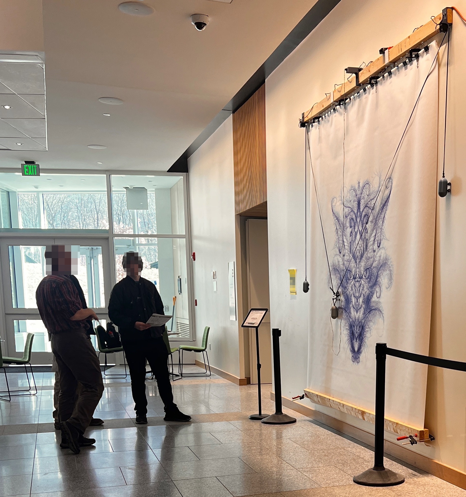
This is Gondola PlottyBot v2, a vertical pen plotter you can build.
It’s based on a Raspberry Pi Zero 2 W and comes loaded with software to make it easy to use. It’ll create its own wifi network to connect to, but you can also have it connect to an existing one. Then controlling it is web based.
Deployment size is arbitrary, you can make a small one or a really big one.


Downloads
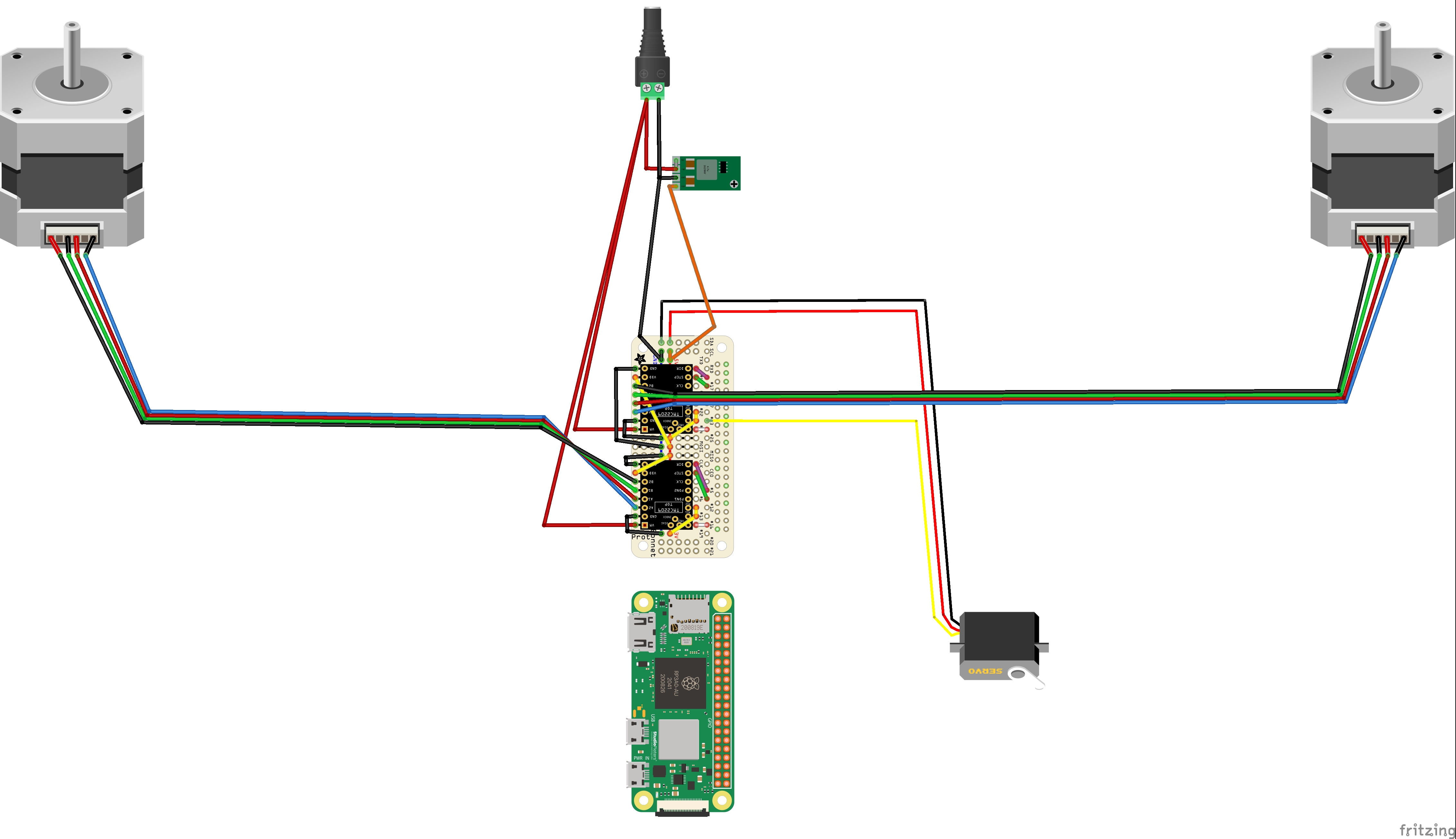
Circuit Diagram (optional: for reference)
Parts to Gather
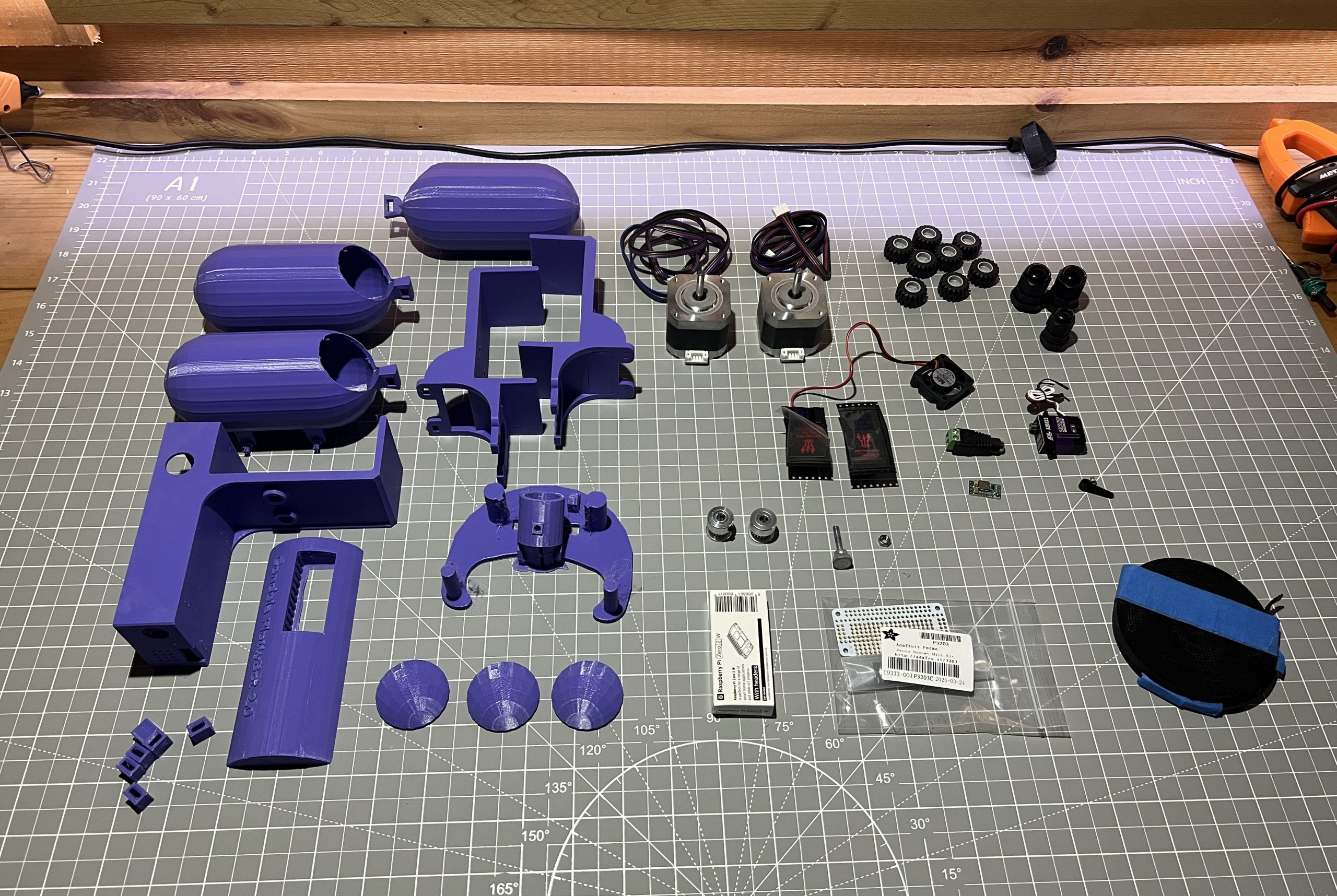
3D Printed
All parts available here: download link.
weight_cap_x3.stl
side_weight_x2.stl
gondola_weigth_x1.stl
belt_looper_x4.stl
gondola_x1.stl
logic_box_cover_x1.stl
logic_box_x1.stl
motor_holder_x2.stl
Each file name contains the amount to print at the end (x4 means print 4 of this part).
Acquired
Tools to have
- soldering iron
- glue gun (or sugru moldable glue)
- allen wrench set
- small phillips screwdriver
- needle nose pliers
- voltmeter (preferable)
- cordless drill (preferable)
- xacto knife
- wire snippers
Circuit
Here is the circuit diagram for reference. It is not needed for the instruction point out what to connect where, it’s only useful to cross-reference information.
Build Instructions
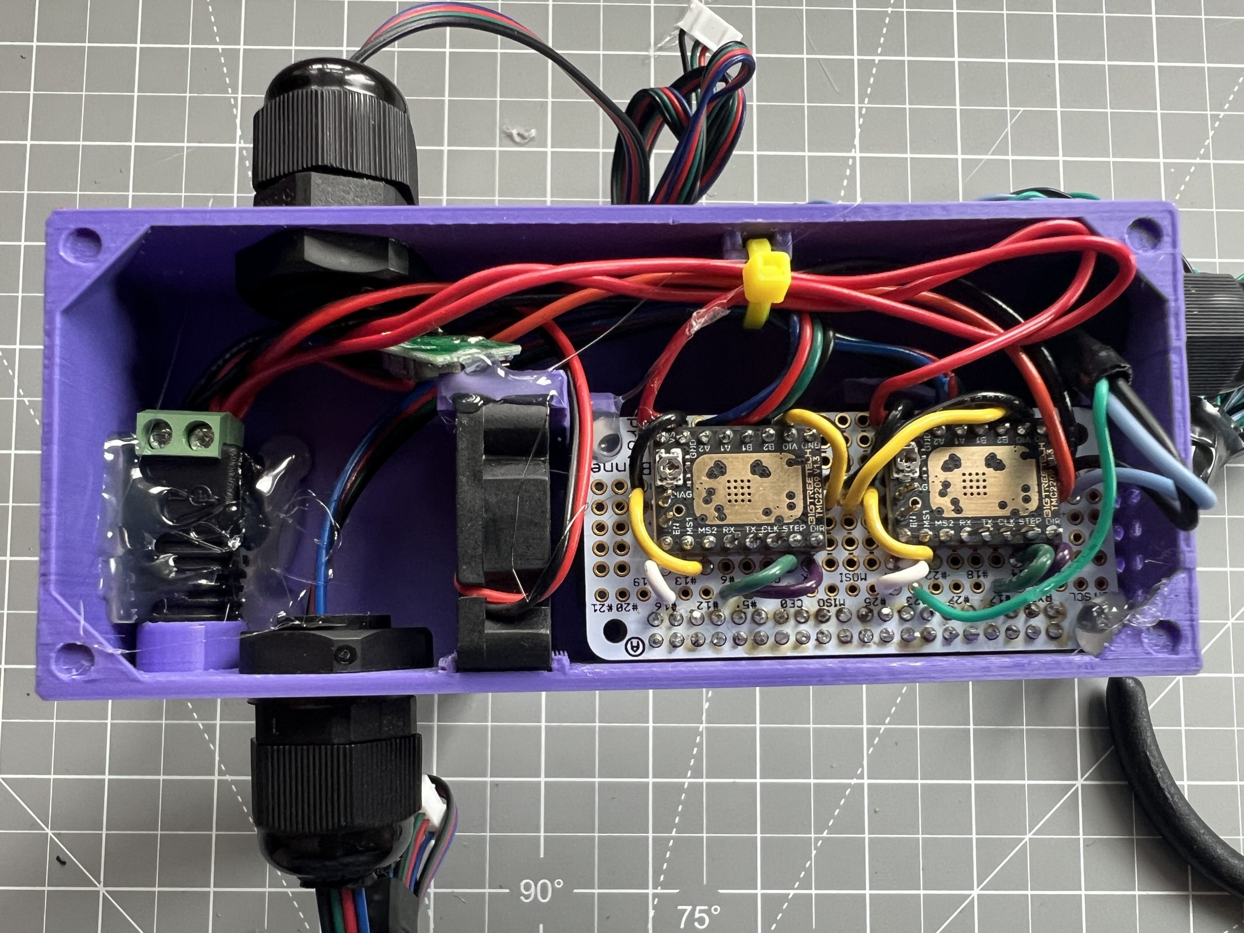
Logic Box
This is the meat of the project.
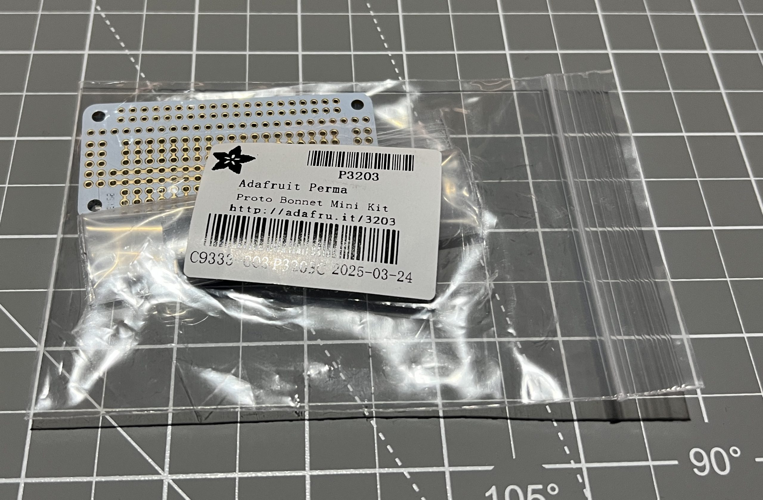
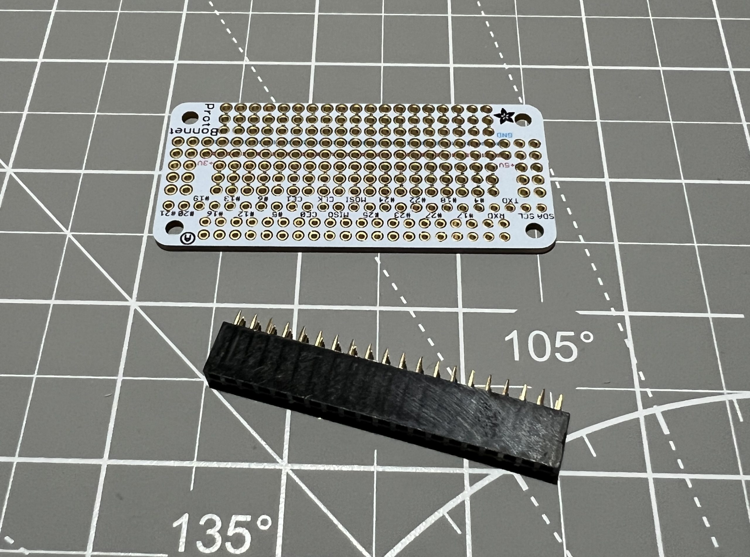
Perma Proto Bonnet Headers
Parts
Perma Proto Bonnet Mini Kit x1
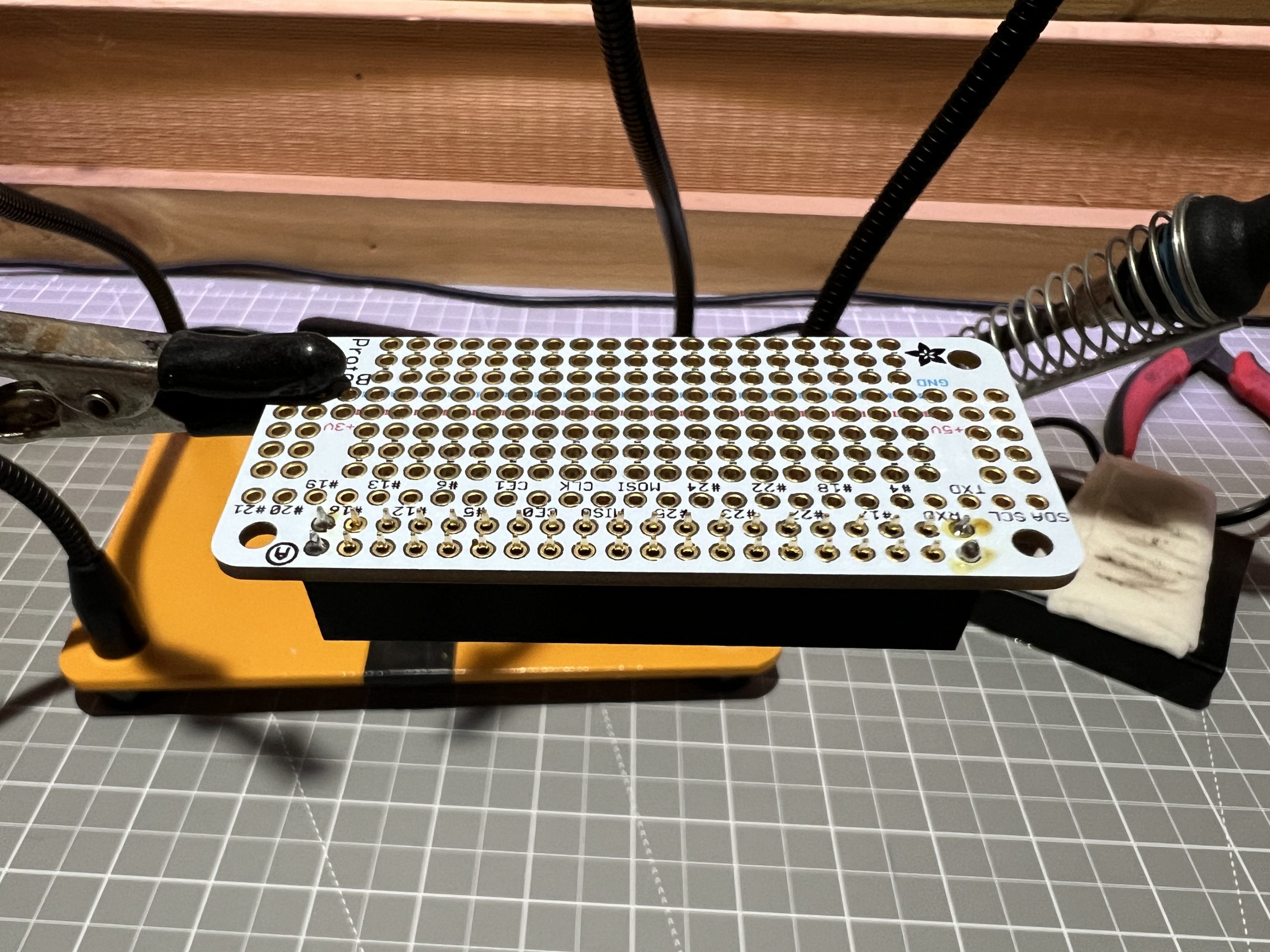
First we’ll solder the headers the Perma Proto Bonnet came with. In years of building drawing machines, the Bonnet approach seems to be the best mix for building a stable machine while keeping some flexibility in building.
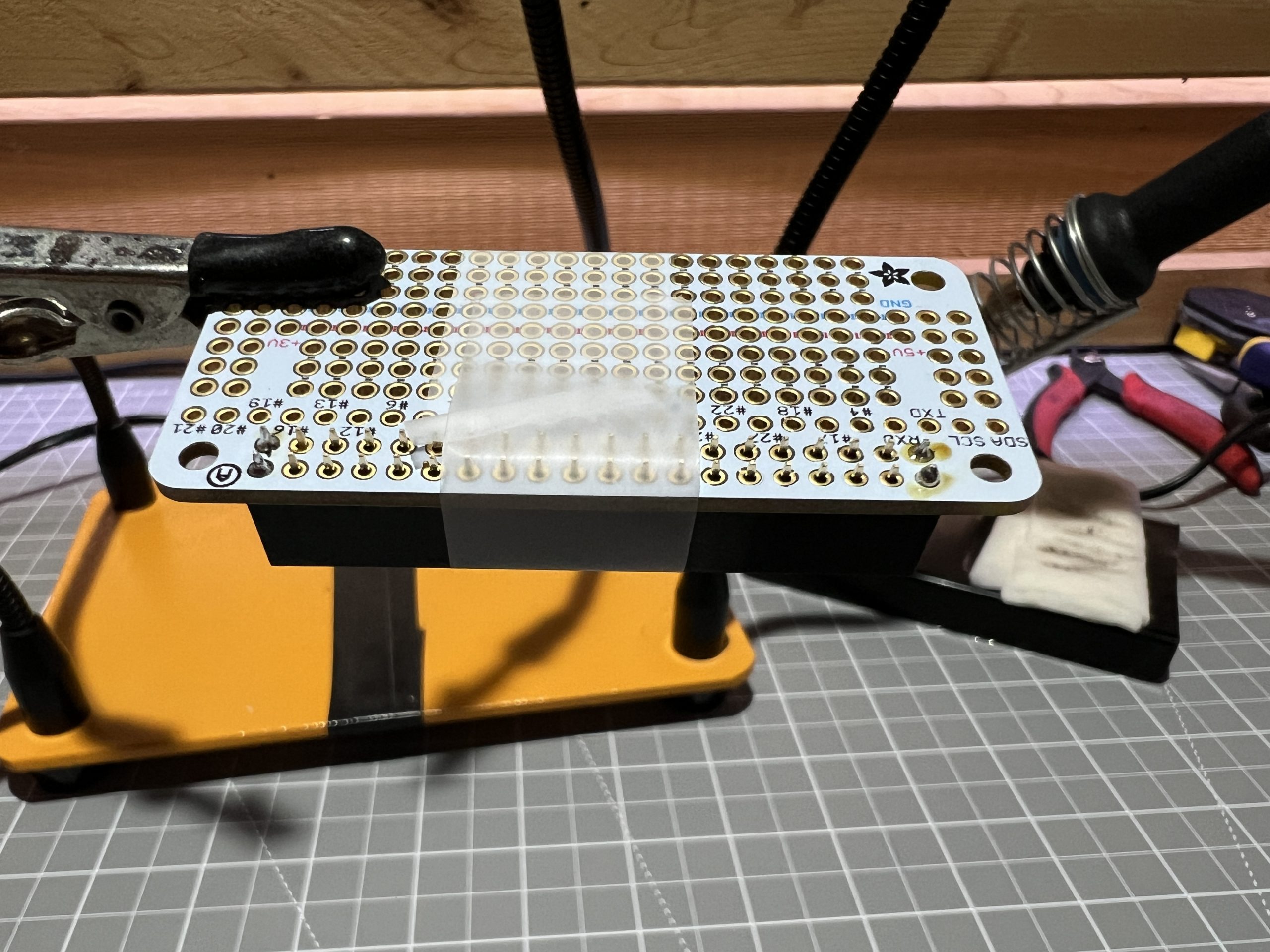
You an use tape to hold the header in place and solder a couple of pins to hold it instead of the tape.
Power to the Pi
Parts
12V power supply x1
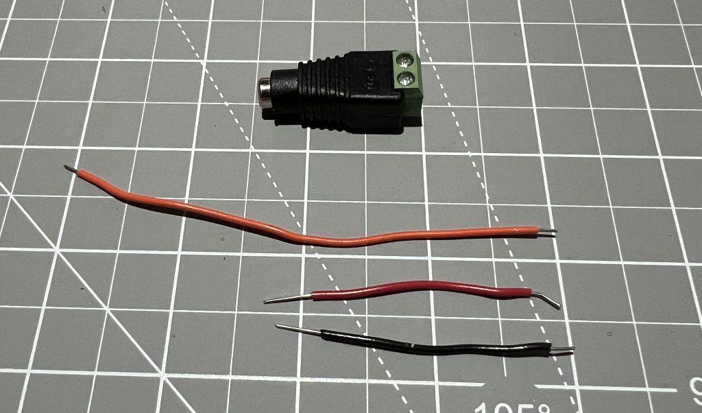
12V power connector (female) x1
5V voltage regulator x1
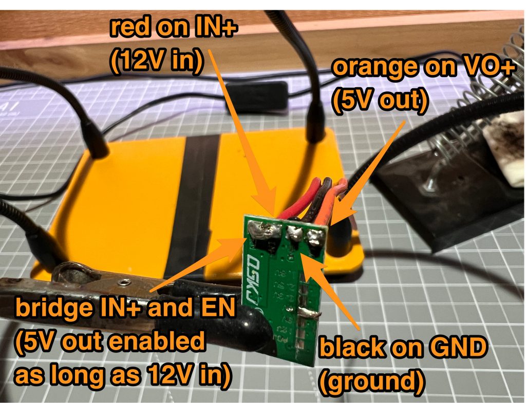
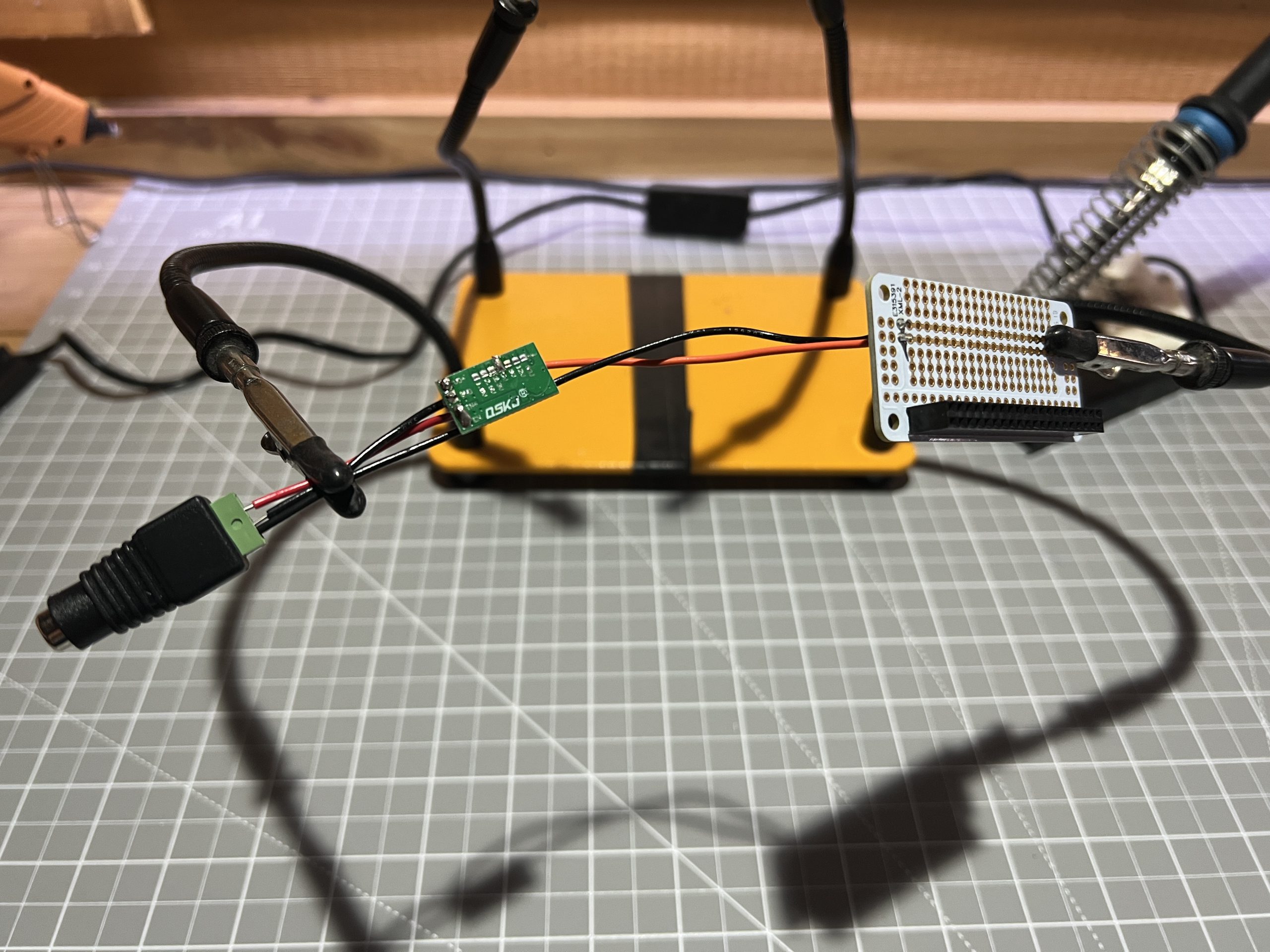
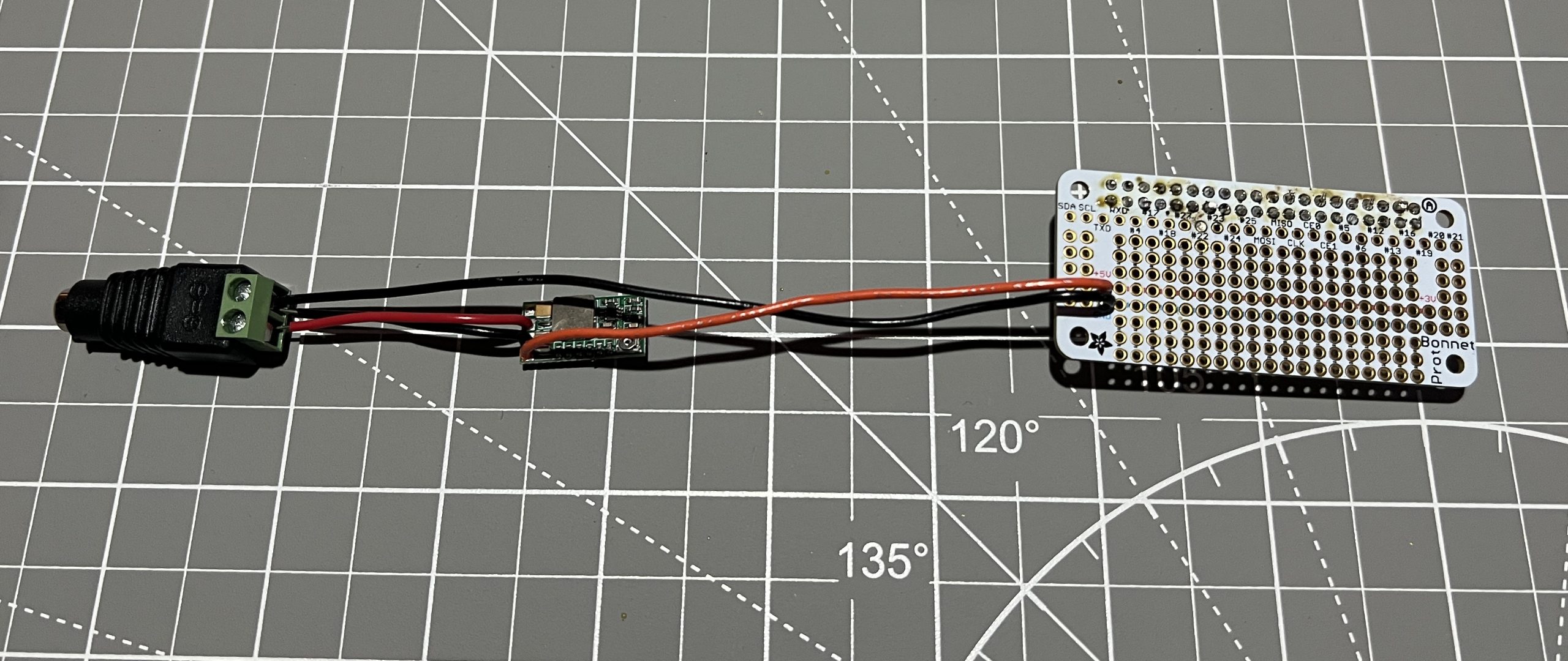
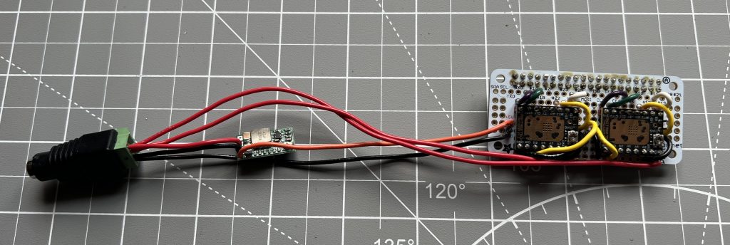
Grab the 5V voltage regulator

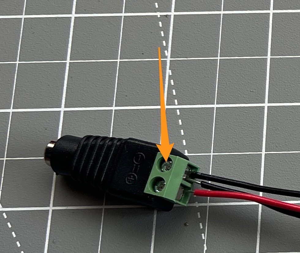
We will hard set it to give us 5V, to do so we cut the potentiometer out, and we solder the 5V option.

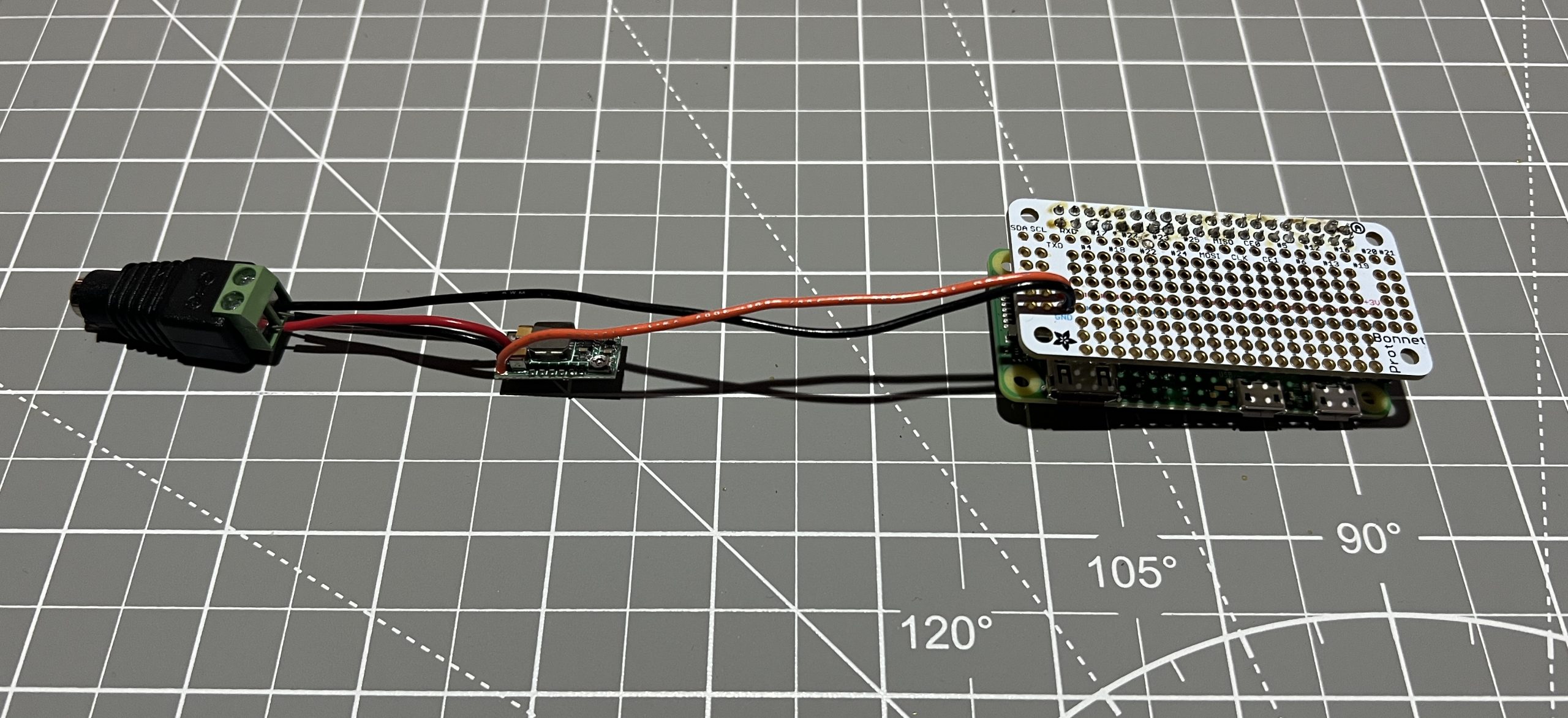
Then we solder the female 12V power connector.
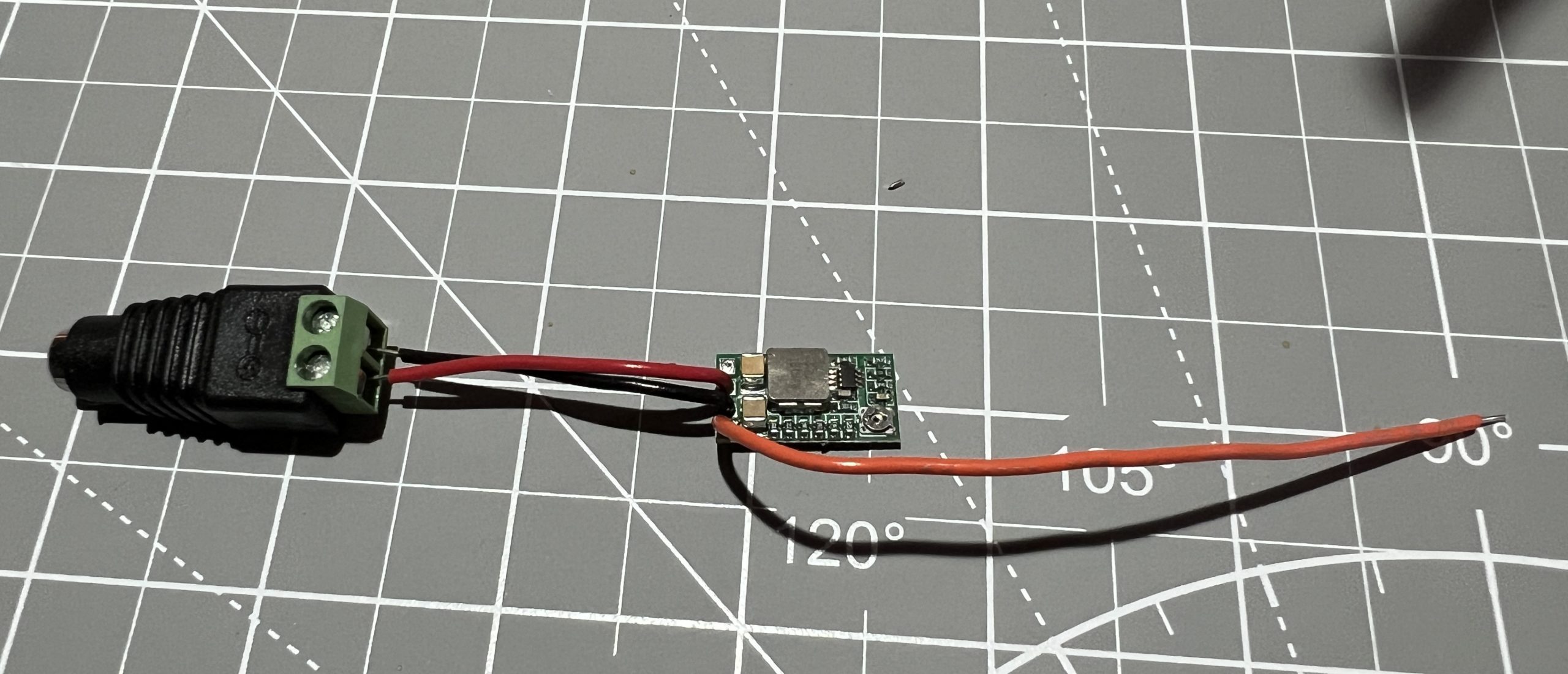
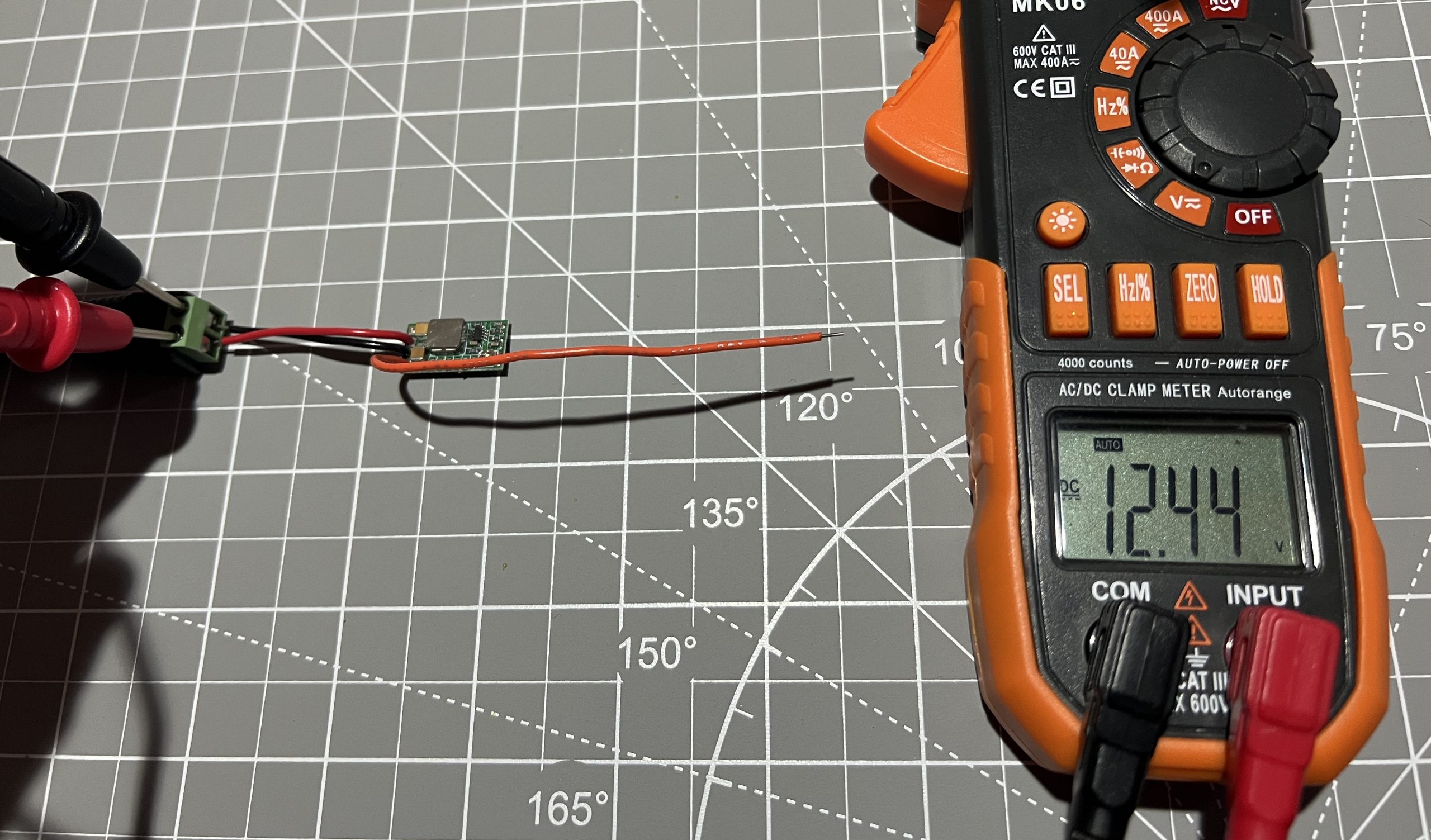
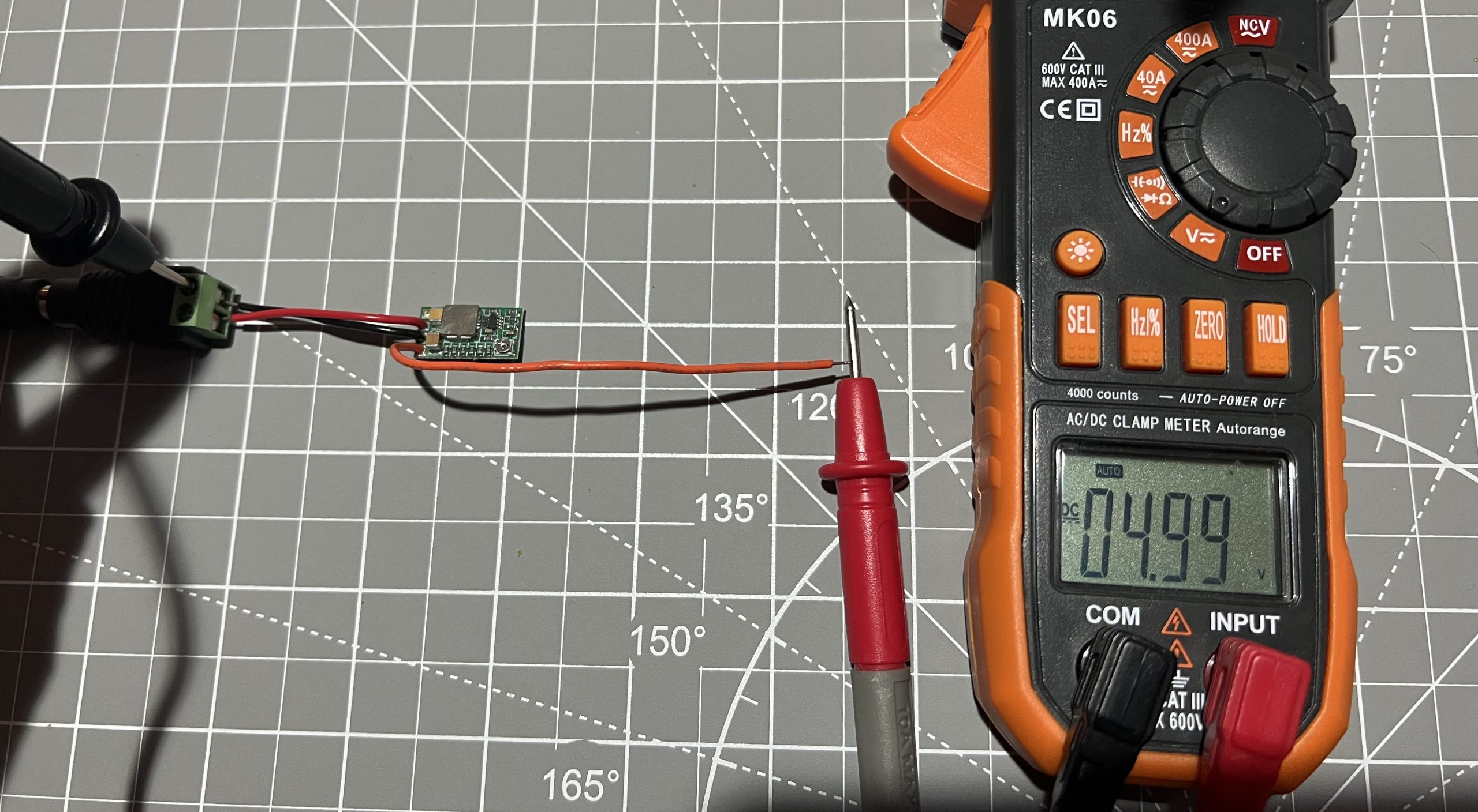
Plug it into the 12V power supply, make sure you have 12V at the supply side, and 5V at the orange wire.
Perfect, now let’s solder it into the Perma Proto Bonnet !! make sure the power supply is unplugged first !!
First Pi Boot
Parts
Raspberry Pi 2 Zero W x1
SD Card x1
With the power supply still unplugged, attach the bonnet to the Pi.
Download the Gondola PlottyBot Pi image, and write it to the SD card using the Rapsberry Pi Imager. When you get to the “OS” section, scroll all the way to the bottom to “Use custom” and point to the img file you just downloaded.

Stick the SD card in the Pi, plug in the power supply and you should see the Pi’s LED light up.

Now this first boot will take a good 10 to 15 minutes. It’s a good idea to not get impatient a unplug it. The first time things start, a whole lot of packages are being installed on a Pi Zero which is not exactly the spiffiest machine out there :). Rest assured it’ll have more than enough horsepower to run the plotter once everything is installed. You will know it’s done installing when a new wifi network shows up.

Go ahead and connect to it. Once connected, point your browser to http://plottybot.local (or http://10.0.0.5 if this didn’t work). You should see Gondola PlottyBot’s web interface:
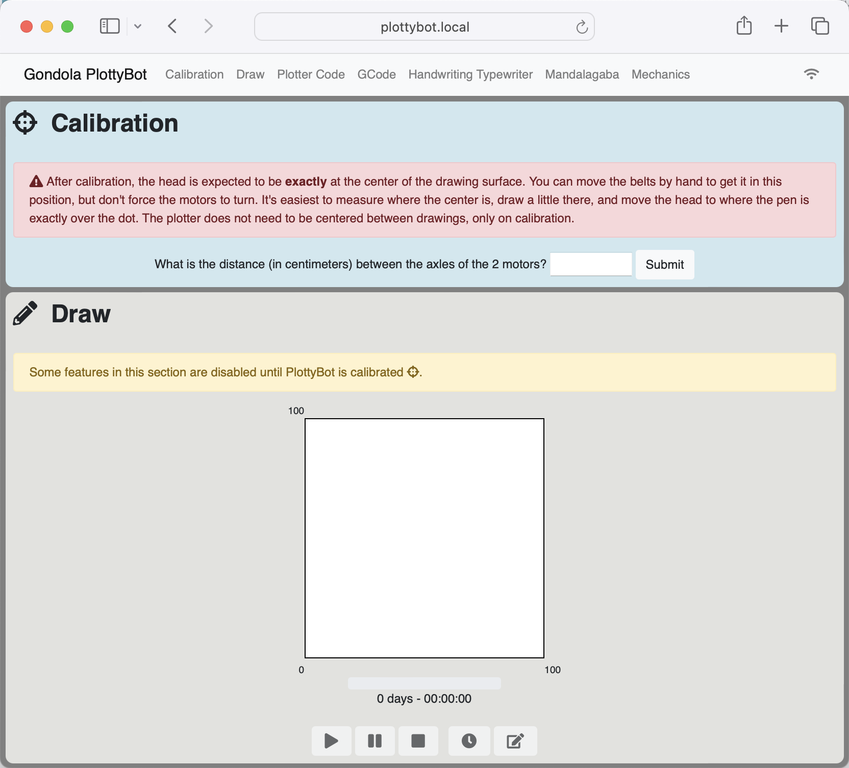
Super! No need to do anything in there we just wanted to make sure it worked. Let’s unplug the power supply, we’ll keep working on our circuit.
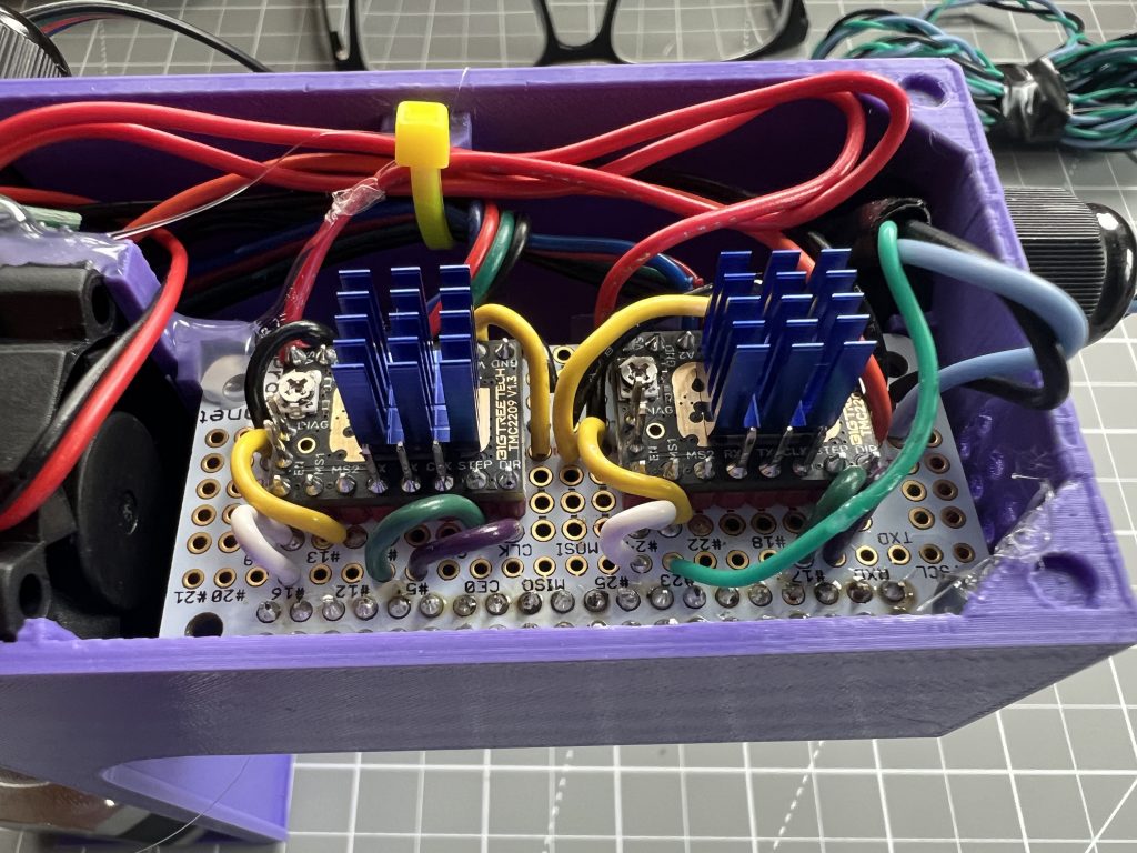
Stepper Motor Drivers
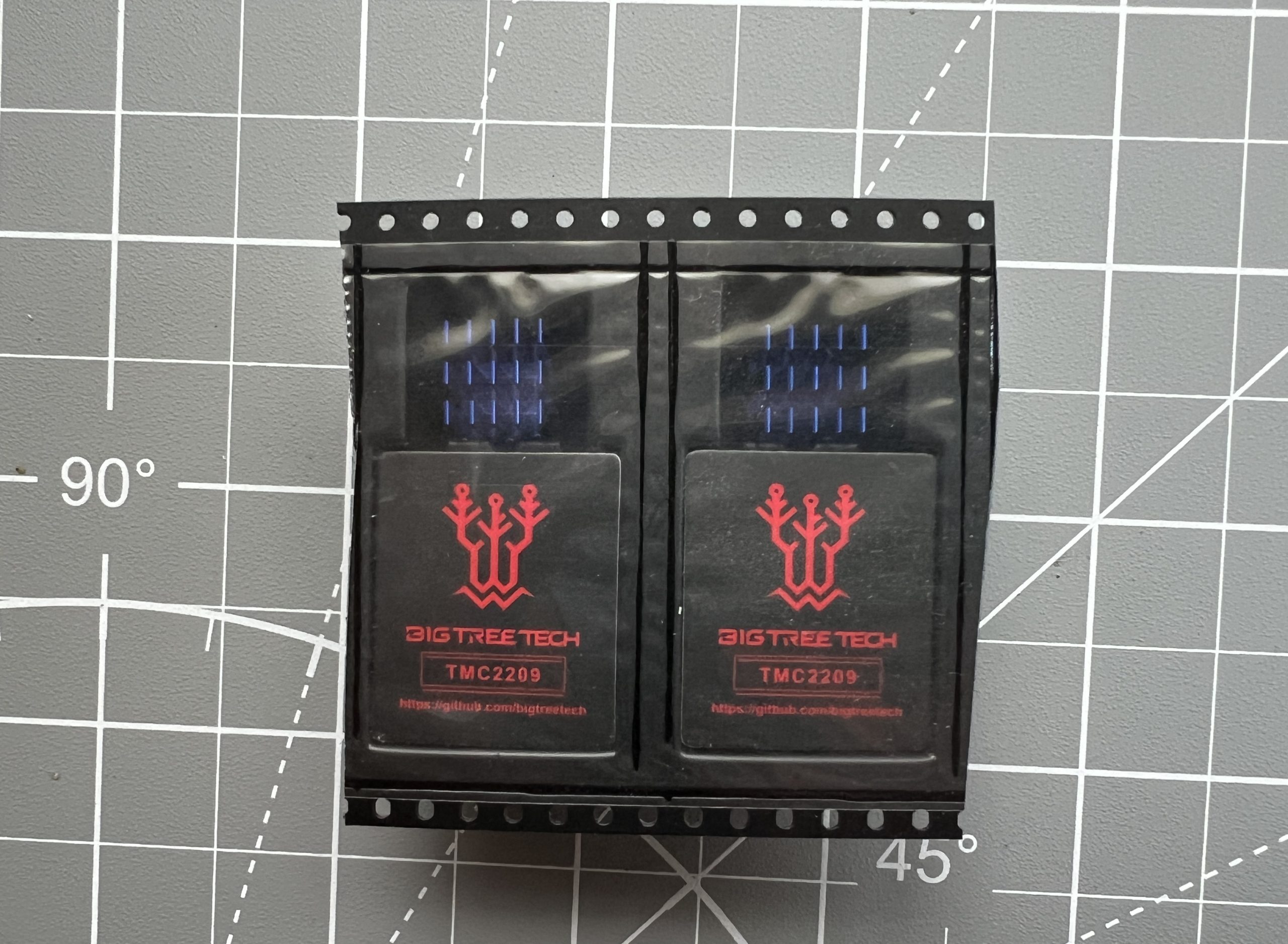
Parts
stepper driver x2
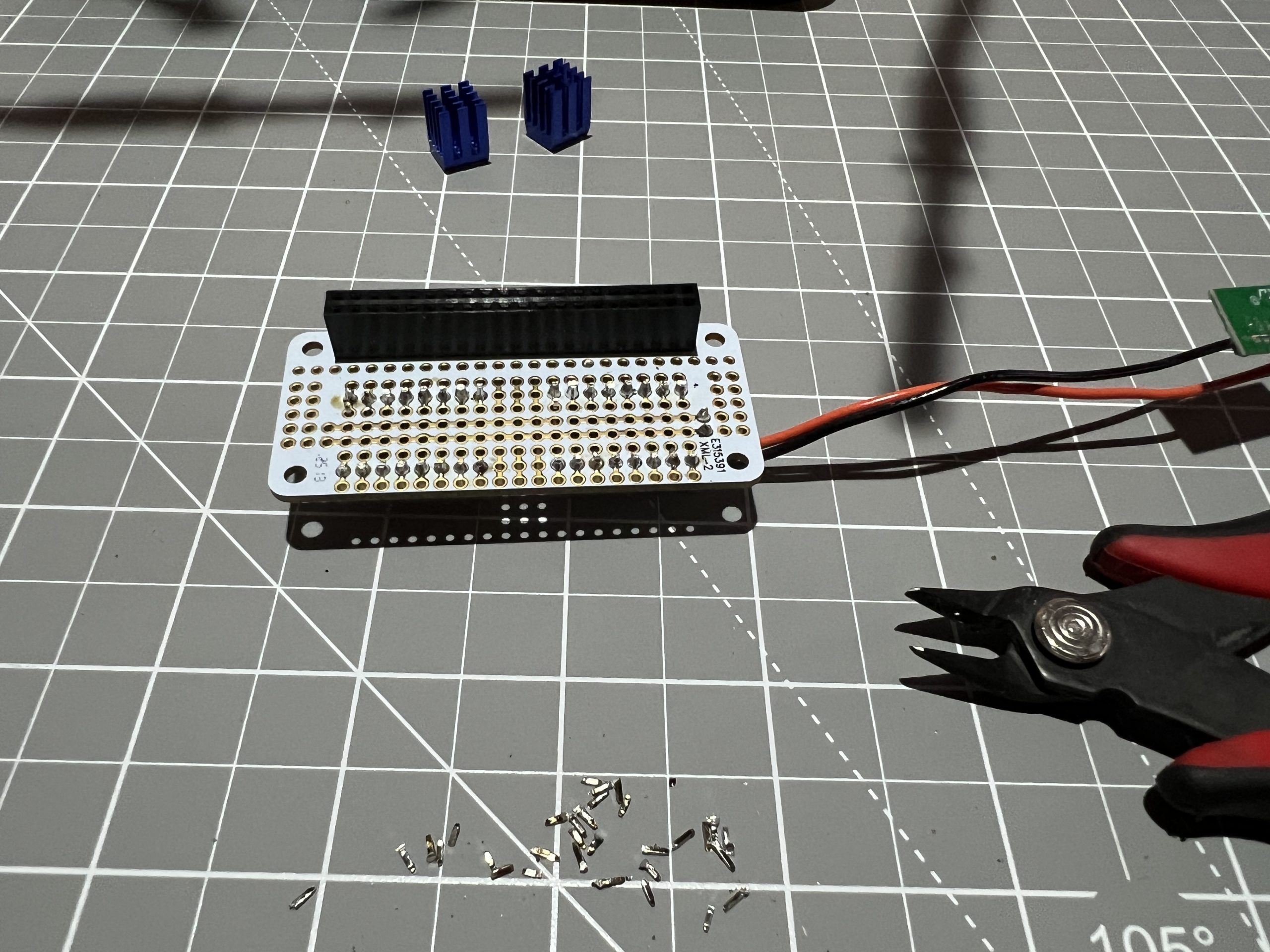
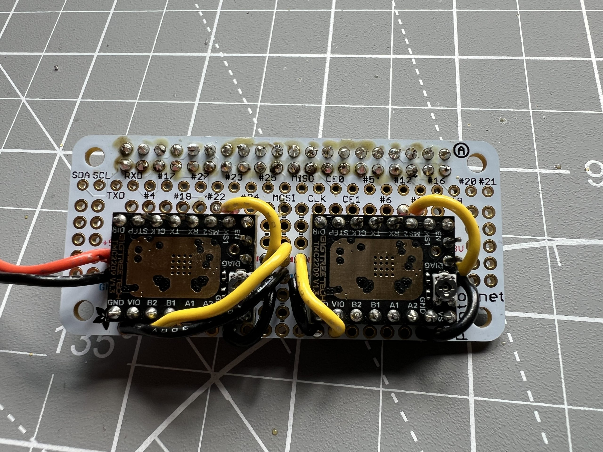
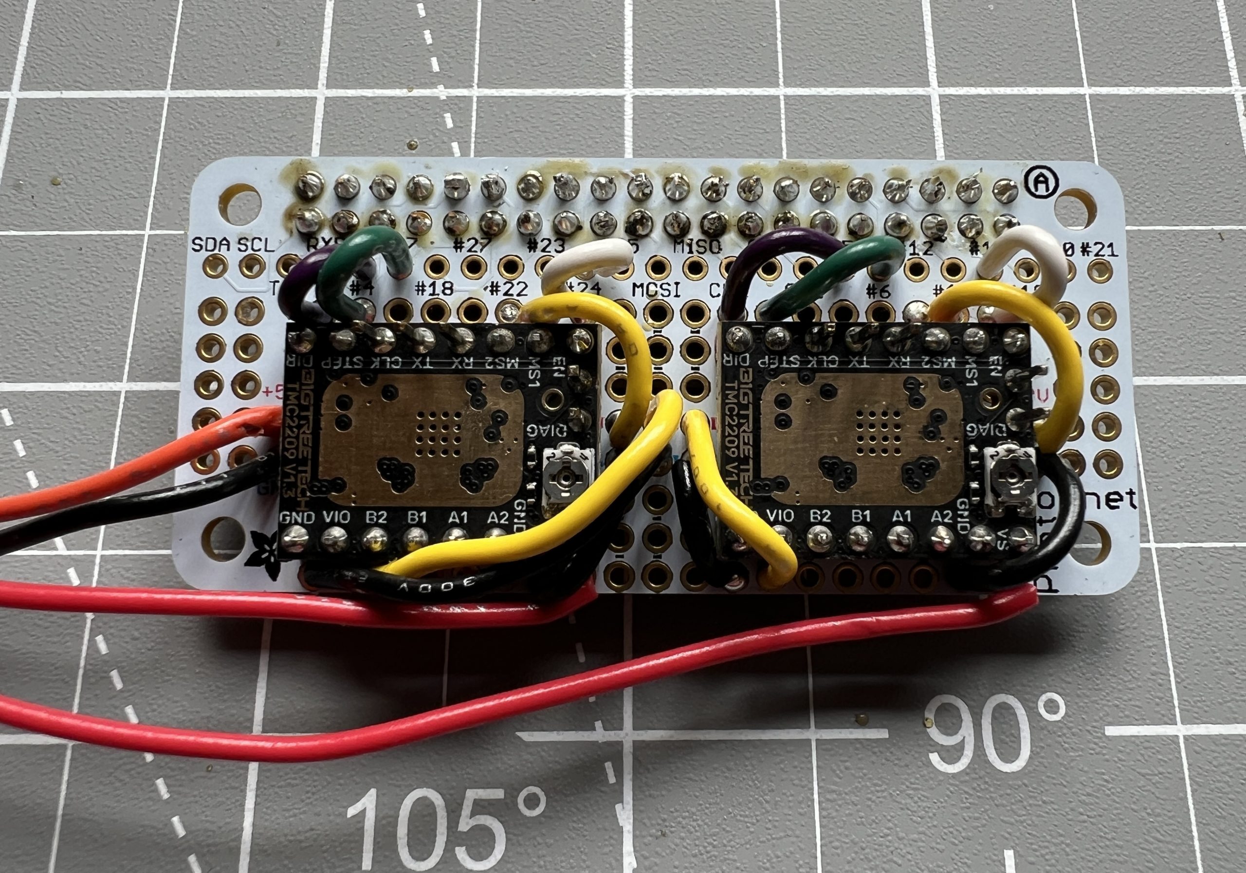
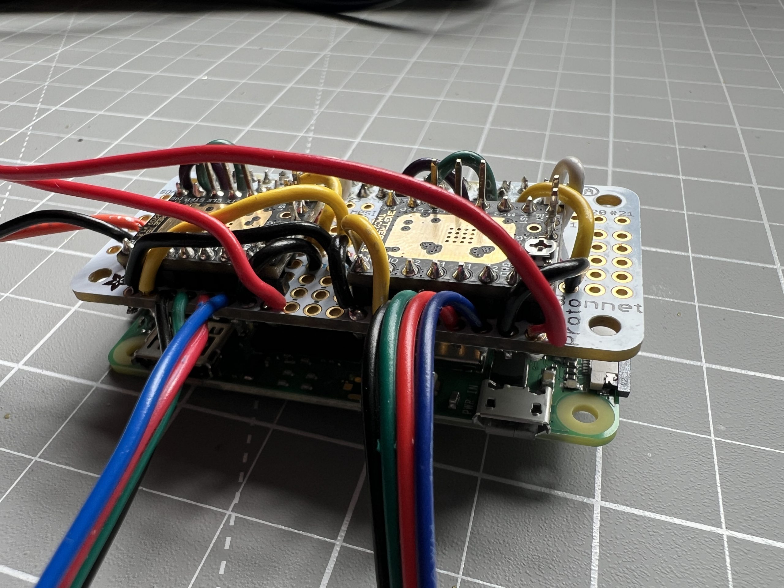
The stepper drivers have 2 pins which aren’t useful and will get in the way of circuitry so we snip them out.
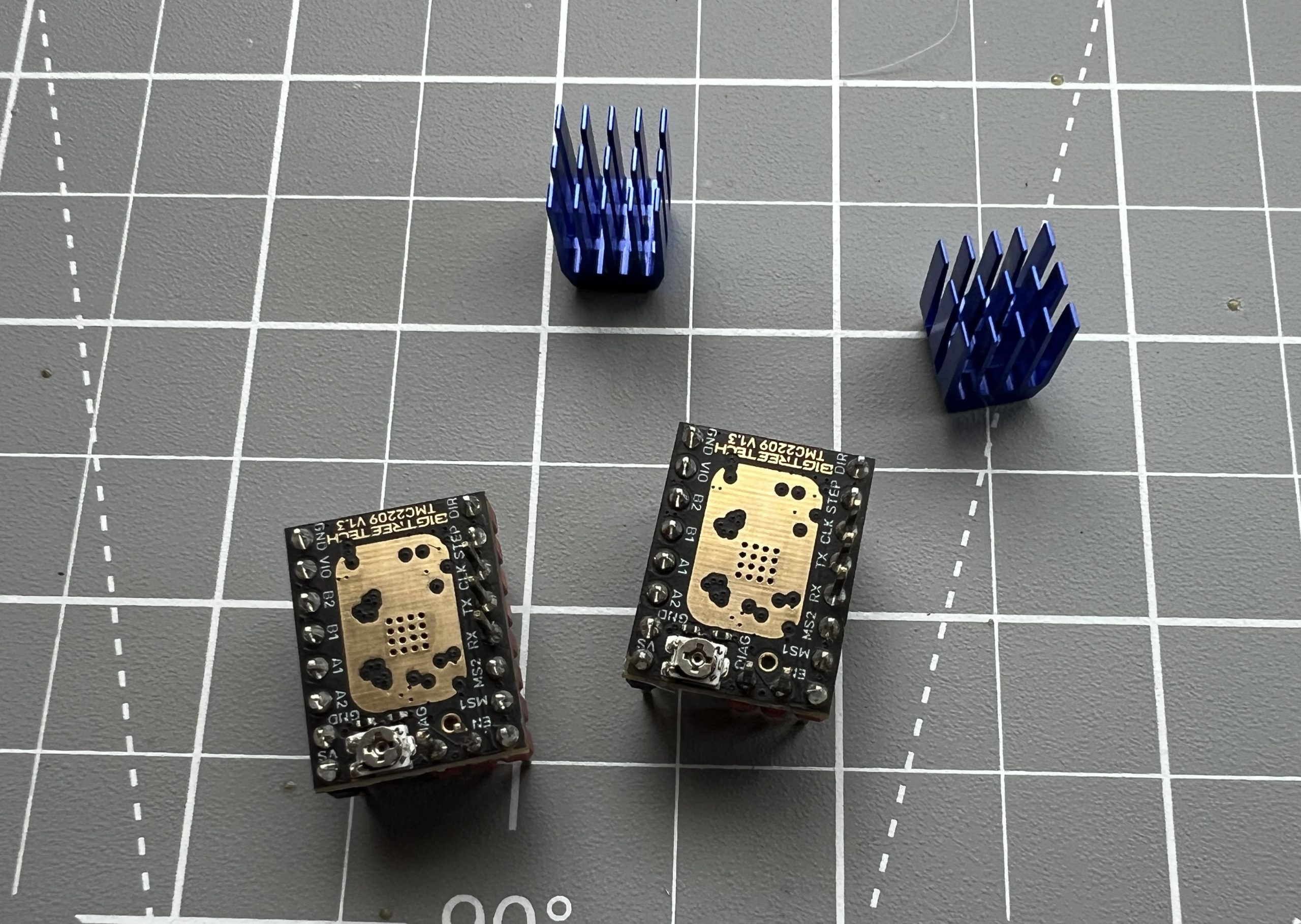
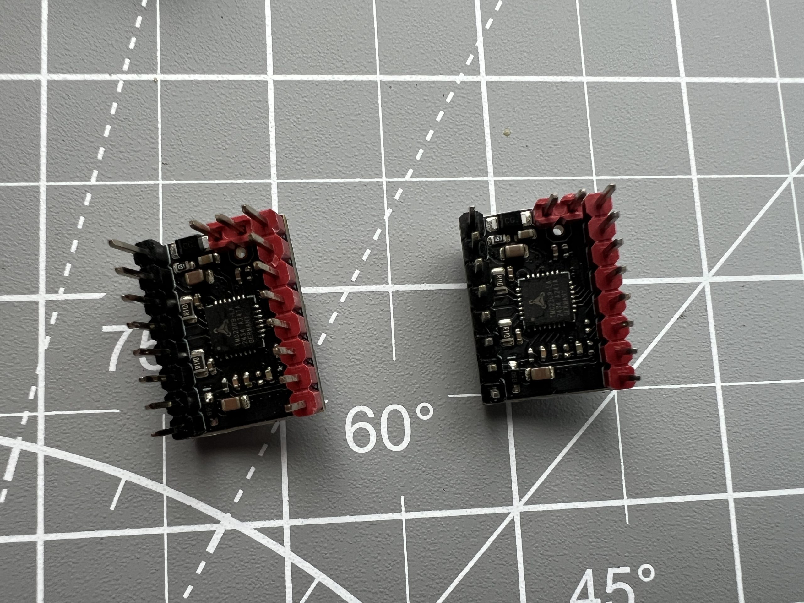
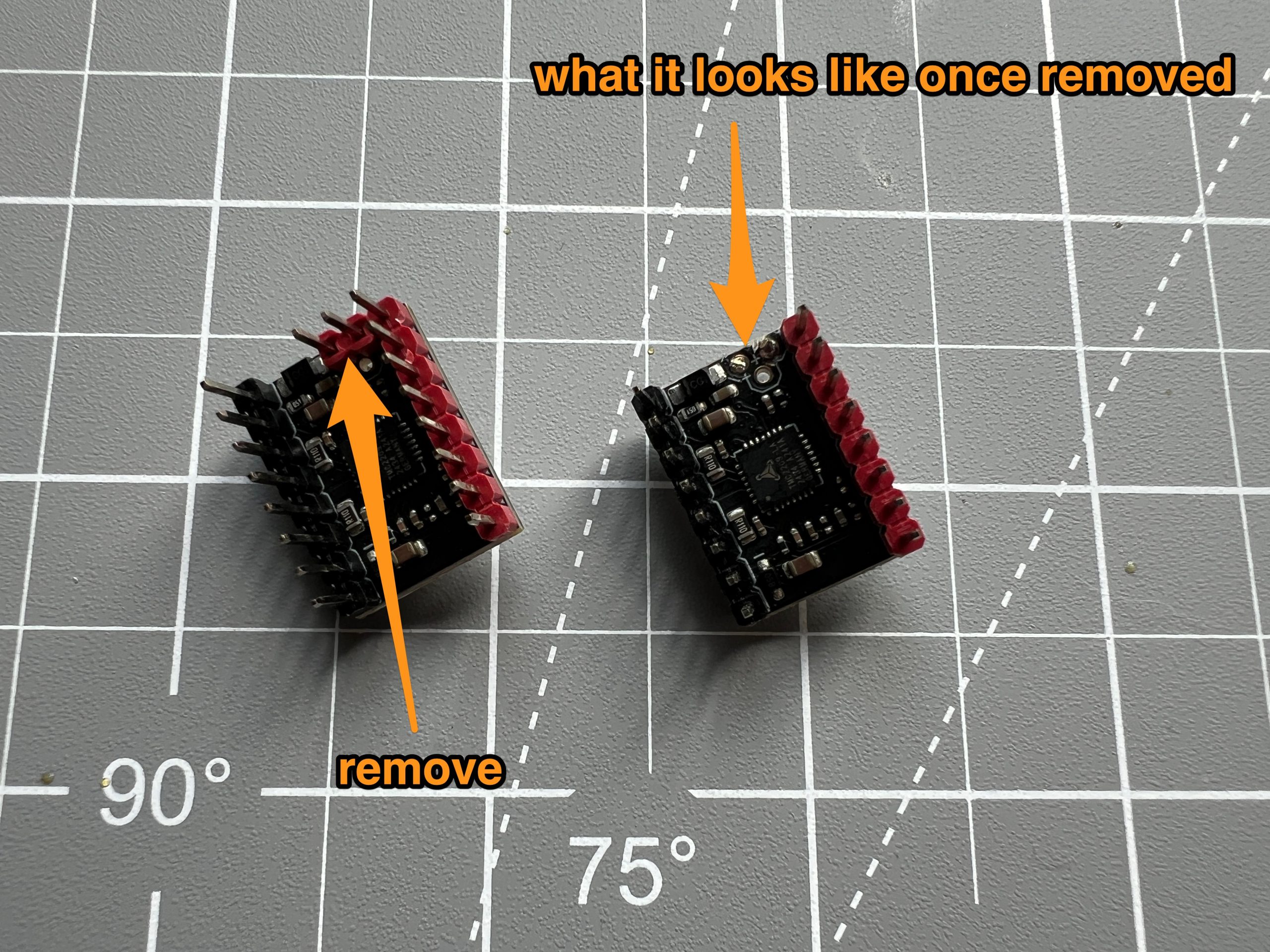
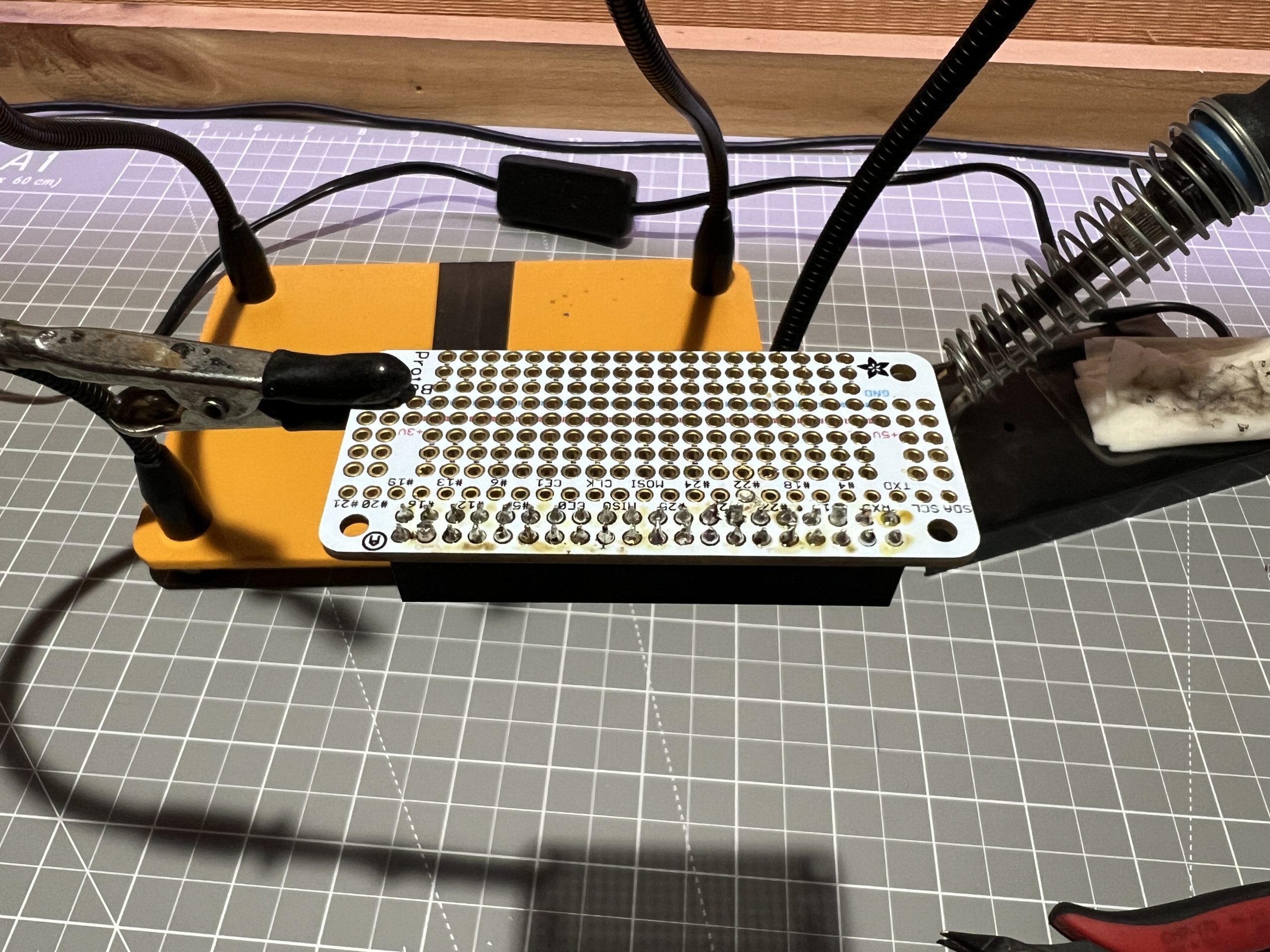
Do so for the both of them. Then position them on the proto bonnet, and solder their pins on the bottom side.

Whenever we solder something on the bottom side, we snip out extraneous tails.
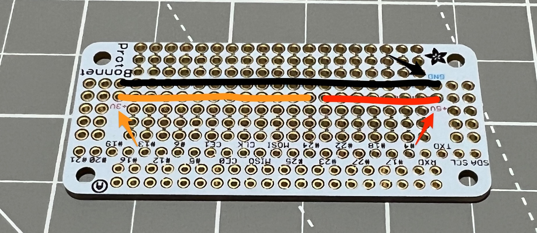
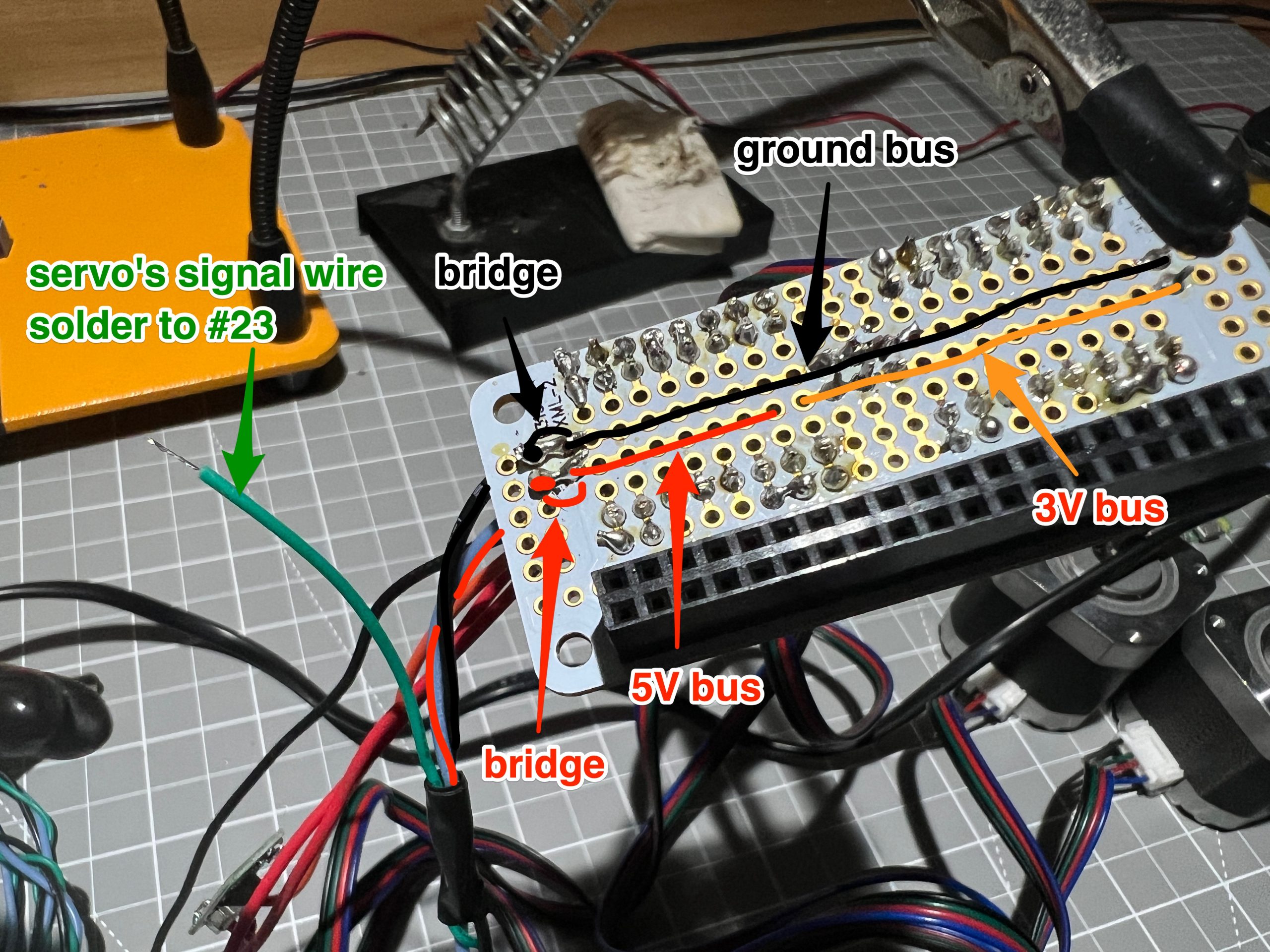
Watch your proto bonnet, it has a 5V bus and a 3V bus. They are separated even though they follow the same line, you want to make sure you tap into the right bus when you bring voltage somewhere. The ground bus is running continuously parallel to them.
We bring 3V to them to their MS1 pin.
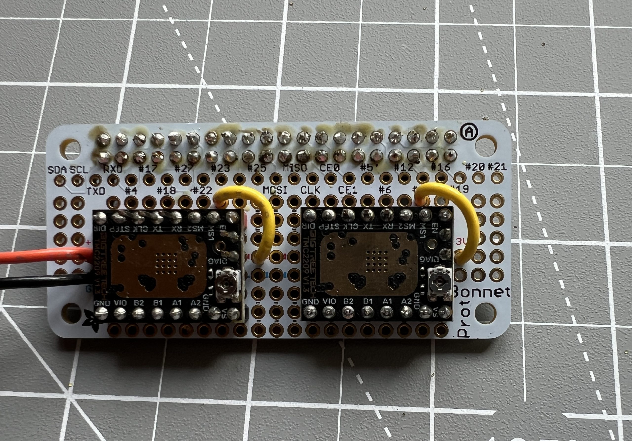
When we solder it, on the other side we bridge the MS1 pin with the MS2 pin so they will both get 3V.
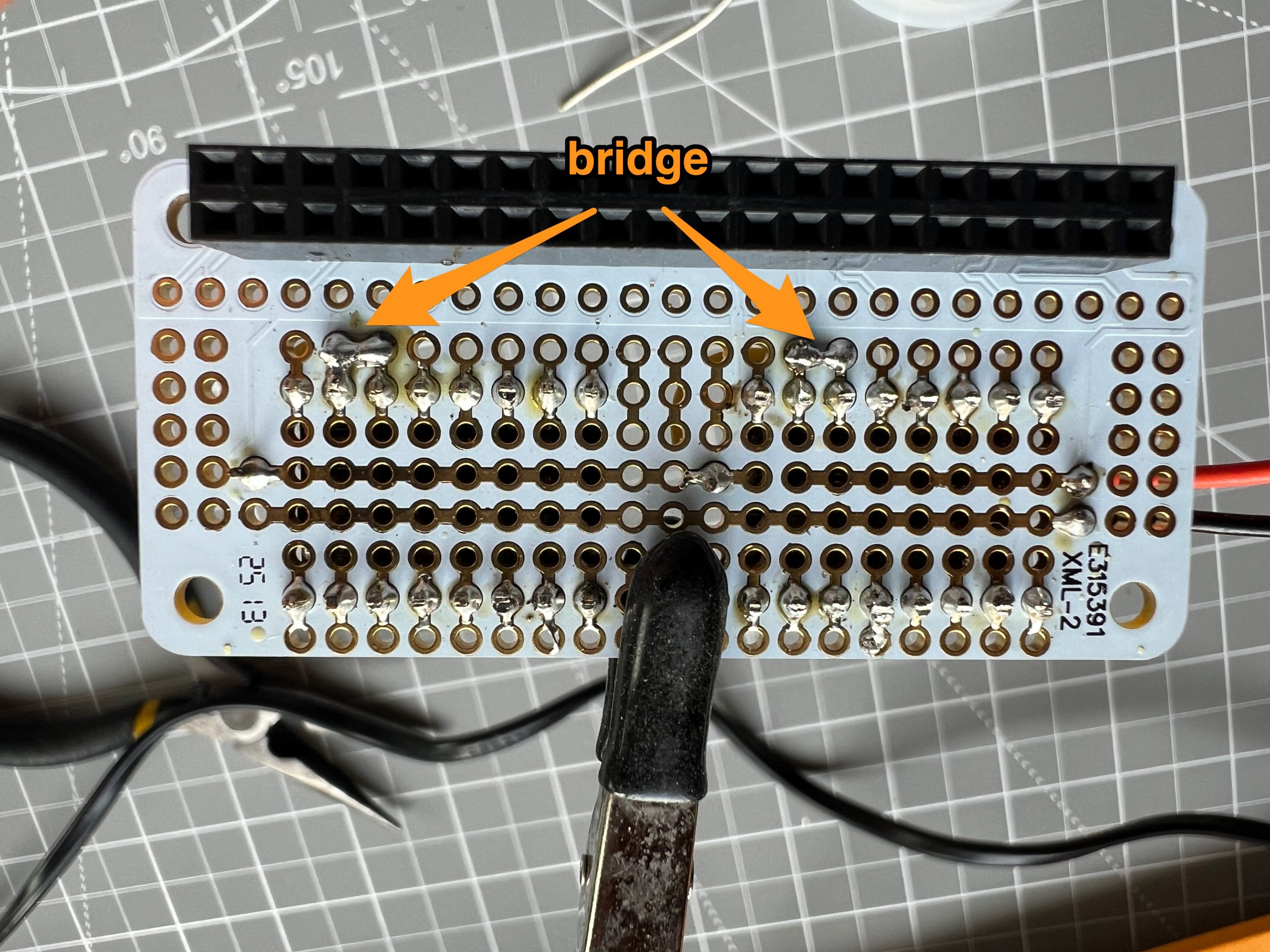
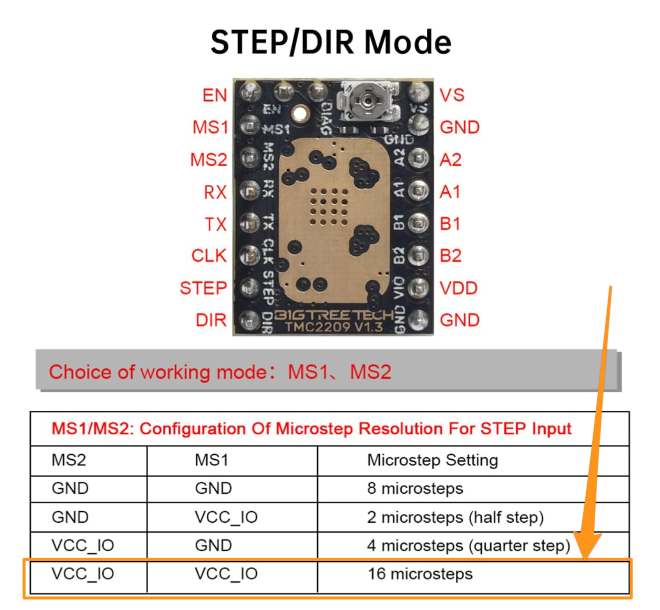
The documentation for these stepper drivers says that pulling both MS1 and MS2 up activates the highest microstepping.
We also bring 3V to their VIO pin. This is to power them.

They need 2 grounds each, so we bring 4 wires from the GND bus to their GND pins.
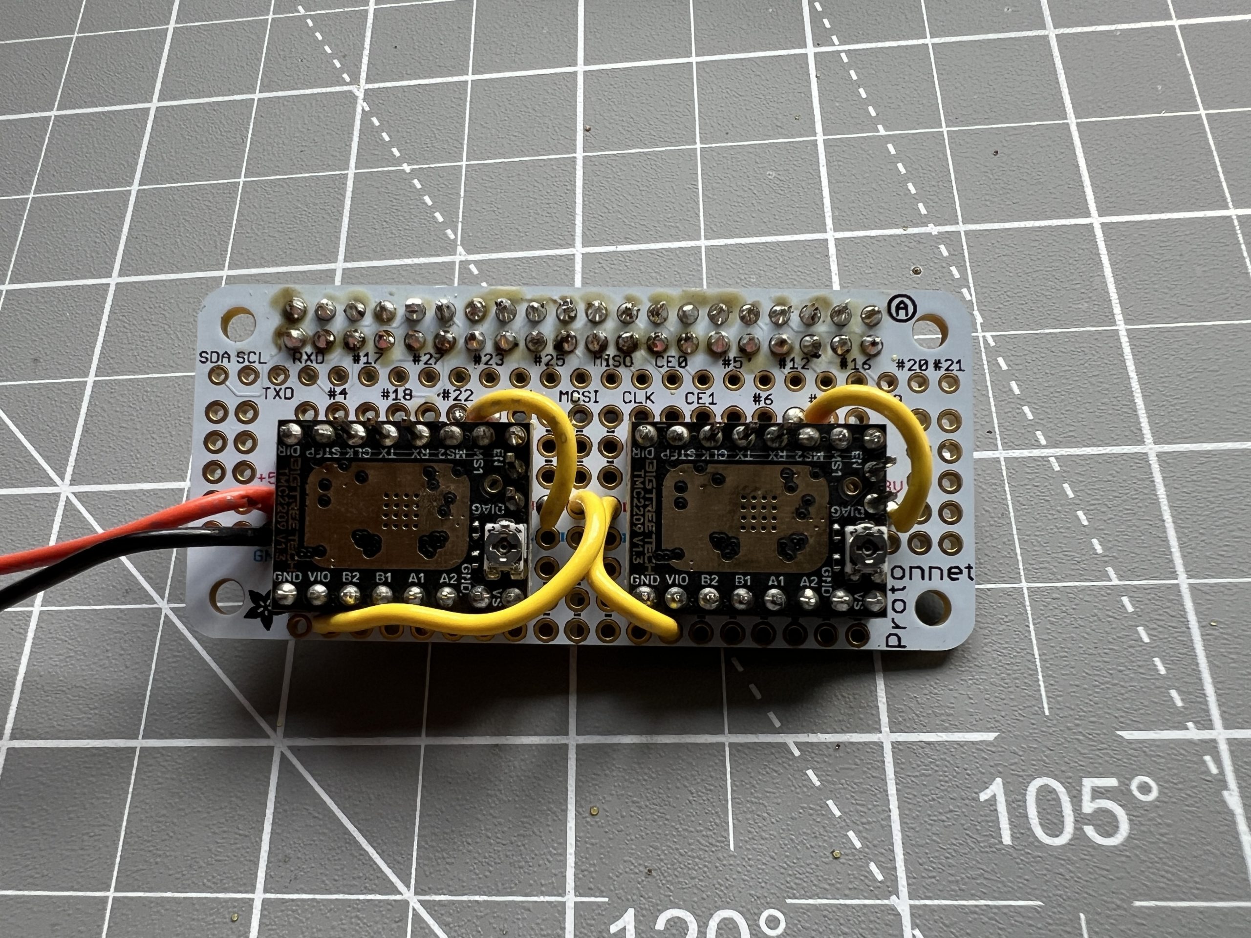
We bring Pi header pins #4 & #5 to the stepper drivers’ DIR (direction) pins.
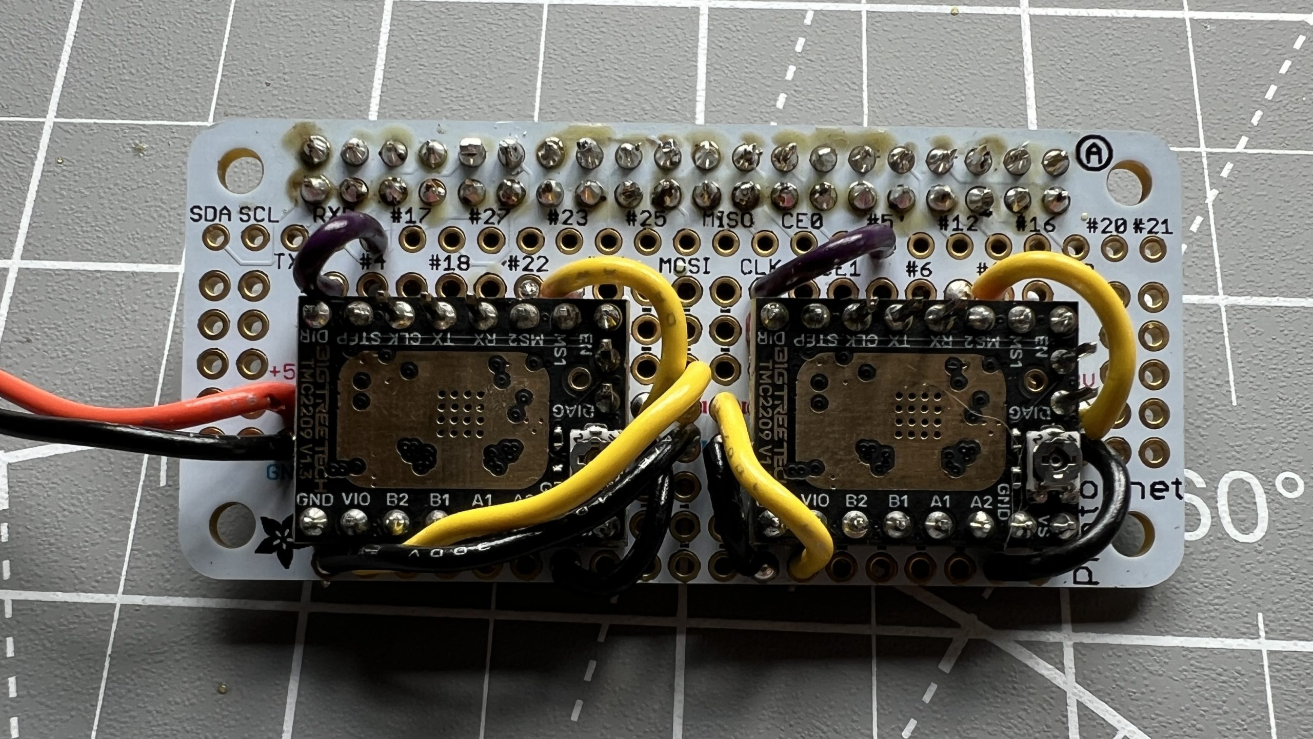
Then we bring Pi header pins #17 & #6 to the stepper drivers’ STEP pins.
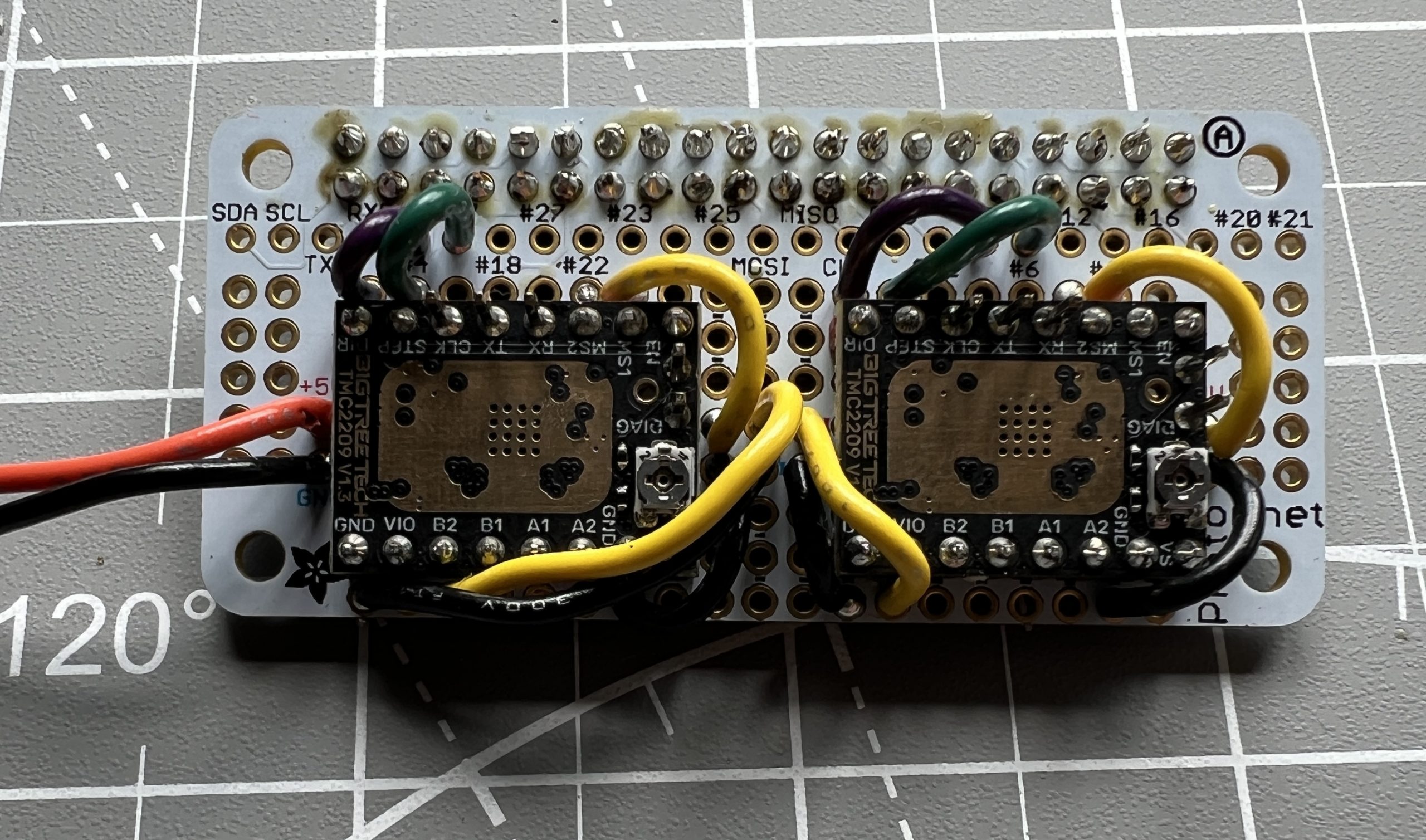
Then we bring Pi header pins #24 & #16 to the stepper drivers’ EN (enable) pins.
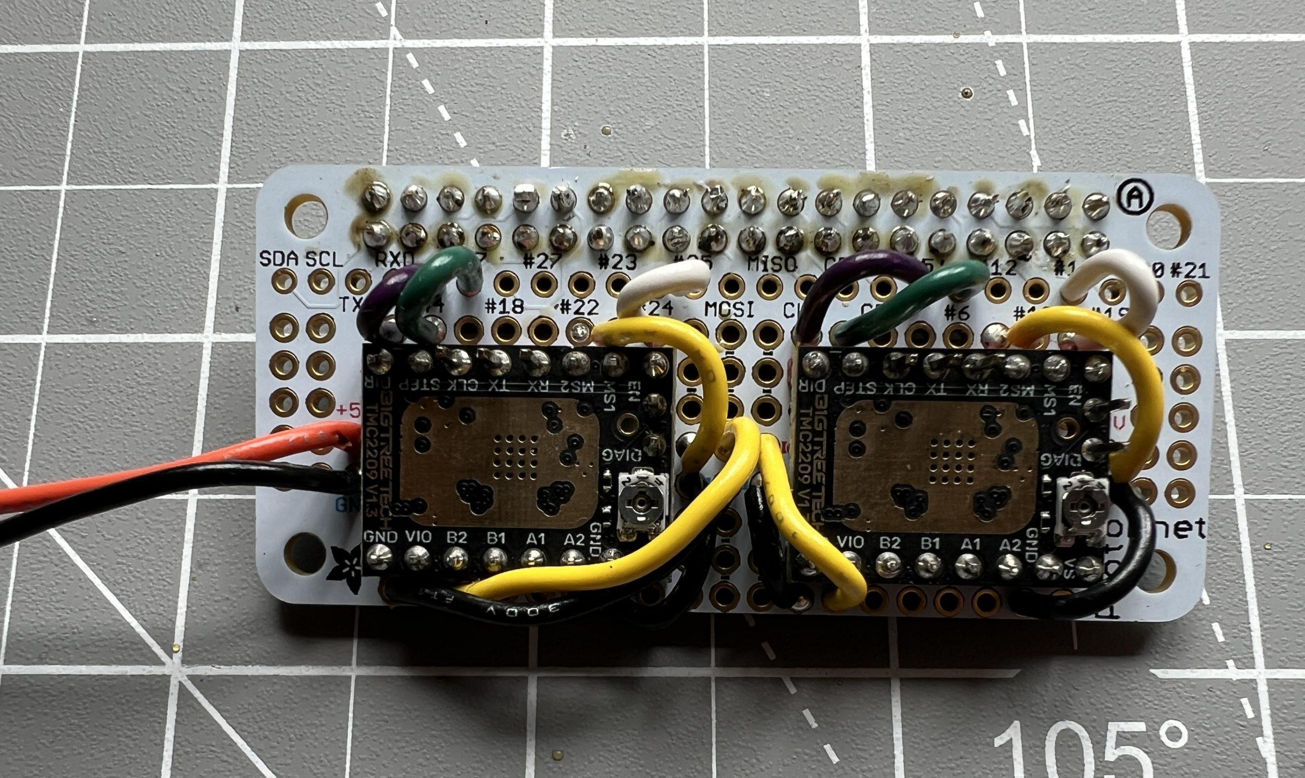
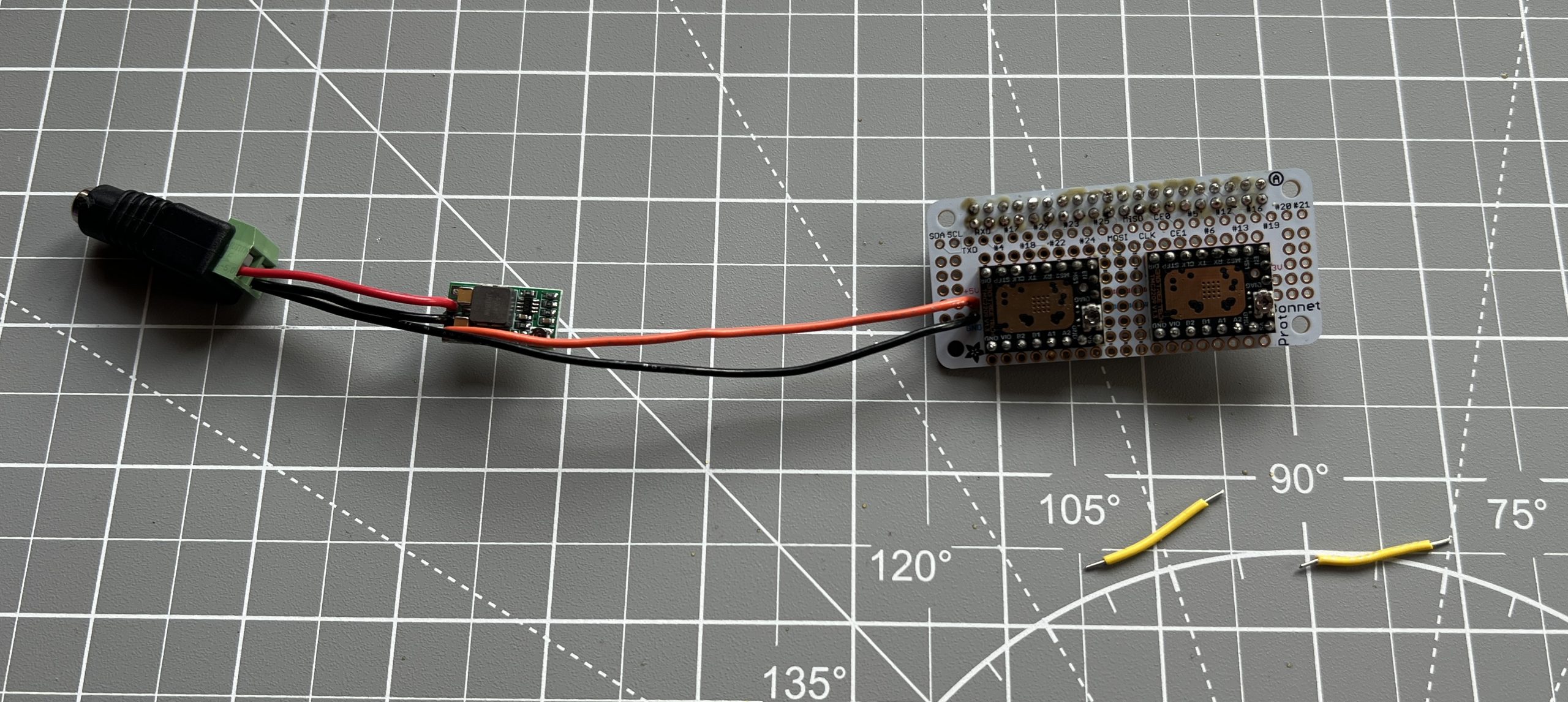
Finally we add 2 wires to our female 12v connector and solder that into each driver’s VS (Volt Supply?) pin. This power is for the motors. The stepper drivers need only 3v to run their logic which they get from the Pi, but the stepper motors need an independent 12v.
Space is getting tighter, and we’re about to make it worse. We are close to the end though, and it won’t get much more complicated than this.
Grab the 2 cables that came with your stepper motors. Make note of which end plugs into the stepper motor and which one is meant to go to a logic board. Snip & strip the end that goes into a logic board for the both of them (the pictures bellow only show 1).
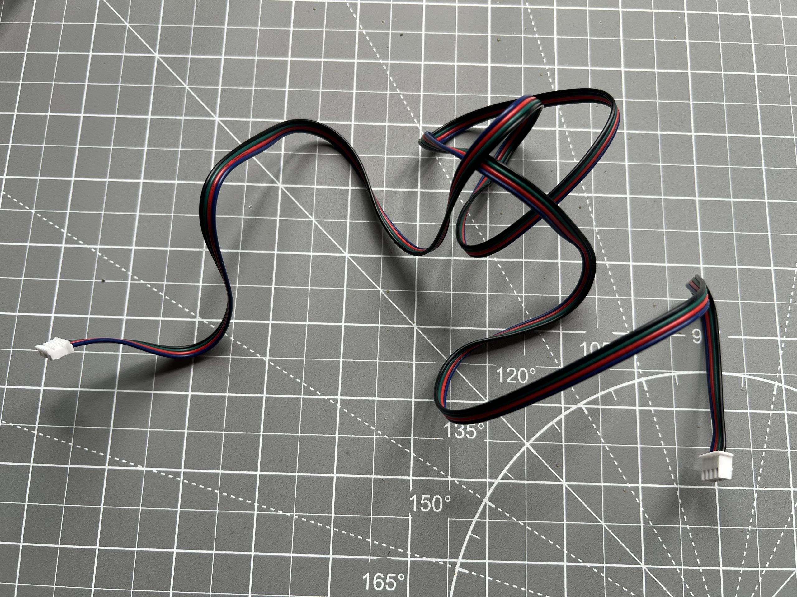
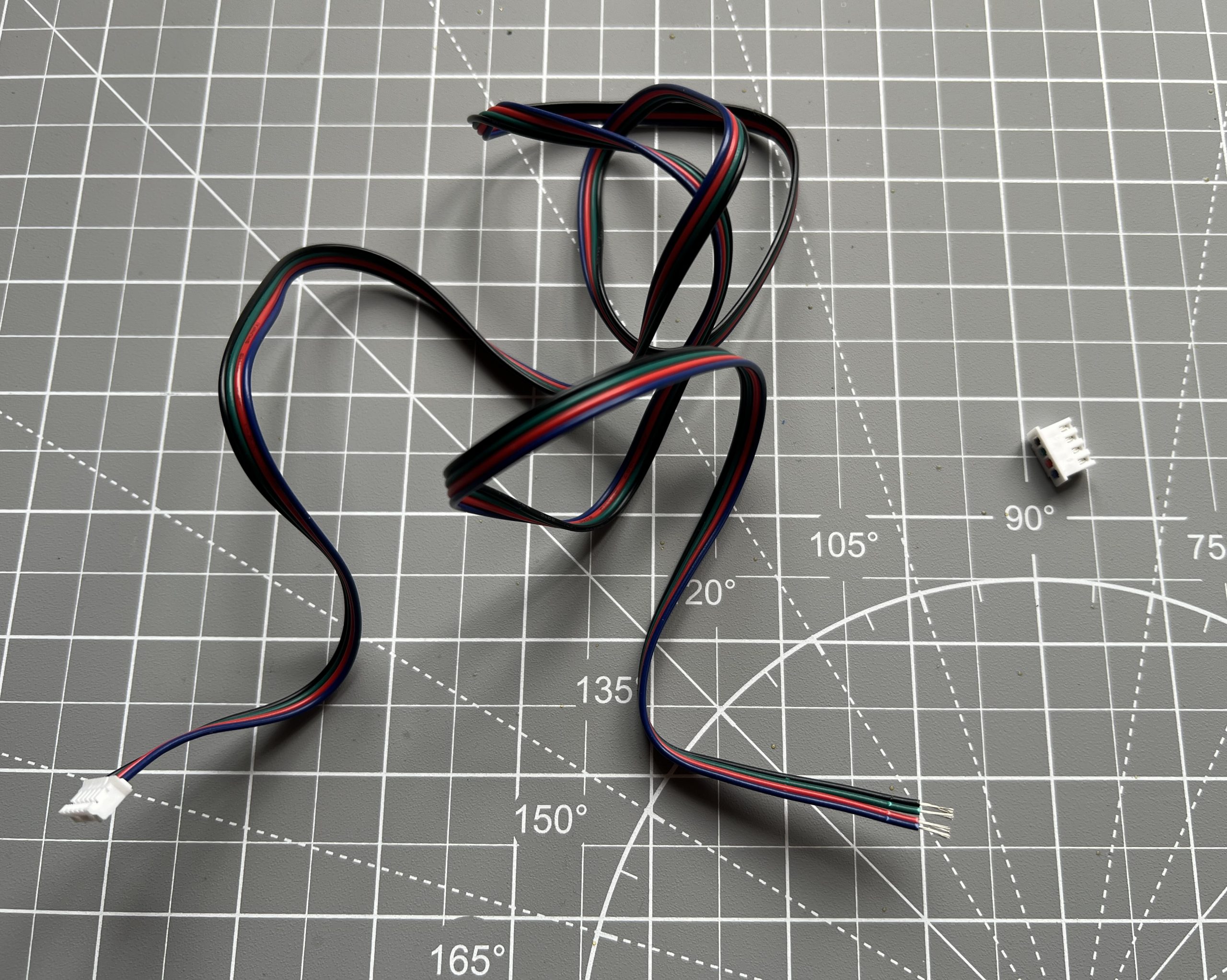
You guessed it, we solder them into our logic board. Be careful to have the right colors in the right order.

Stepper Motors
Parts
Stepper Motors x2
Pi Zero 2 W x1
Attach the proto bonnet to the Pi Zero 2 W. This is just headers and pins fitting together.
Plug in your stepper motors and, moment of truth, let’s power this up with the 12V power supply. We’re going to test the motors. You can add a piece of tape on the motor shafts to make it more visible when they move.

Once the “PlottyBot” wifi shows up, connect to it and point your browser to http://plottybot.local (or http://10.0.0.5 if this didn’t work). Scroll all the way down to the “Mechanics” section, and test each stepper in each direction, it should take 3200 steps to do a full 360° turn.

If your stepper motors are moving as expected, congratulations, you’ve done the hardest part! You can now create any machine that moves in 2 dimensions. If they don’t move as expected, check the next step 1.7 Setting the stepper driver’s Vref. If that doesn’t fix it, issues are very much case by case but in general: check each wire’s contact, check connection mapping, try to swap the motors.
Setting the stepper driver’s Vref
To run optimally, the stepper motor drivers need to be tuned to the motor they’re driving. The drivers have a tiny potentiometer that can be adjusted to do just that.
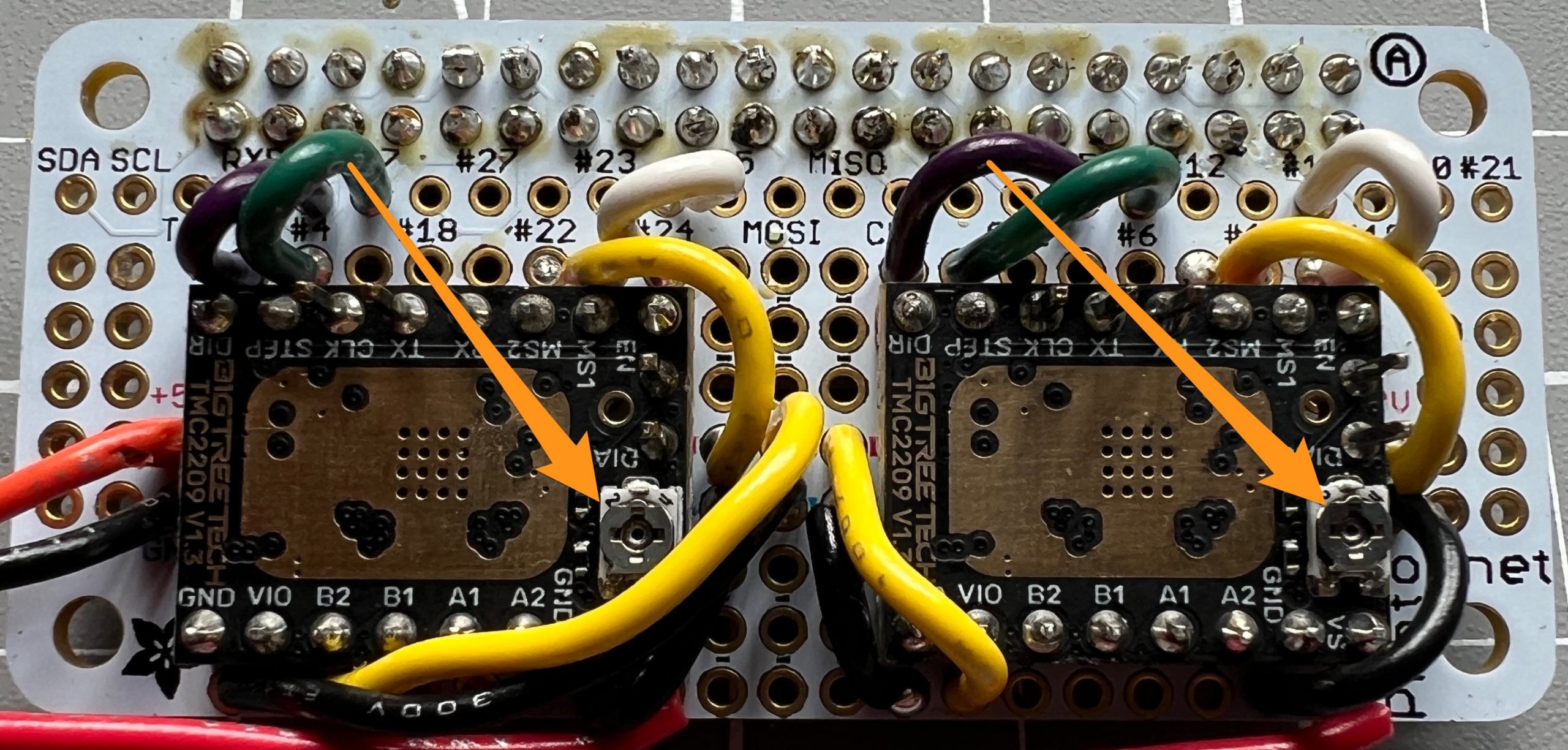
There’s a lot of information out there for setting Vref for your stepper drivers/motors, and I’m honestly a little confused about most of it, but our motors are rated for 1.5A, and this Vref calculator gives us a Vref of 1.2 for our driver. More importantly, I’ve got hundreds of hours of these drivers/motors running perfectly with this value.
Using you voltmeter in DC volt sensing, you want the ground probe on a ground somewhere in the circuit. I used the negative side of our power connector:
The positive probe of your voltmeter is then applied to the potentiometer of each stepper driver. Read the value and adjust the potentiometer with a small screwdriver until it reads 1.2V.
One trick you can do is to connect the positive probe of your voltmeter to the small screwdriver as such:
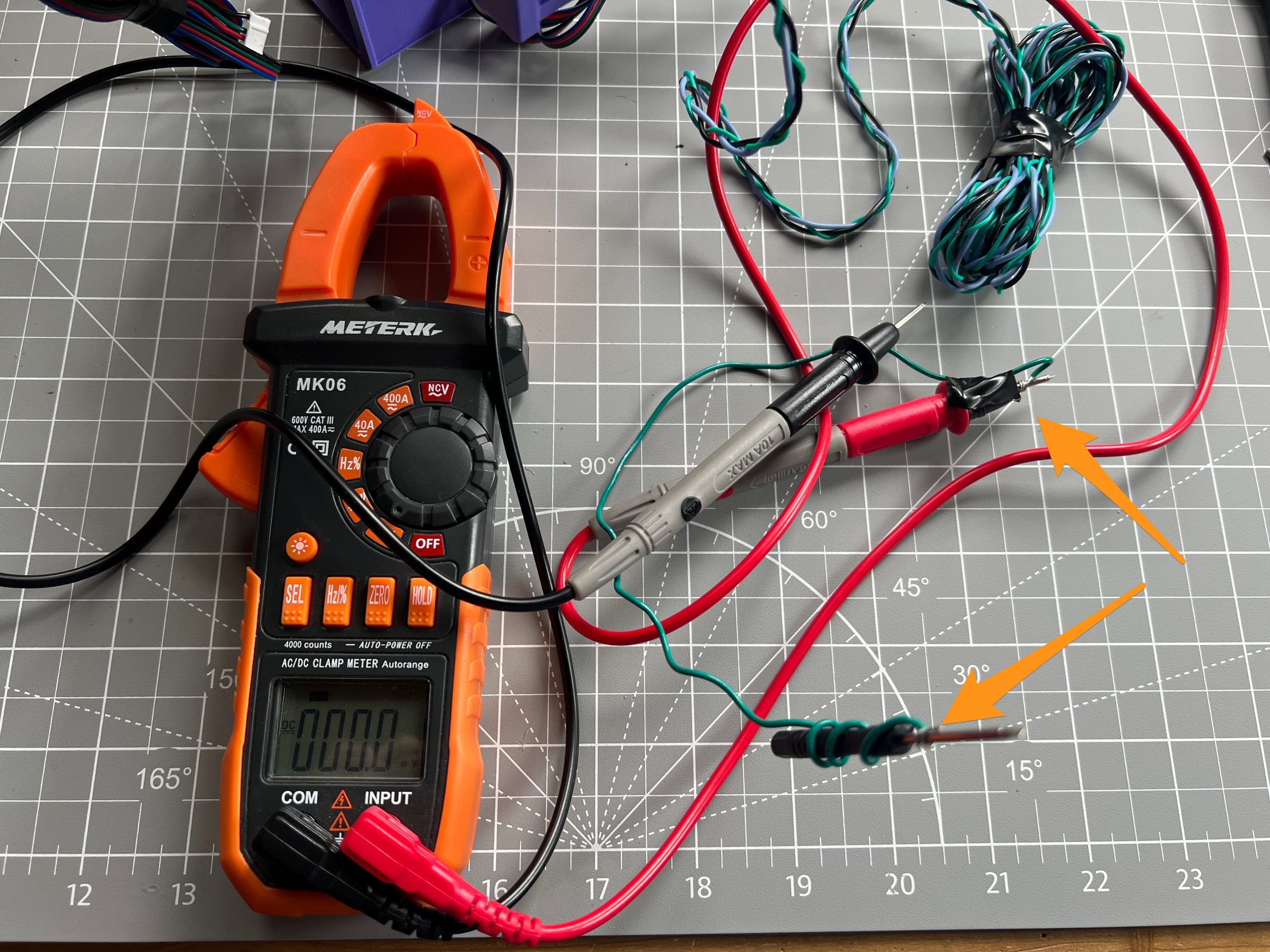
This way you can adjust the potentiometers and read the values at the same time. I unfortunately did not take a picture of the operation as it required both hands :). One holding the negative probe on a ground, and the other adjusting the potentiometer with the positive probe/screwdriver. More info and pictured can be found here if you need more visuals.
When you are done testing stepper motors & adjusting Vref, make sure to unplug power before moving on to the next steps. You can also unplug the stepper motors.
Servo Motor
Parts
Servo Motor
30AWG flexible wiring
3 pin male Dupont connector
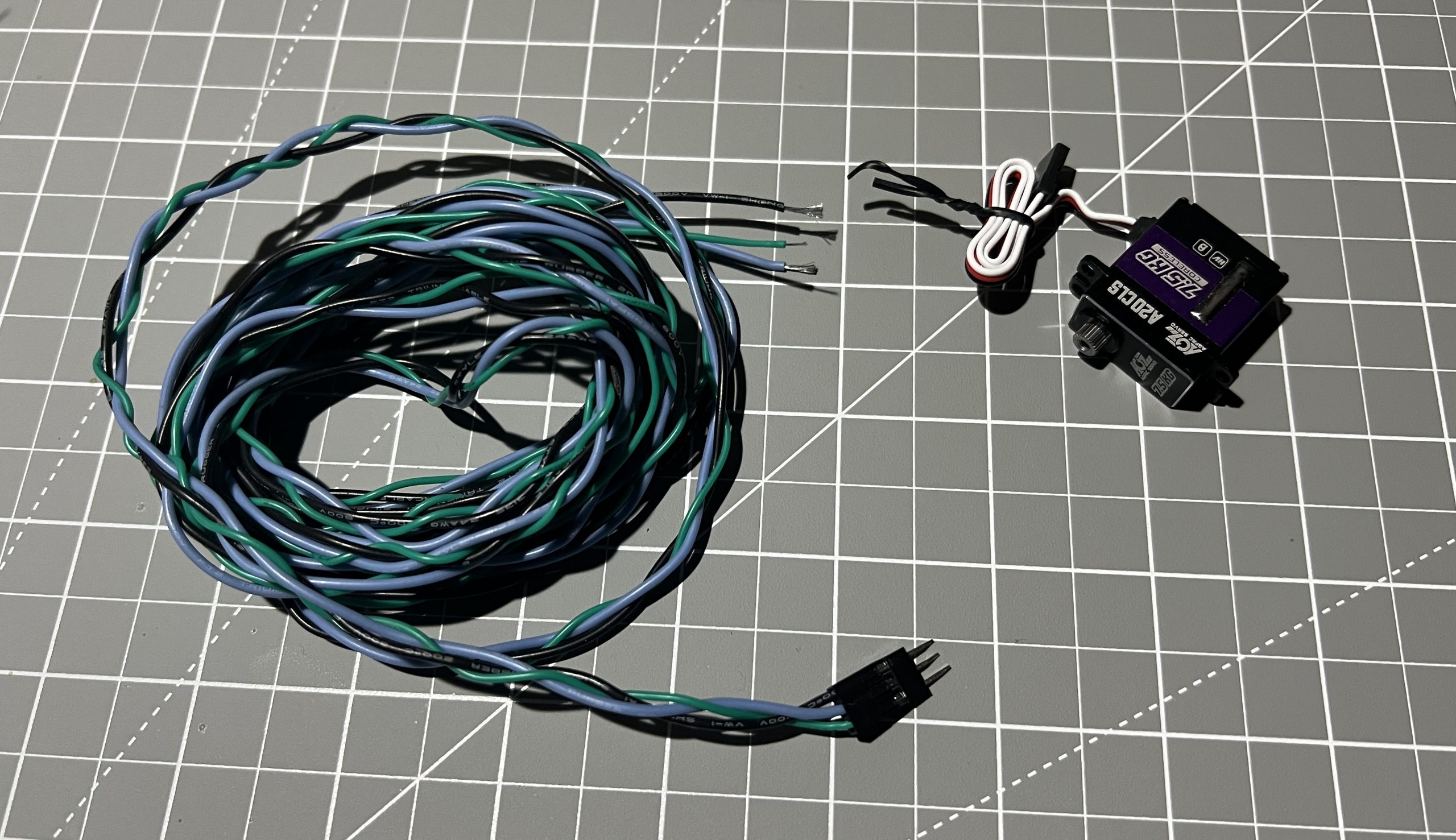
Give yourself a good length of 3 different colors or 30AWG flexible wiring. This is the wire that will travel from the logic box to the gondola.
It needs to be long enough to reach the bottom corners of your intended drawing area. To be future proof, it’s a good idea to make it significantly longer, and just bundle the extra in case you need it later. I’ve loosely braided the wires so they stay together. At one end, attach a 3 pin male Dupont connector. This will help us swap out Servo motors easily. If you bought the expensive A20CLS, they’ll go a long time before they die. If you are using cheaper servos like the SG90, they will die fast. On a long plot it’s a real pain and will waste time, fancy servos are worth every penny. MG90S will do pretty well but also die eventually.
The servo motor has a ground, power, and a signal wire. We solder the ground and wire into the 5V bus, which we extend by bridging it to nearby pins from the bus.
As with testing the stepper motors: power on the circuit, and hop on http://plottybot.local (or http://10.0.0.5) in the browser. The servo action can be tested with the “Pen Up” and “Pen Down” buttons.

We just added “tip action” to our 2D motion :). Make sure to power off the circuit before proceeding further.
Fan
Parts
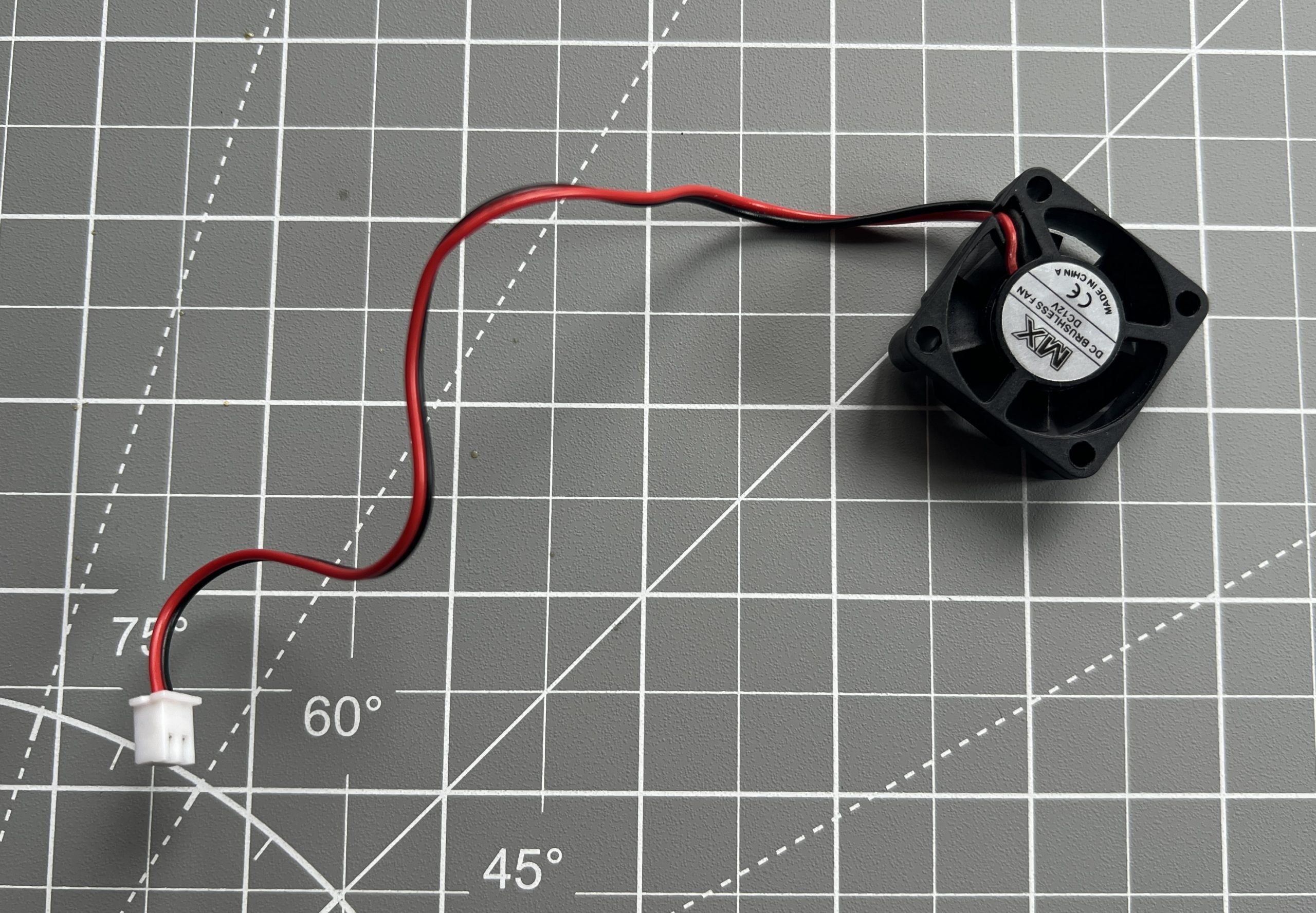
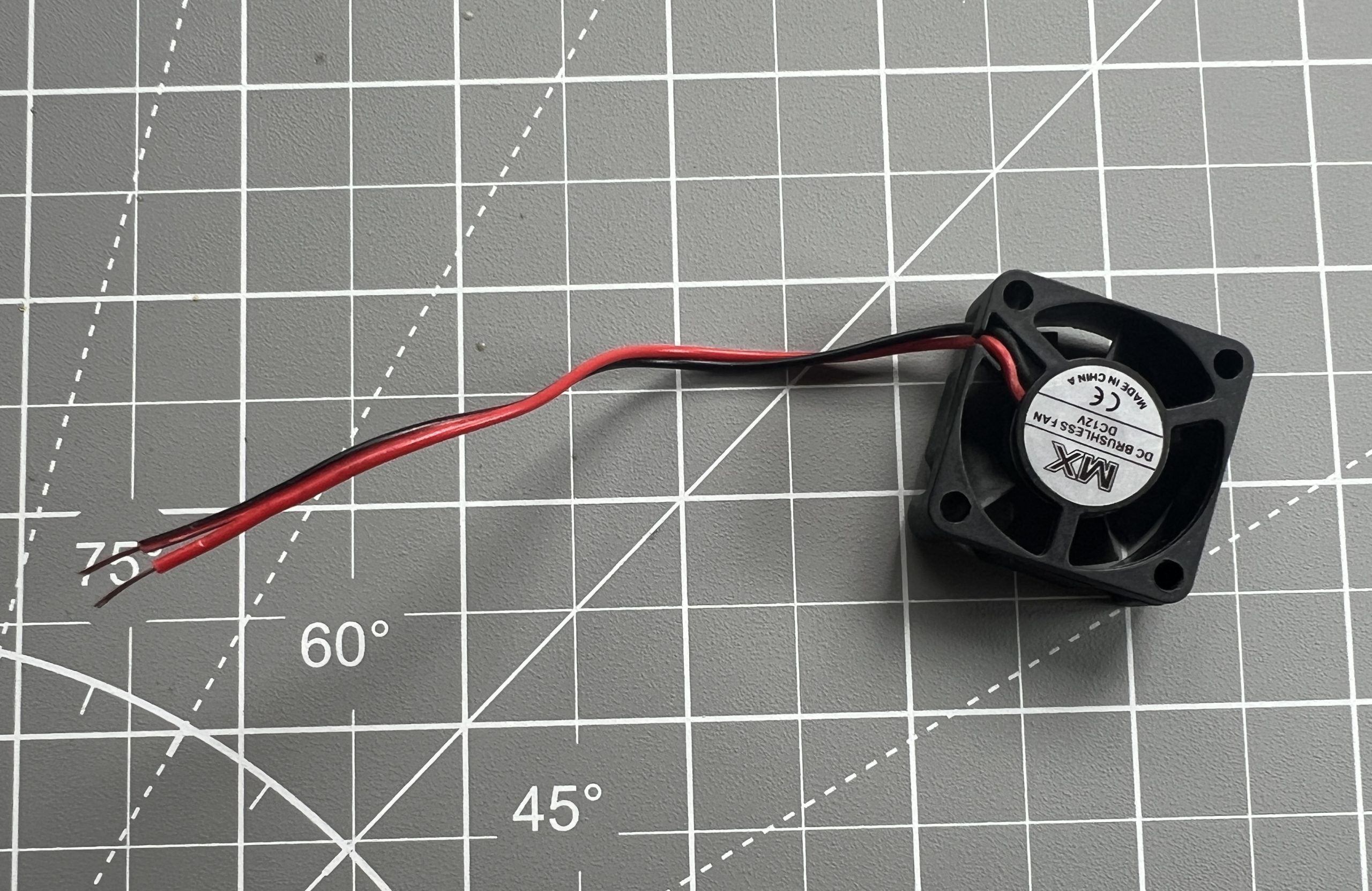
12V fan x1
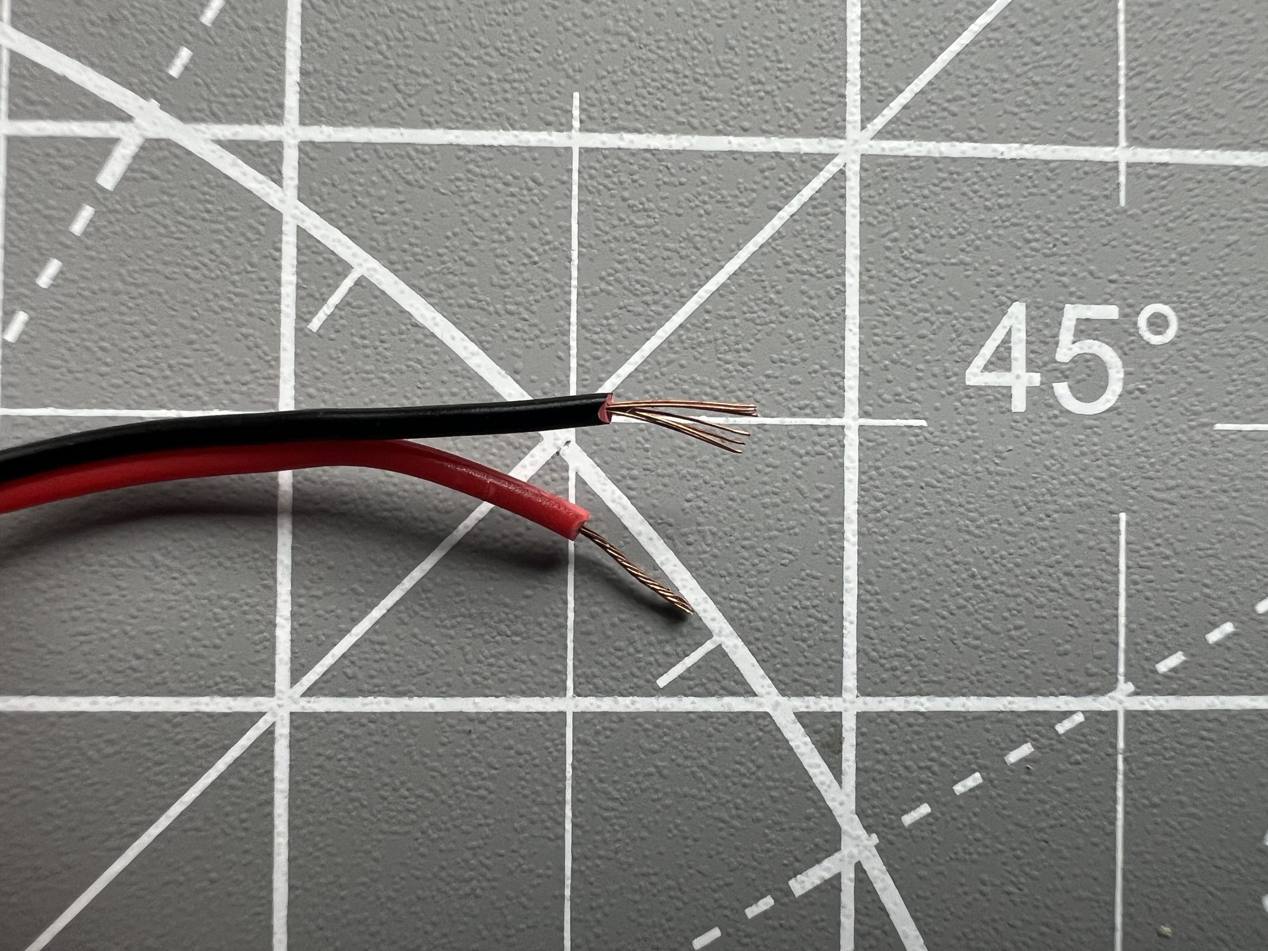
Grab the 12V fan, snip the connector, strip the wire, and twist the ends.
Add it to the now busy 12V power connector.
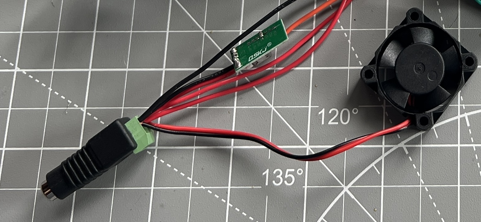
Anytime you power your circuit now, the fan will come on to help cool it.
It’s worth noting I have never found a nice quiet 12V fan in 30mm format. The one I have listed in the parts list isn’t great but it works. I found it noisy in my room and so I added another voltage regulator to it to make it run slower. If you have a recommendation for a nice fan in this format, please let me know. I think a a bit picky on fan noise, you might not object to hearing it, and you might not hear it at all depending on where you deploy your plotter.
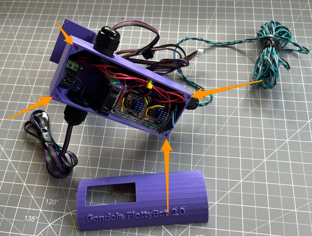
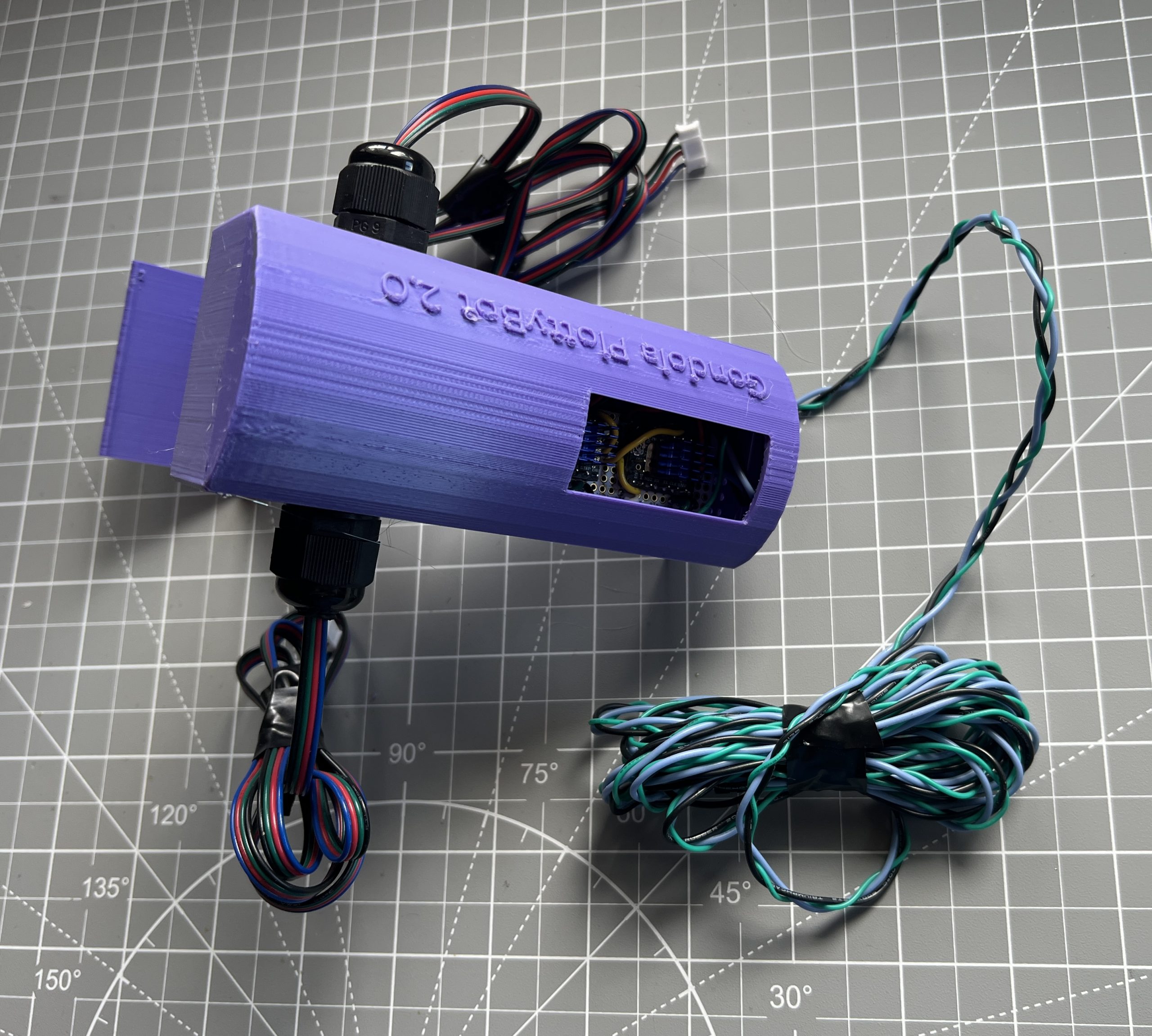
Building the Logic Box
Parts
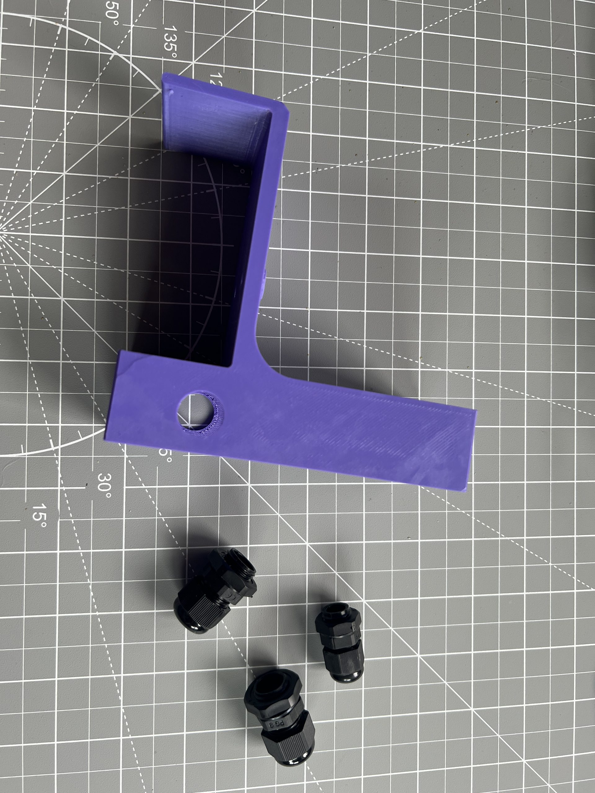
logix_box_x1.stl
logic_box_cover_x1.stl
Cable Glands PG9 x2
Cable Gland PG7 x1
Attach the glands to the logic box in the holes in which they fit.
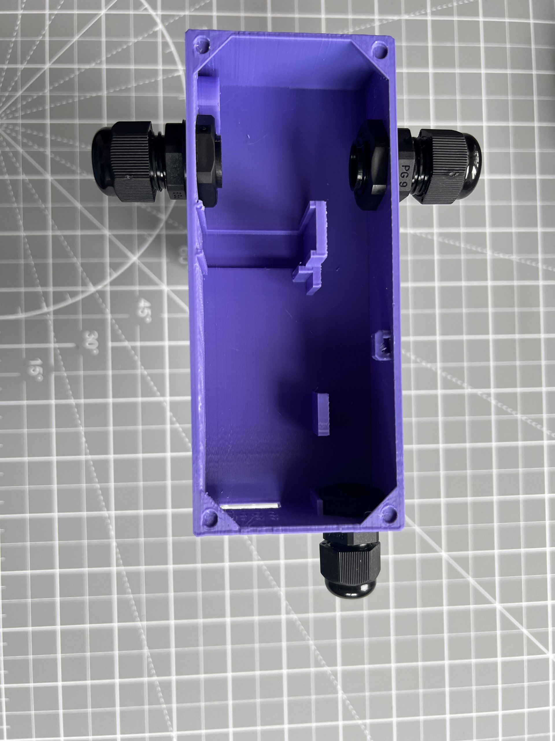
Run the wires for the stepper motors and for the servo motors through their respective glands. It helps to tied them up nicely after to help keep thing tidier.
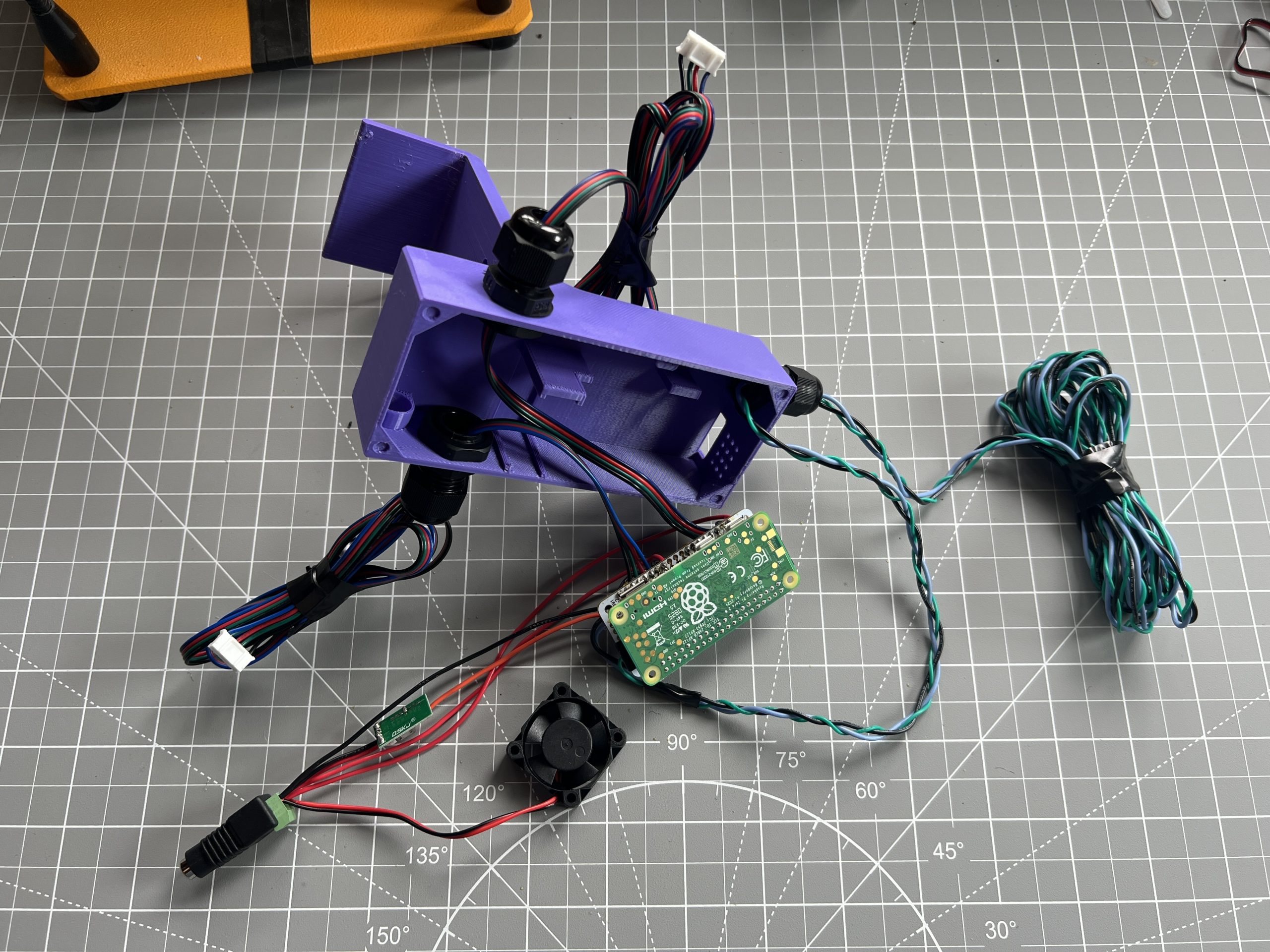
Taking your time and being very careful not to exert solders and connections too hard, install the various components of the circuit into the logic box.
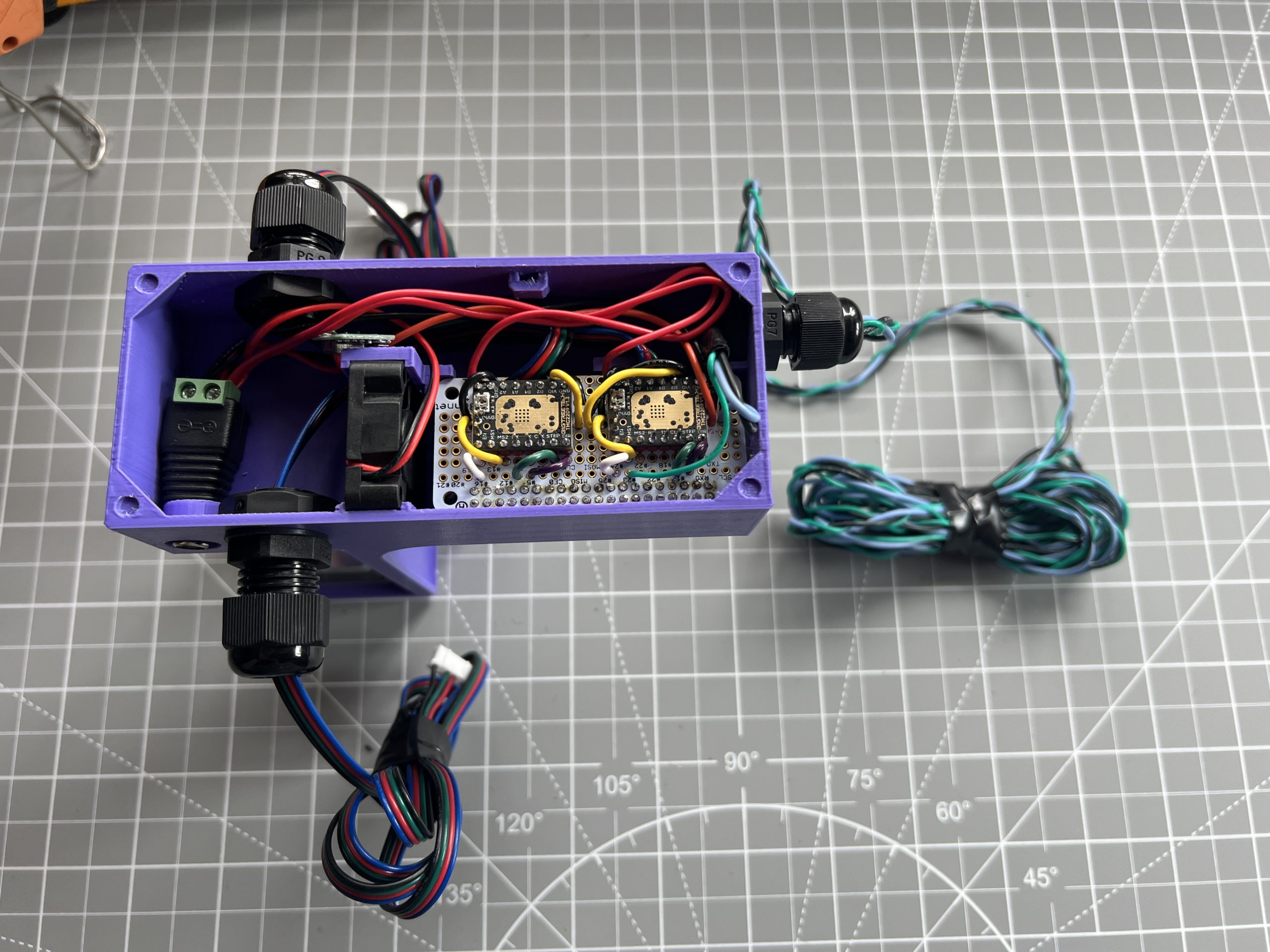
Apply little dabs of glue to keep things in place. There is no need to use too much glue, things should be pretty tight already, we just want to tack a corner or 2 in place. The only component I was generous with is the 12V power connector which will take pressure as we plug and unplug into it.
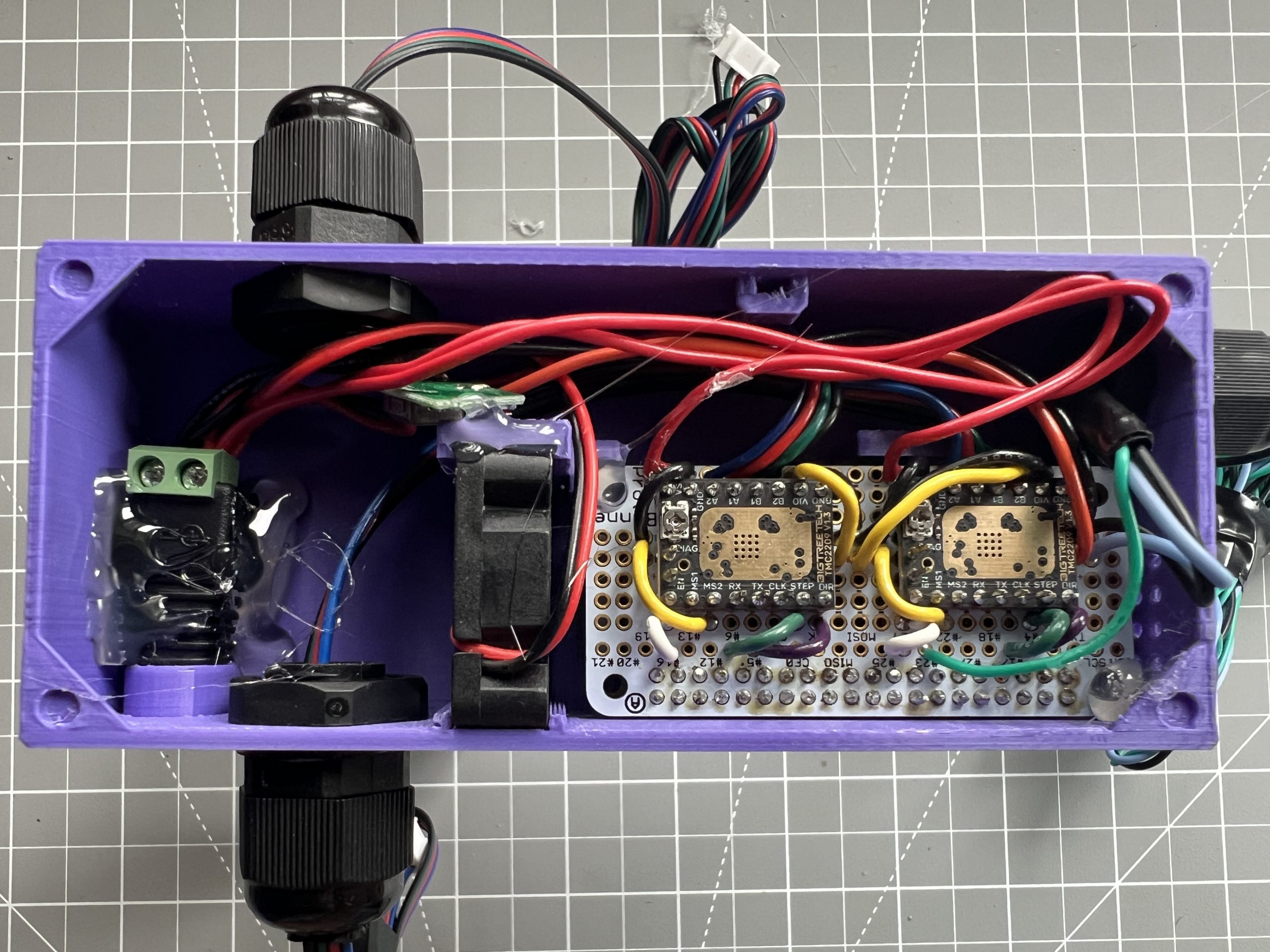
You can use zip ties to help manage wires.
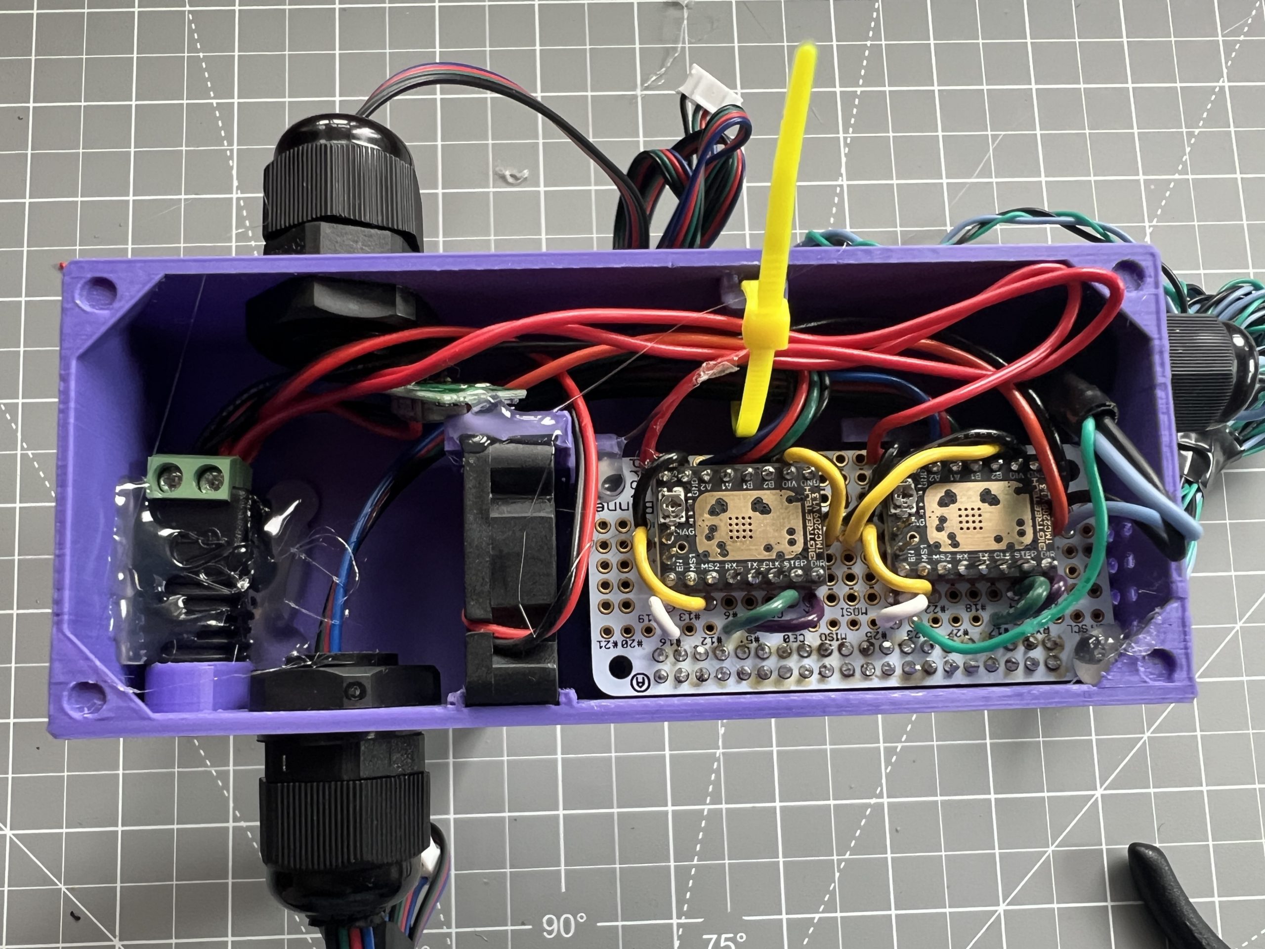
Lastly, you can tack glue the logic box cover at the 4 corners.
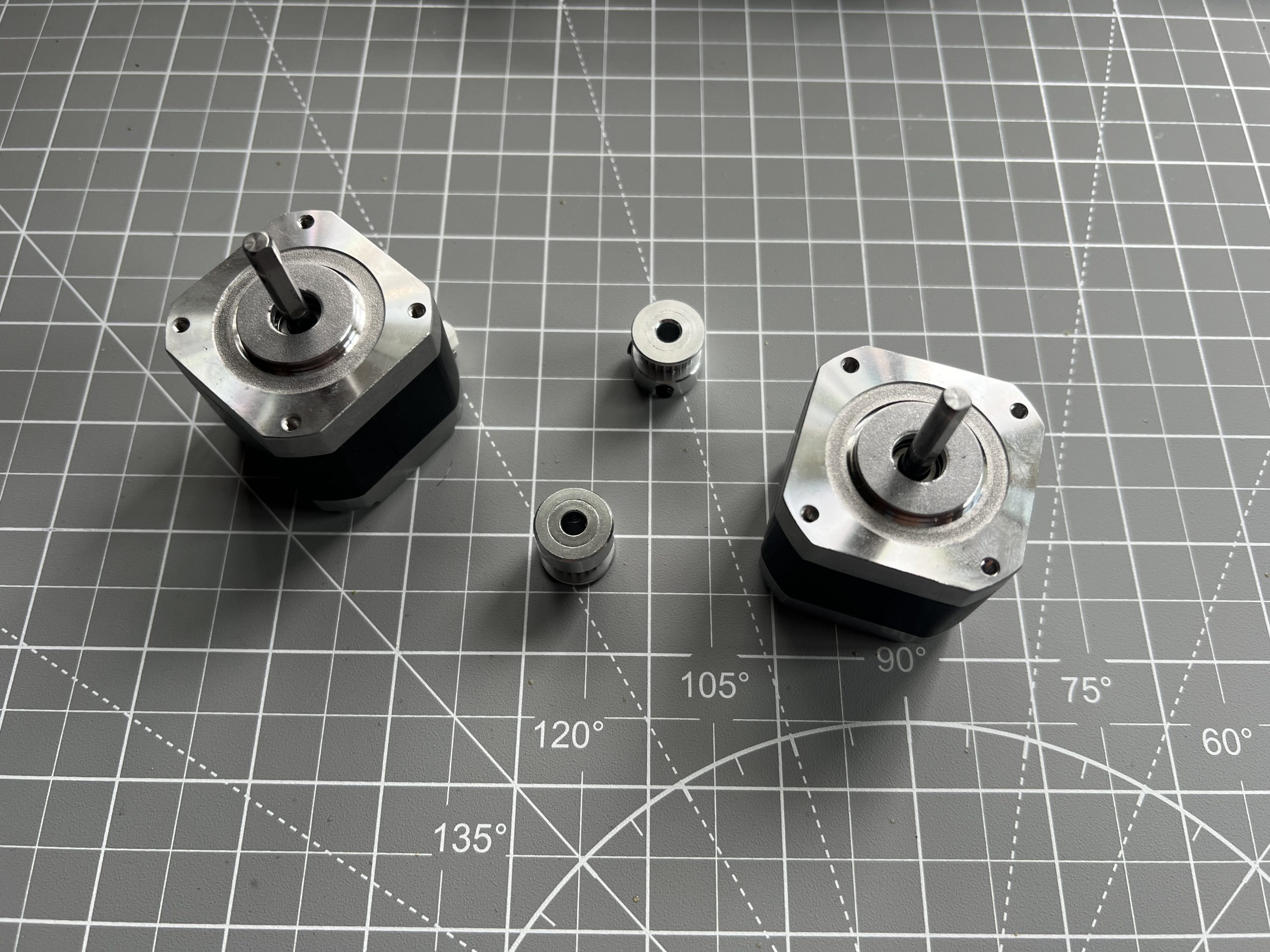
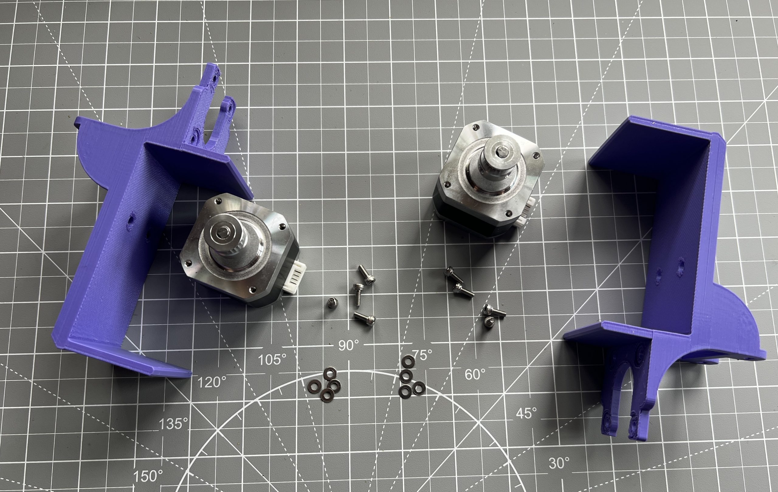
Stepper Motor Holders
Parts
motor_holder_x2.stl
Stepper Motors x2
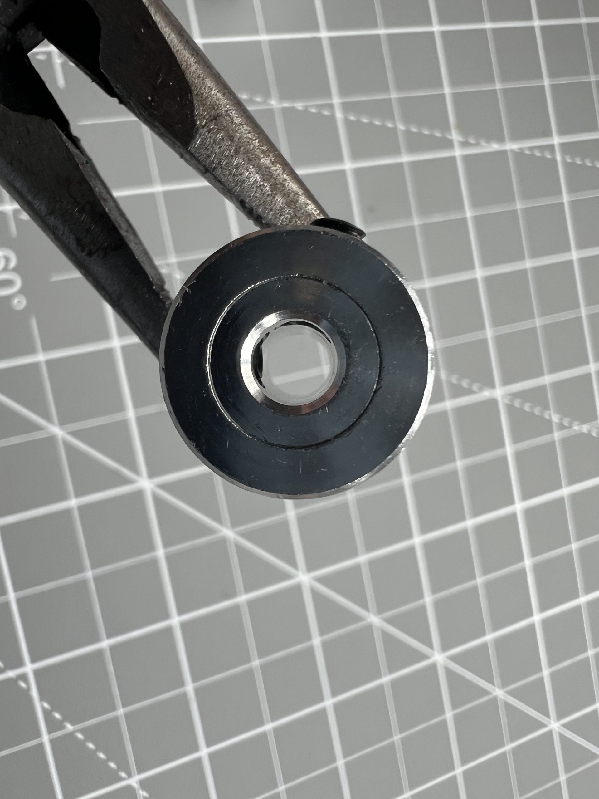
GT2 Timing Belt Pulley (20 teeth) x2
M3x8 hex socket screws x8
washers x8
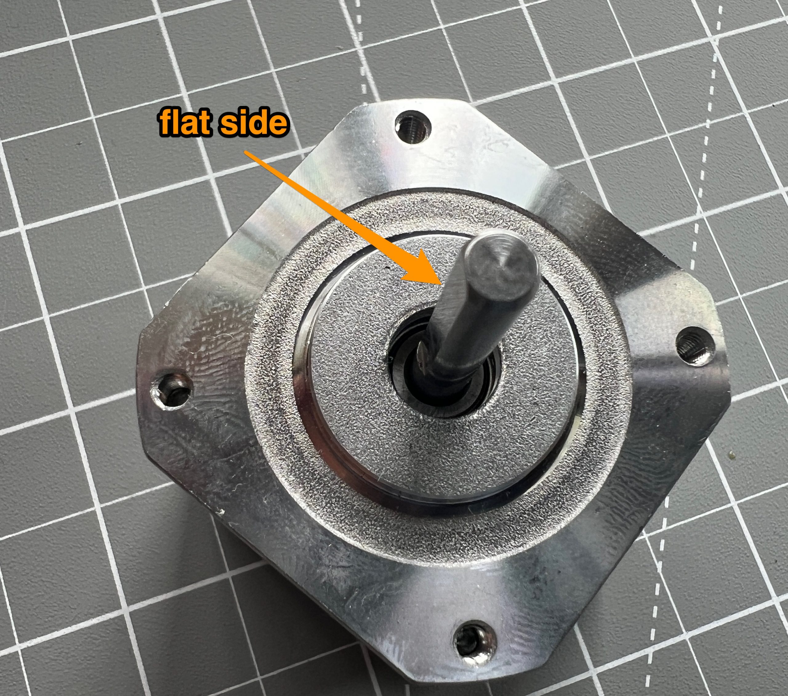
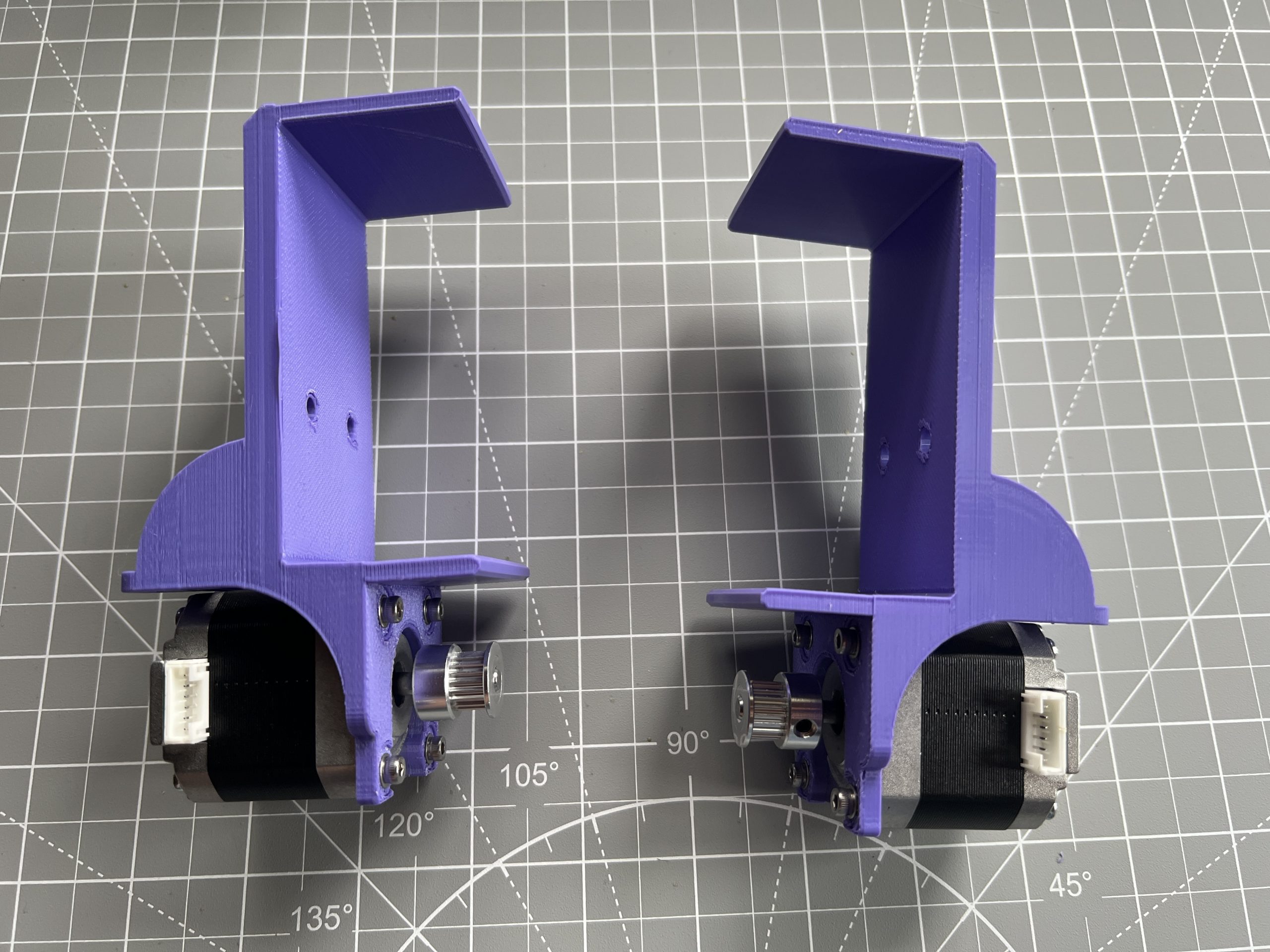
Attack the GT2 pulleys to the stepper motors shafts. Note the flat side of the shafts, make sure that one of the pulley’s tightening screws is lined up with it. Also note the orientation and top most position of the pulleys on the shafts.
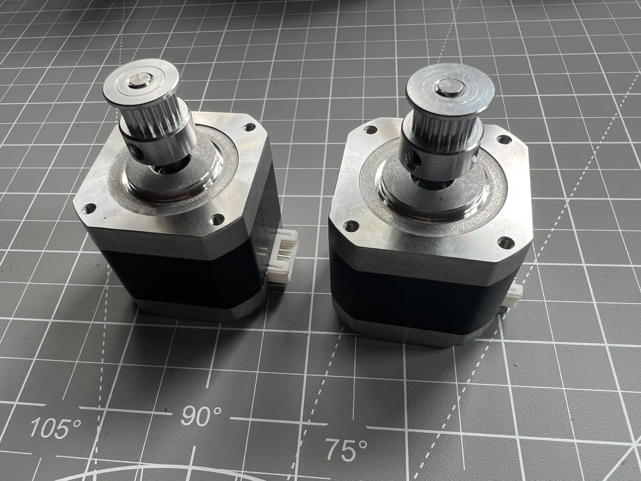
Faster the motors on the motor holders. Note the orientation of the stepper motors’ connectors. They should be mirrored as each will be on either side of the logic box.
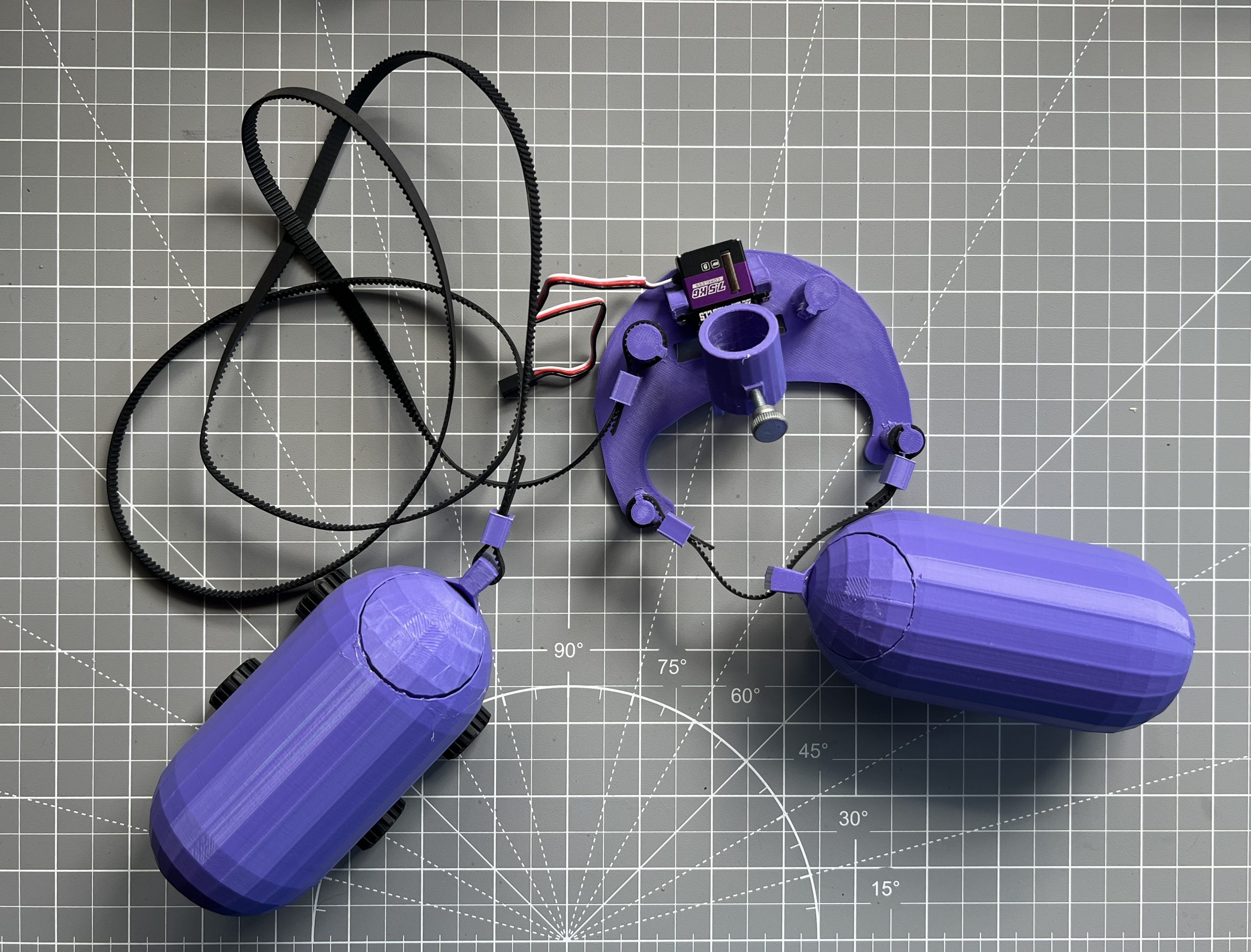
Gondola
Parts
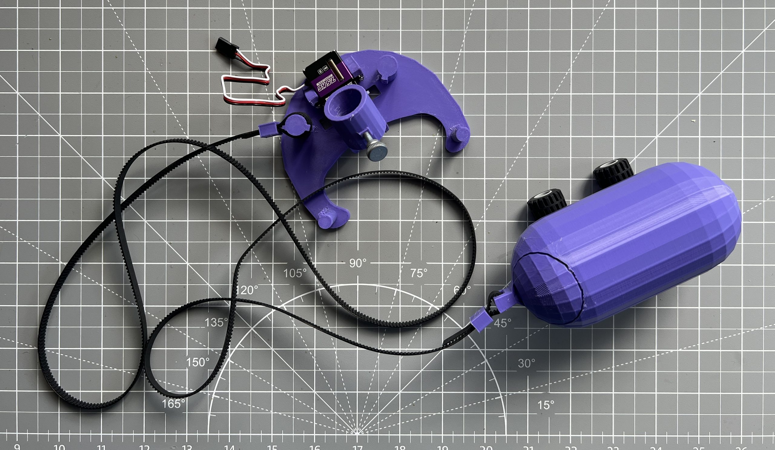
gondola_x1.stl
servo motor x1
M4x20 thumb screw bolt x1
M4 nut x1
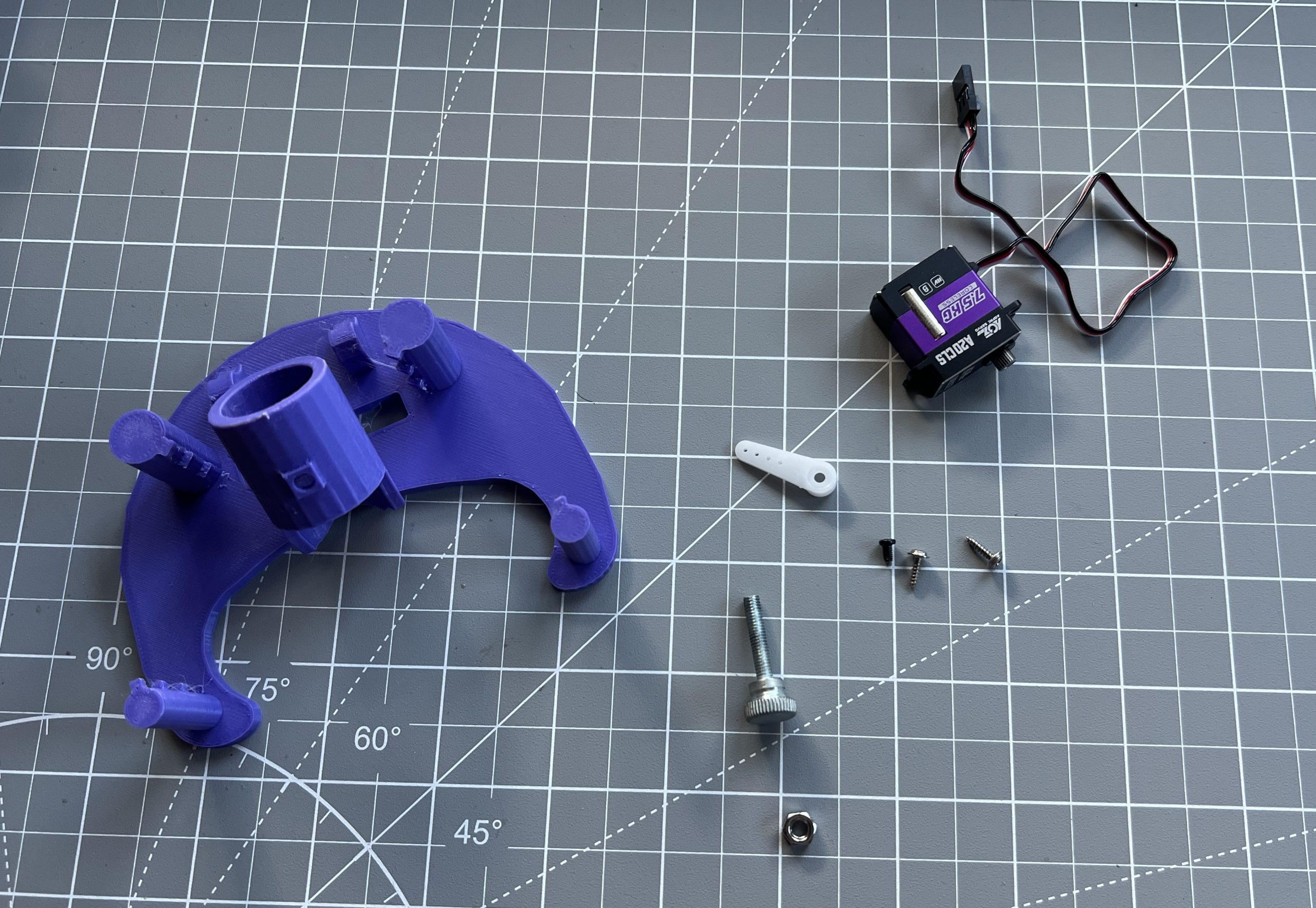
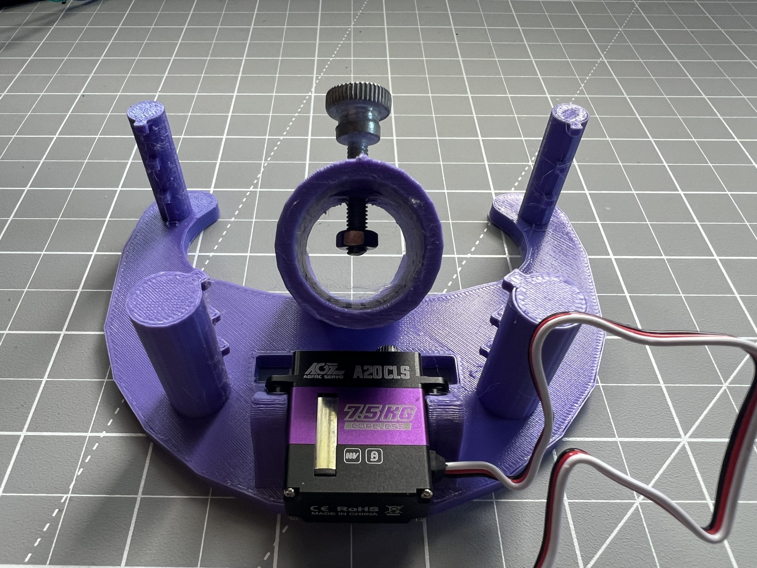
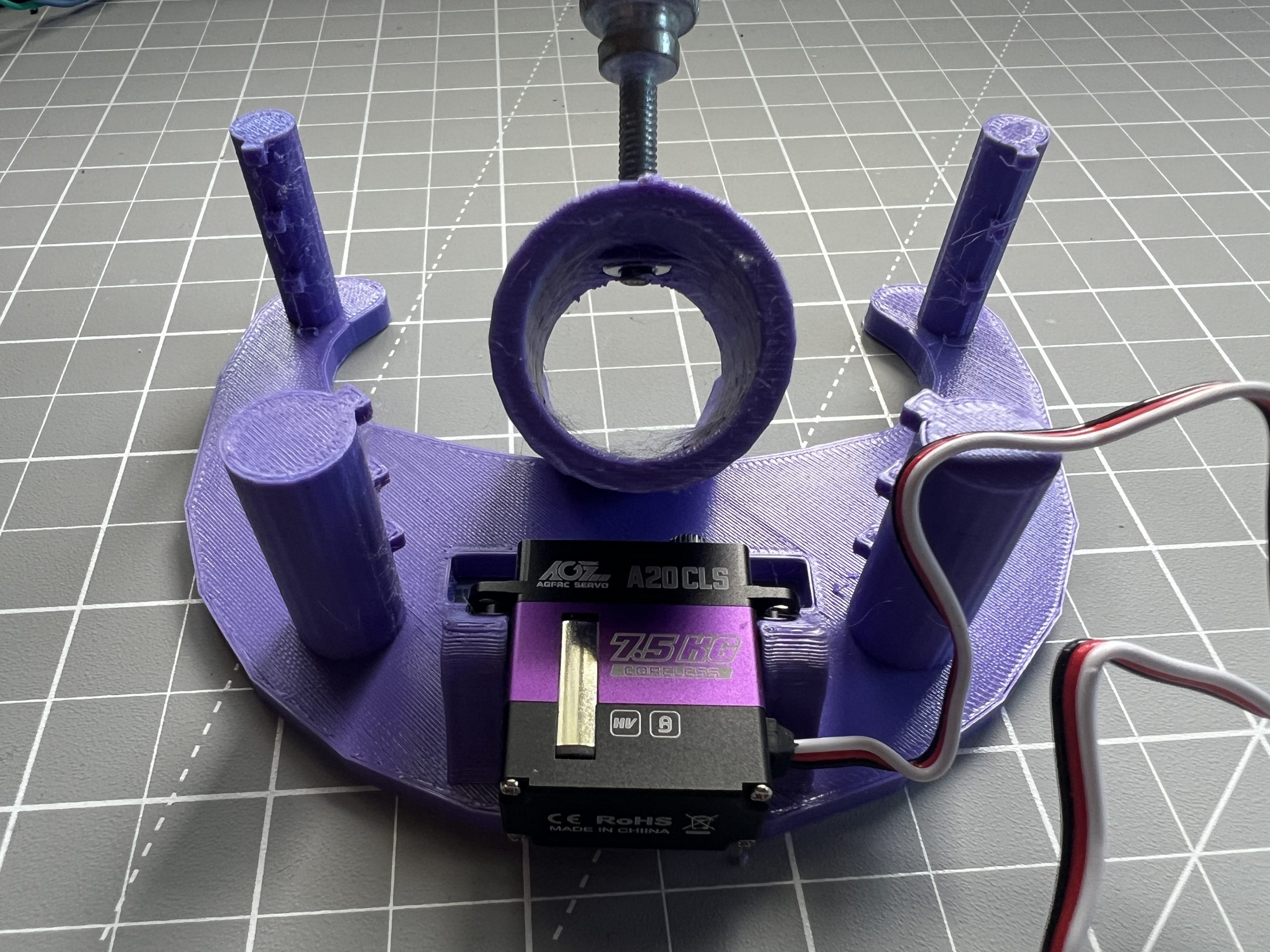
The servo motor should have come with it own screws. Use then to fasten it to the gondola. It is tricky to squeeze into position before attaching with the screws, I swear it’ll go in :).
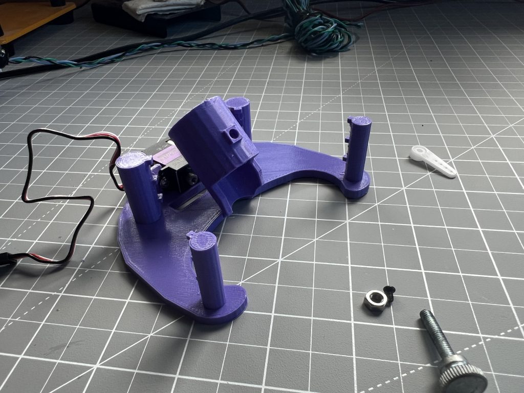
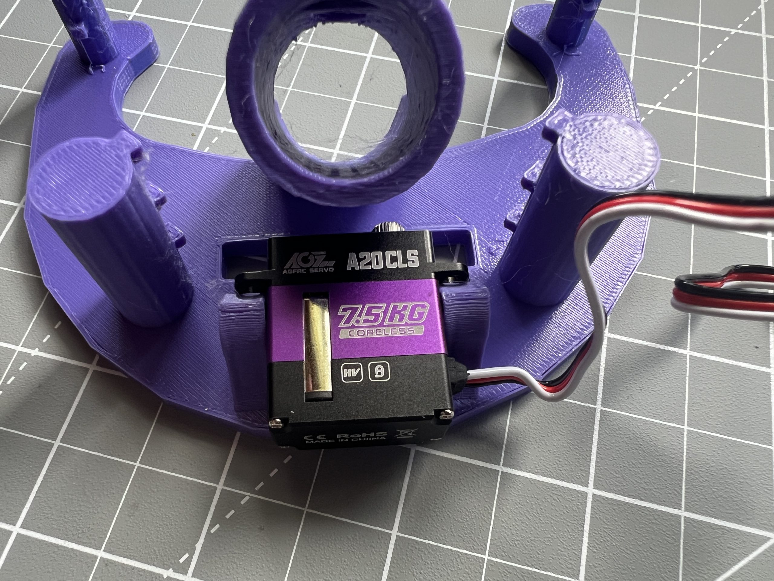
Put the thumb screw bolt through the hole, add the M4 nut, and use the thumb screw bolt to pull the M4 nut into its seating. This is a pressure fit.
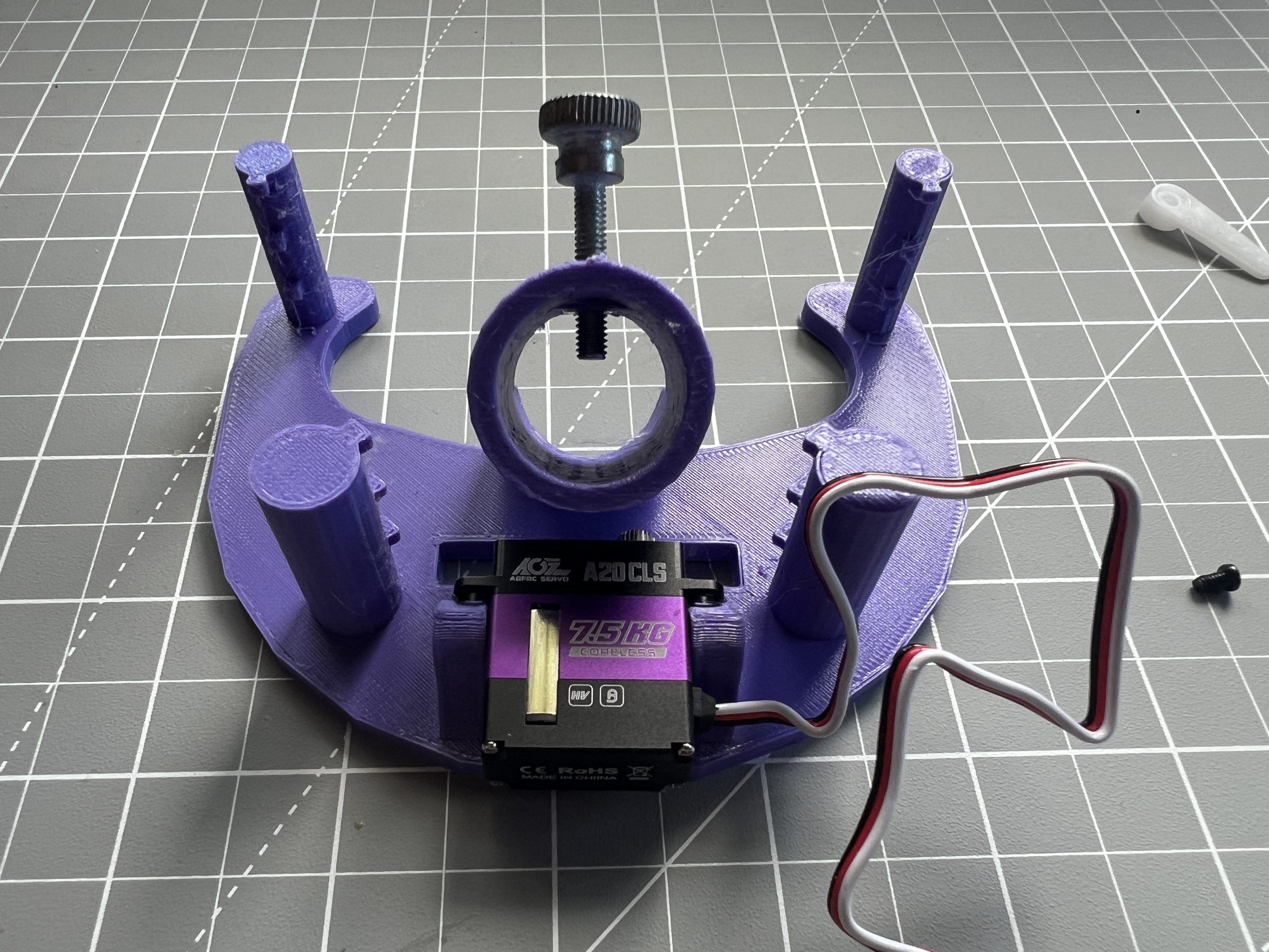
Plug the servo into the circuit using its connector, power on the circuit, hop into the web interface and down to the “Mechanics” section. Click on the “Pen Down” button. When the servo it into the “Pen Down” position, attach the servo’s arm such that it is running along it, it should not go through the gondola. Once the arm attached, hit the “Pen Up” button and make sure that the arm now pushes the gondola away from the desk. You might need to adjust the servo’s range of motion with the pen_down_pulse_width & pen_up_pulse_width settings in the Mechanics sections, but hopefully the defaults just work.
Make sure to power off the circuit when done testing.
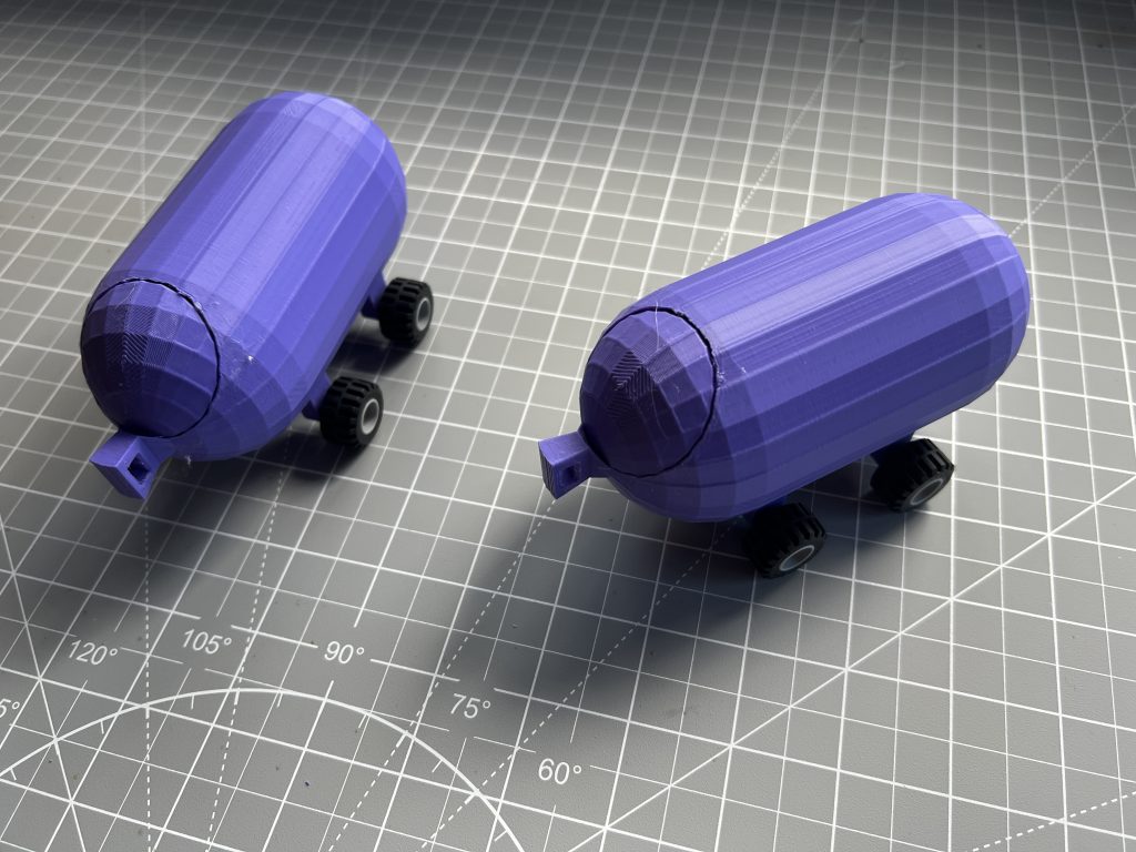
Weights
Parts
side_weigth_x2.stl
gondola_weight_x1.st
weight_cap_x3.stl
lego wheels x8
a bunch of dead weight, old batteries,misc. hardware, et cetera.
Attach the lego wheels to the 2 side weights, and load them with some mass. Make sure they weight the same. The gondola weight can be a little heavier than the other 2. I can’t tell you exactly how many grams to add, this largely depends on the size of your deployment. Because of this, it might not be the best time to glue the weight caps on, maybe keep them open for now until you’ve installed the plotter on a wall. When you have added enough mass to them that the belts are straight in all positions, it’s safe to close them.

Belts & Deployment
Parts
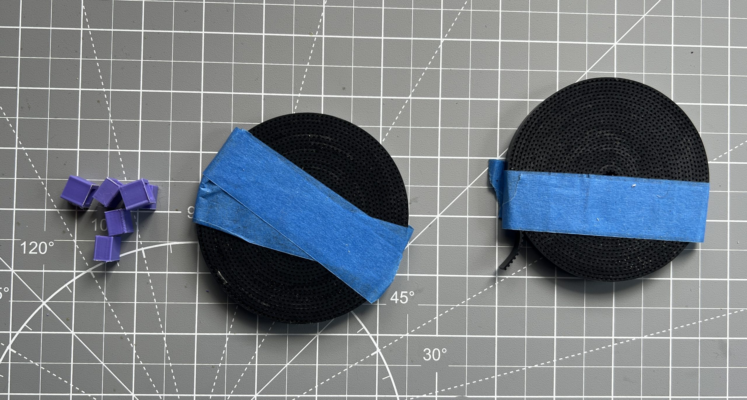
belt_looper_x4.stl
2×4 piece of lumber, the length of which depends on how big you want the drawing surface to be
GT2 timing belt
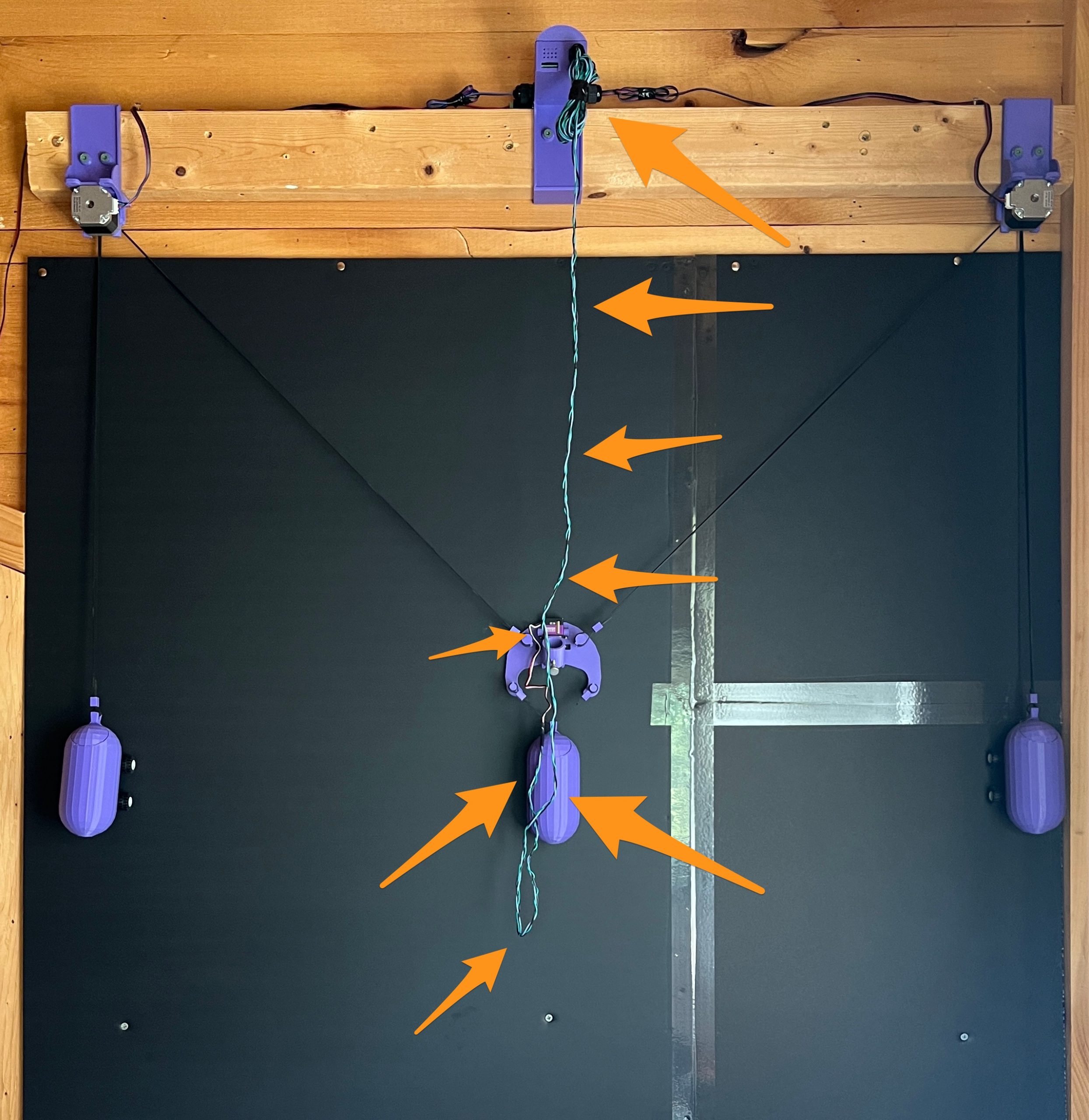
Fasten the logic box and motor holders to your piece of lumber, which you can attach to a wall.
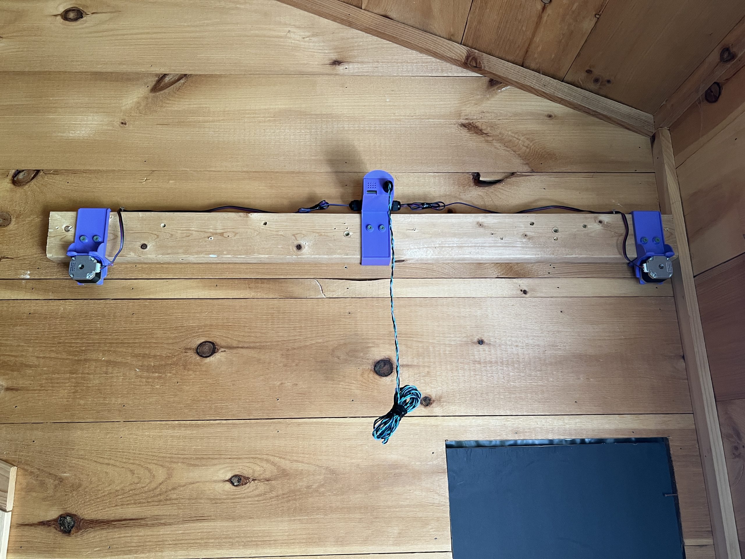
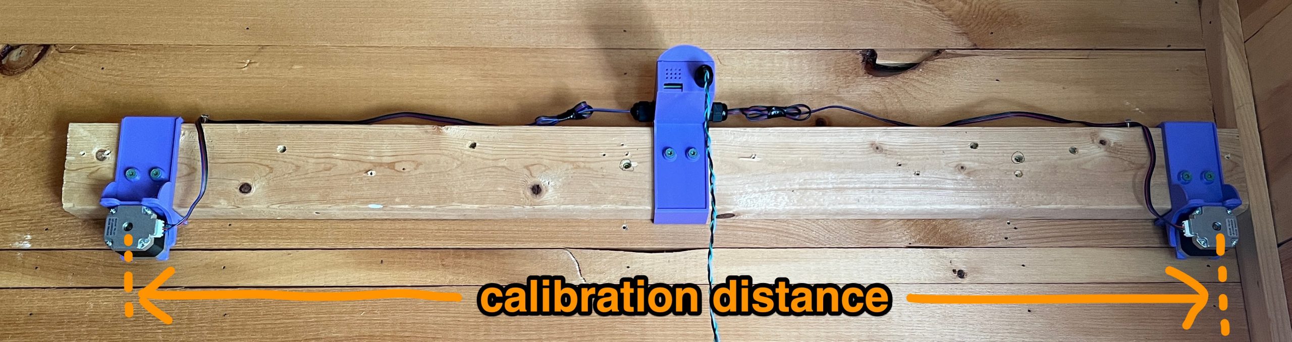
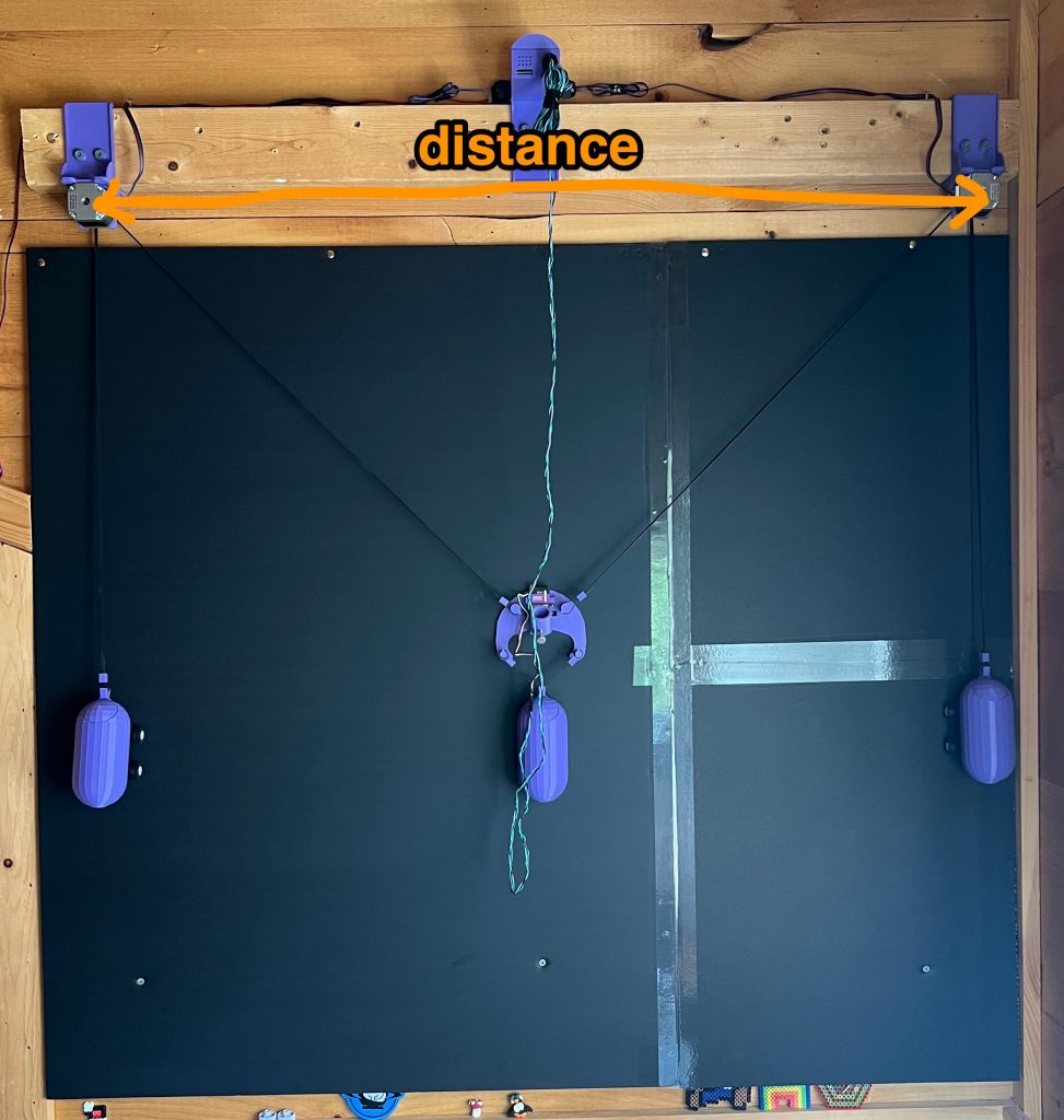
Measure precisely the distance in centimeters between the centers of both motors. This is the only thing needed to calibrate the plotter, all the math is derived from this distance. And so if you keep the machine on the same piece of lumber, you don’t need to measure this every time.
Grab you GT2 belts and belt loopers. Attach the gondola’s weight and a single side weight as bellow. Think of where the belt’s “teeth” are facing. Also unless you have a precise idea of the machine’s range of motion, you might want to leave a decent amount of extra belt slack to make adjustments later. Later when you are happy with everything you can trim it.
Hang the belt around one of the stepper motor’s pulley.
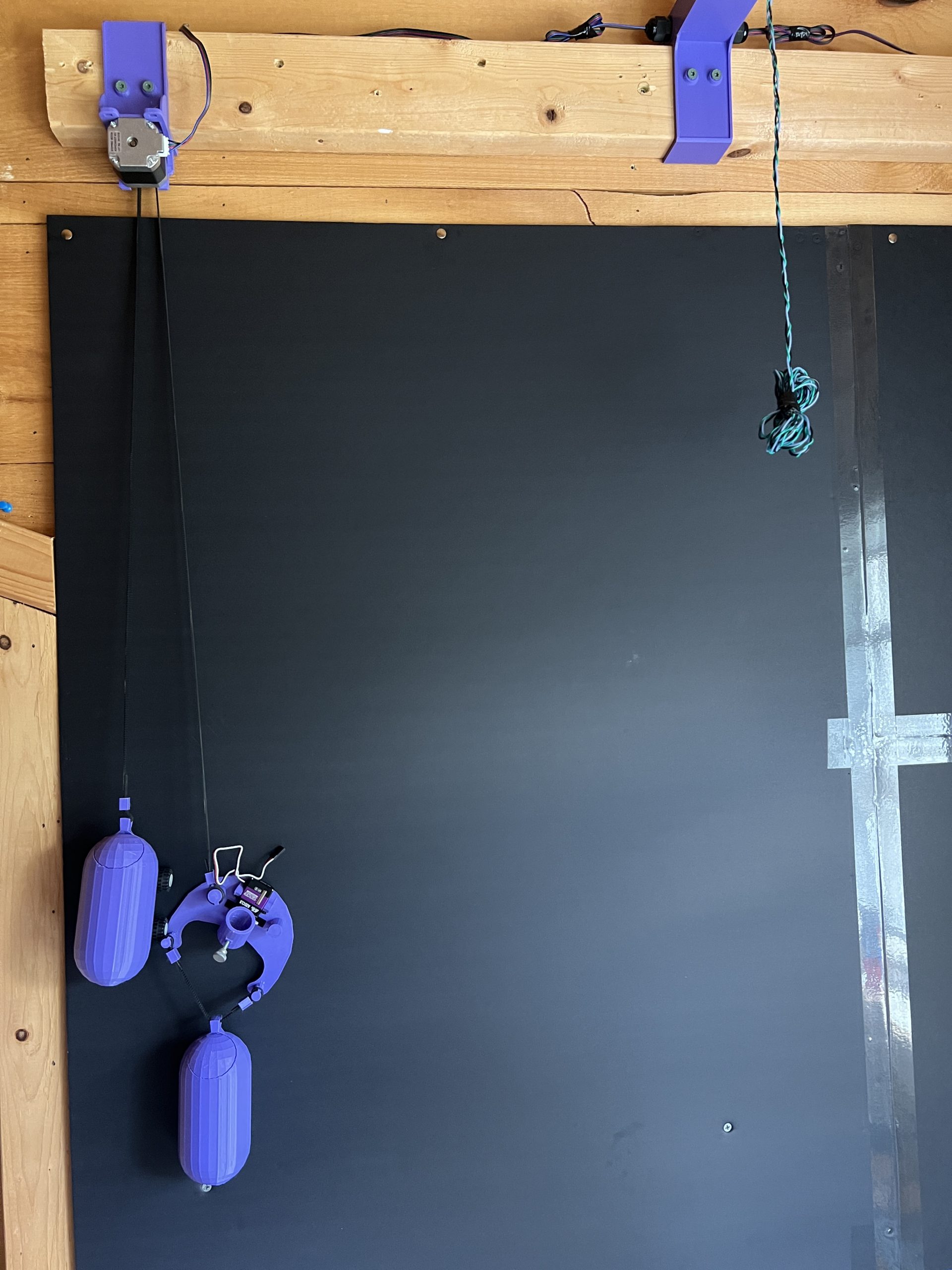
Now do the remaining motor weight, hang it on the other stepper motor, and join it to the gondola. This operation requires 3 hands :).
Lastly, connect the servo motor:
Congratulations, your Gondola Plotter is ready :).
Usage
Plotter Code
The plotter instructions (Plotter Code section in the web interface) are all normalized on a (X,Y) coordinate system going from 0 to 100. It doesn’t matter how big or small your plotter it, the instructions will always be from 0 to 100 on both axes.

The main instructions you can give it are as follows:
go_to(x, y)
pen_down()
pen_up()
Simple eh? You can go pretty far with lots of these.
There also exits a few special instructions:
color( #888888 )
pause()
The color( #hex ) instruction won’t swap the pen for you, but it will be used in the preview, and it will pause the drawing at that point and ask for the pen swap in the web interface.
The pause() instruction will just pause the drawing for you, which you can resume in the web interface.
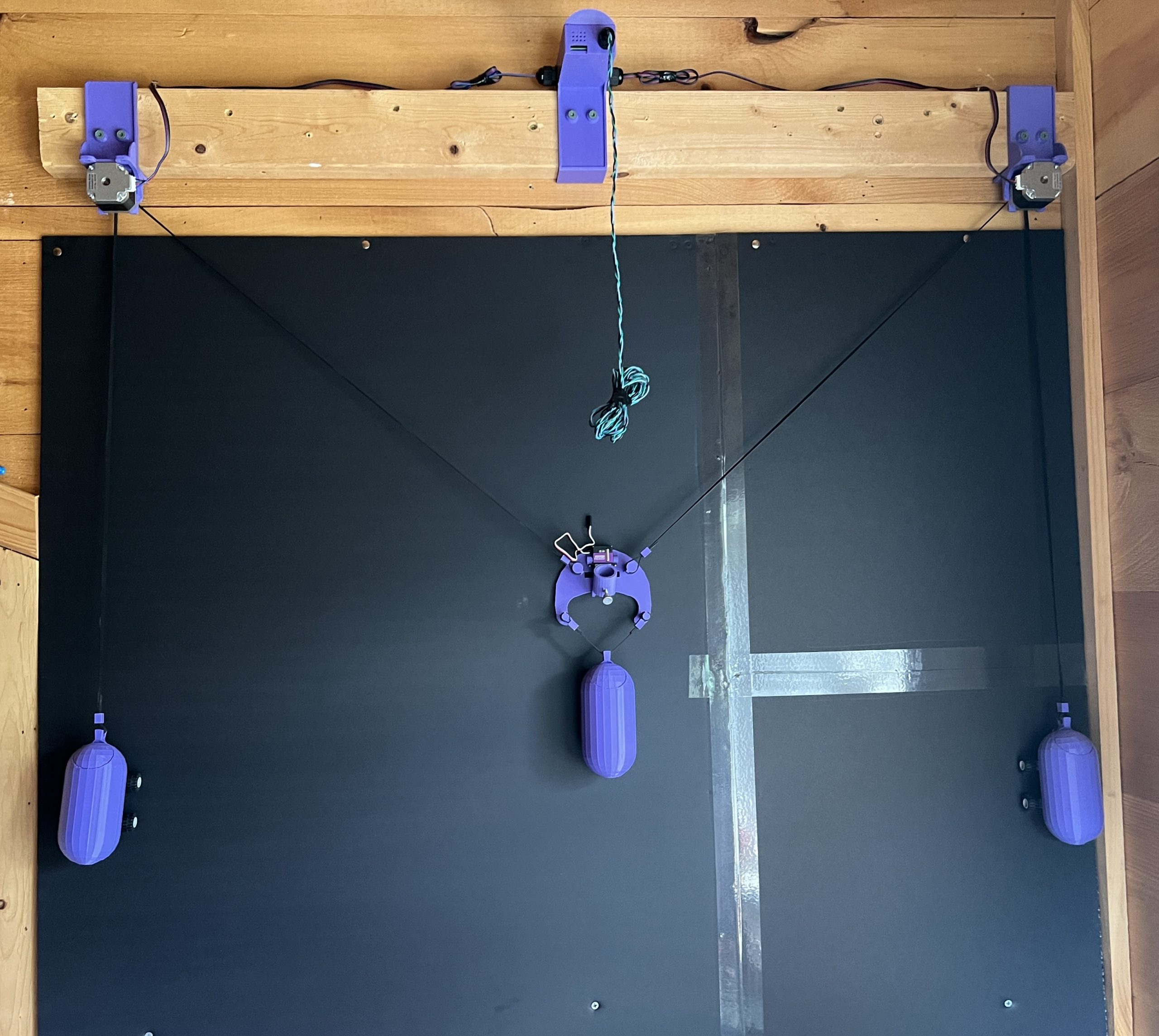
Calibration
When you deploy the plotter
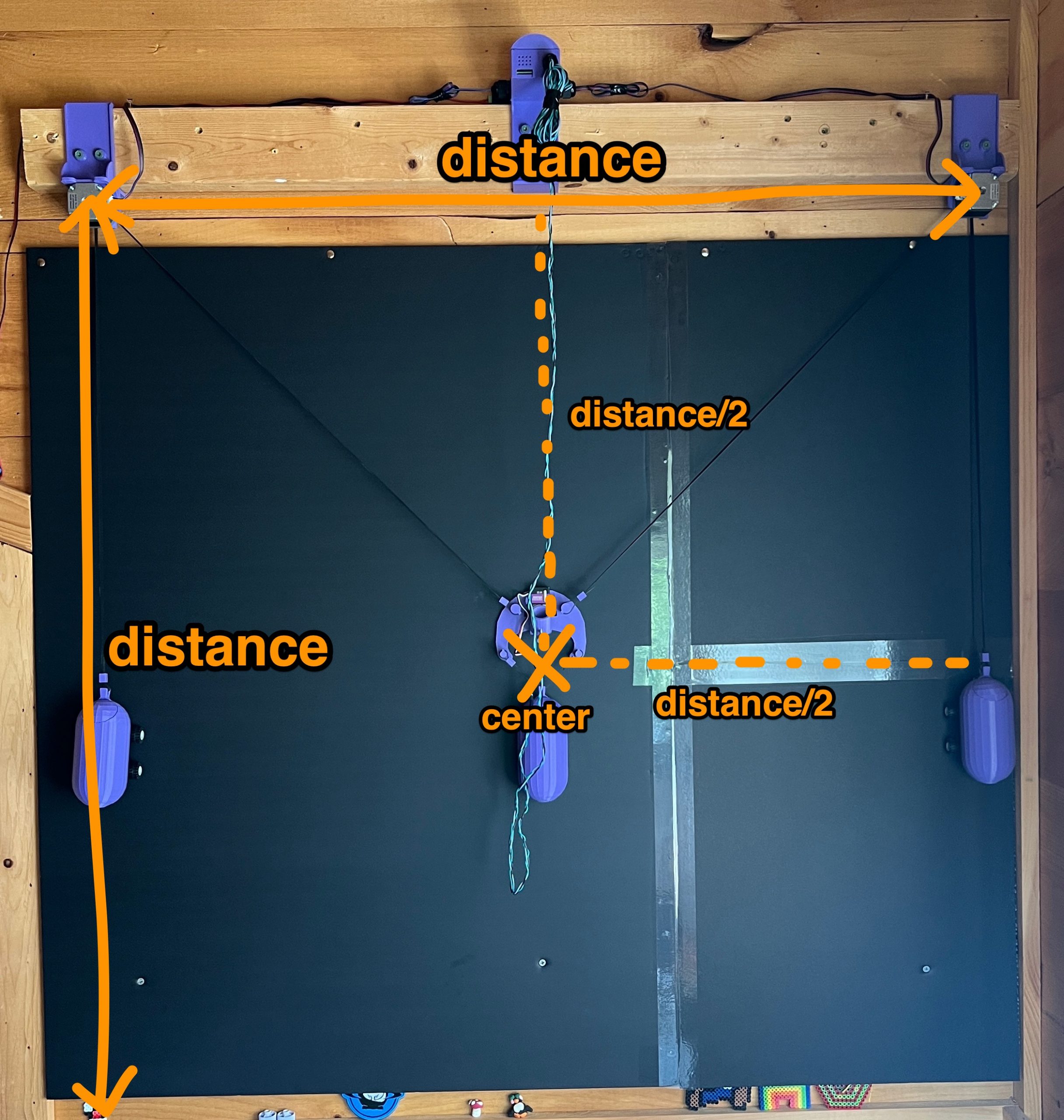
Measure the distance between the centers of your 2 stepper motors. That is the calibration distance the plotter asks for before doing anything. It’ll remember it so as long as you don’t change where the motors are, this is a one time thing.
Make sure that you have enough belt length to cover all the extreme points of the drawing surface. There’s some math to figuring out what that length is, but I’ve never had issue just eyeballing it and adjusting a little.
The best way to make sure everything will work (enough belt, weights don’t do too or too high, belts don’t sag), run code for a simple square 0->100 square that will take the gondola through all extreme positions.
go_to(0,0)
pen_down()
go_to(0,100)
go_to(100,100)
go_to(100,0)
go_to(0,0)
pen_up()
go_to(50,50)
To run this, you need to power on the plotter, and thus follow the calibration for that (give it the distance, and start in the center).
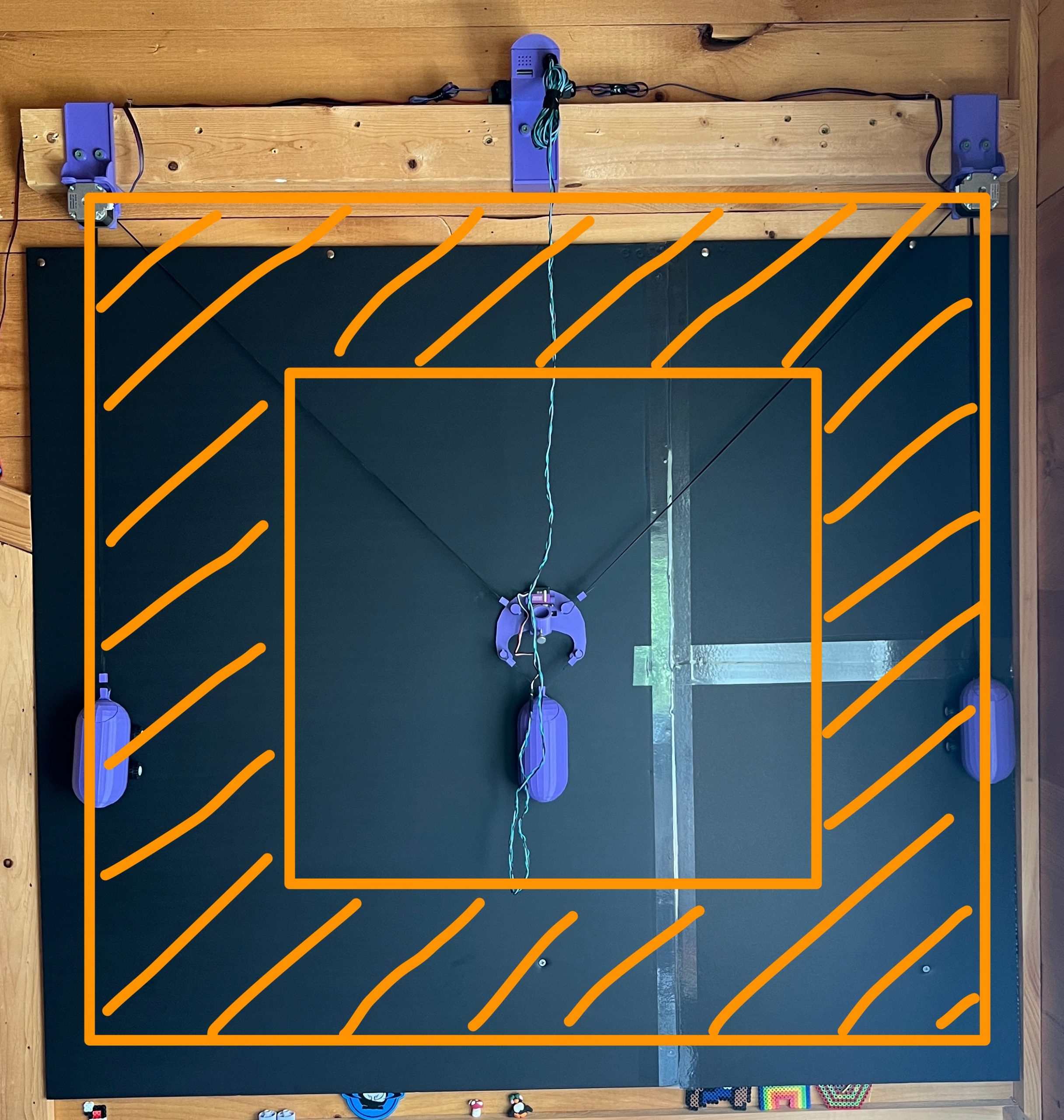
You cannot reach the extremest of extremes. The plotter has a built in 20% margin on all sides because some gondola positions are untenable by the hardware. This is called gondola_reserve_margin in the mechanics section, and you can adjust it for your deployment but you probably don’t want it much lower than 20%. If you are going to be drawing on papers of various sized, it’s much easier to adjust this variable than to move the stepper motors. For example, you could adjust it and “draw” the extremes squares until it fits your paper.
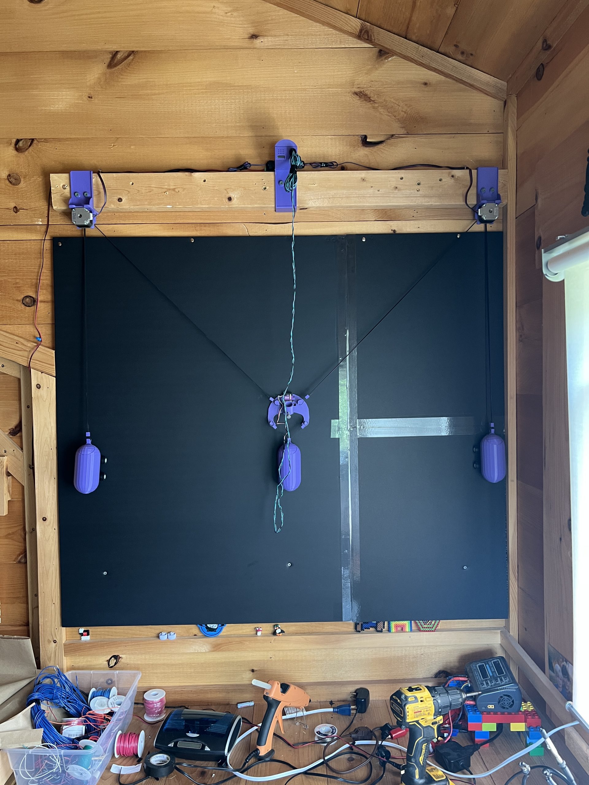
When you power on the plotter
Make sure that the gondola is positioned at the very center of the drawing surface. That’s it :).
GCode
This section is simply to convert GCode obtained from various software into Plotter Code above. The parsing is fairly rudimentary and known to work with quite a few GCode producing programs. If you run across one that doesn’t work, drop a comment. Inkscape is quirky and slow for turning an SVG into GCode, but it’s also reliable once you figured out how to do it.

Handwriting Typewriter
Not documented at the moment, I’m not sure why anyone want to use this on a Gondola Plotter, I developed it for the Tabletop version but it should work.
Mandalagaba
Connect to Mandalagaba in your browser, copy the session # and paste it in this section, click connect. The plotter will now reproduce live what is drawn in the session.

Web Instruction
Similar to the Mandalagaba section, this is meant to have the plotter take more generic instructions from an online source and reproduce them live. Give it a URL with such instructions and it’ll periodically refresh it to draw new ones as they appear.
Here’s an example of a set of instructions:
[
  {
    "id": 220,
    "pcode": "go_to( 68.888888888889, 97.777777777778 )\npen_down()\ngo_to( 67.777777777778, 90 )\ngo_to( 70, 92.222222222222 )\ngo_to( 71.111111111111, 90 )\ngo_to( 72.222222222222, 97.777777777778 )\ngo_to( 68.888888888889, 97.777777777778 )\npen_up()\n"
  },
  {
    "id": 221,
    "pcode": "go_to( 50, 73.333333333333 )\npen_down()\ngo_to( 47.777777777778, 71.111111111111 )\ngo_to( 48.888888888889, 73.333333333333 )\ngo_to( 47.222222222222, 71.111111111111 )\npen_up()\n"
  },
  {
    "id": 222,
    "pcode": "go_to( 85.555555555556, 73.333333333333 )\npen_down()\ngo_to( 84.444444444444, 74.444444444444 )\npen_up()\n"
  },
  {
    "id": 223,
    "pcode": "go_to( 95.555555555556, 85.555555555556 )\npen_down()\ngo_to( 93.333333333333, 82.222222222222 )\ngo_to( 91.111111111111, 85.555555555556 )\ngo_to( 93.333333333333, 87.777777777778 )\ngo_to( 95.555555555556, 85.555555555556 )\ngo_to( 97.777777777778, 85.555555555556 )\npen_up()\n"
  },

  ...

]
The Plotter keeps track of which IDs it has already drawn vs not, so you can keep appending to the array with new ids/instructions.
Conclusion
Congratulations on making it this far :), I hope you found the instructions helpful. All the machines I document like this one use the same software stack. This is why you’ll find references to lasers & etchers if you look under the hood. I’ve been working on drawing machines for 8 years now, it’s a little crazy how far this journey went. I have to say this Gondola Plotter is the one I put the most hours on, by a long shot. It’s just a fun machine. I wish you the same path of discovery, wow moments, and sharing with others. There is real creativity in finding weird algorithms on the internet and getting them to do something novel. It’s often found in the best corners of the internet, and it often requires patience to get them working. If you have cool ideas, please get in touch, but keep in mind that time is unfortunately finite. If you do something cool with the machine, please drop a picture, it makes my day. Have fun!
I have printed the required parts and wanted to share some quick feedback while it is still fresh. First of all, I don’t want this to sound like criticism. I’m just sharing my personal experience as a builder.
The instructions were clear: it was easy to understand what to print and in what quantity.
A small improvement would be to save the STL files in the recommended print orientation, so future builders do not have to rotate them manually before slicing.
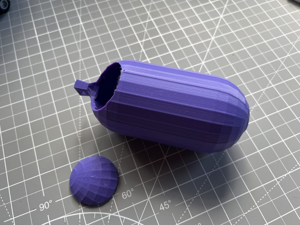
Most of my feedback is about the cylindrical weights. I think it would be useful to mention that they print well with tree supports from the build plate only. This uses less filament and avoids internal supports, which can break loose and spoil the print. That happened to me on my first attempt.
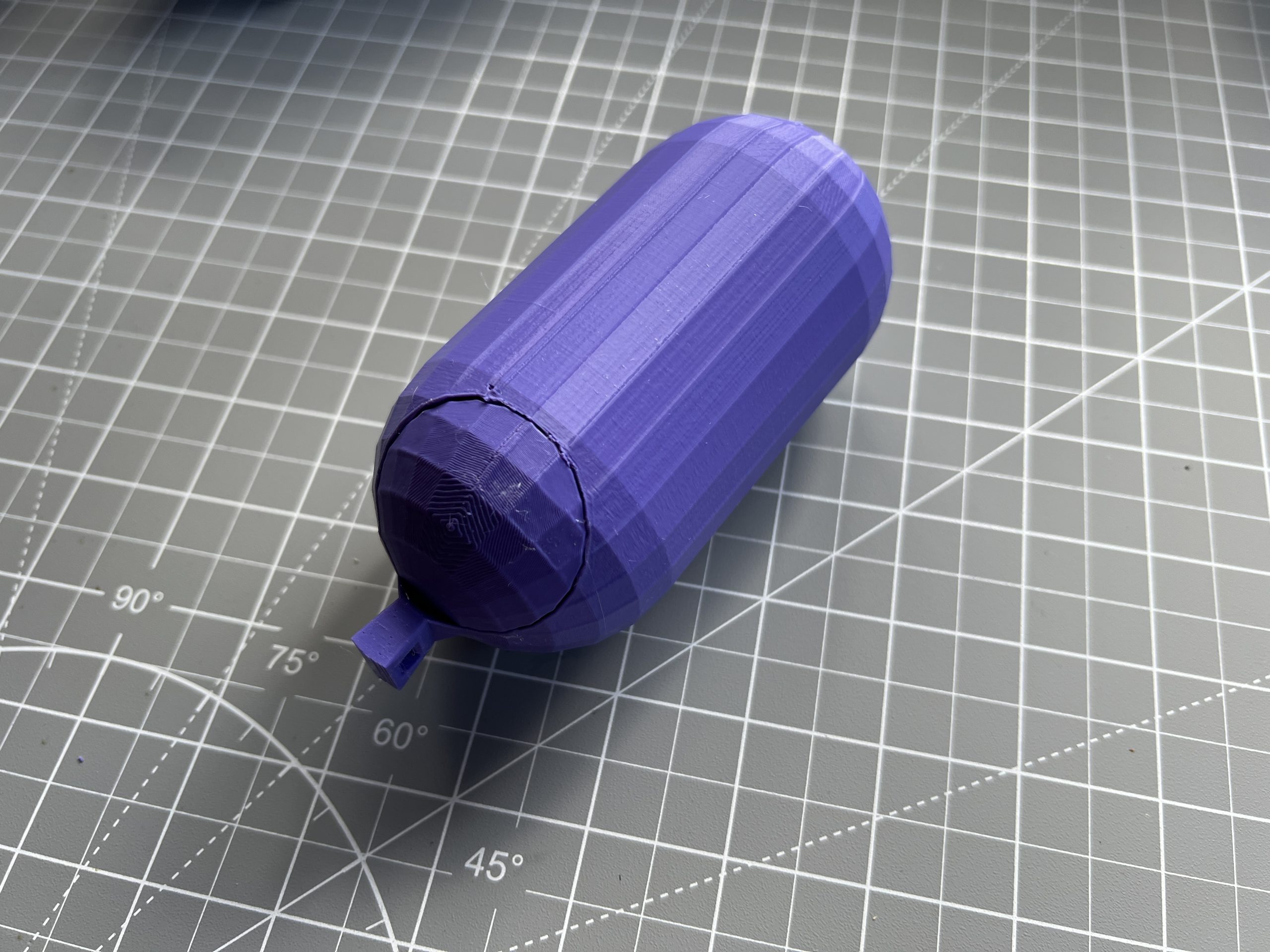
I was also a bit worried about the rounded bottom and bed adhesion, but it printed better than expected. Still, I think adding a small flat spot on the bottom would make the part easier to print and would give a cleaner outside surface. It would also probably allow the part to be printed without supports at all.
I also have some doubts about the small eyelet thickness, although since you have been using the plotter for a while, I assume it is reliable in practice.
One possible future idea: a version with a threaded cap, so there is no separate small lid that can fall out or get lost. If I have time, I may try to model this alternative.