A few things to know about the L298N
This is a rudimentary way to drive a stepper motor. You are activating the motor’s coils in sequence yourself to have it take steps. There exist cheap stepper drivers which only require 1 signal from the Pi to be instructed to execute a full step sequence.
There are 2 coils on a bipolar stepper motor, each with a + and a – side. As such, this method requires 4 pins from your Pi to drive the Motor Vs only 1 pin with a more advanced stepper driver. Equally true is that a more advanced stepper driver will require at least another pin for direction and they’ll usually have other pins for micro-stepping.
This method does not allow for micro-stepping, only full steps. This is fine enough for most applications.
Lastly, while the L298N method might appear less appealing because of the above points, I find it to be extremely robust (advanced stepper drivers can be very finicky). You can power your Pi or Arduino with it thanks to a 5V port (warning, it can only provide so many amps and a Pi running heavy processing will crash).
It can be used to drive 2 DC motors instead of 2 stepper coils of a bipolar stepper motor, and has 2 PWM pins to adjust power given to the motors. It’s a very versatile and enabling device to master. You’ll also learn a lot about how stepper motors work.
Finding your stepper motor coils
Documentation for electronics is often inaccurate, disparate, when it’s even available. It’s good to find or verify what wires you think your coils are on. To do so you can put an LED on 2 motor pins and spin it until it lights up. When it does, induction powered your LED so you know you are holding the 2 wires of a coil. The other 2 wires are obviously the other coil.
There is no good way I could find to verify which of a coil’s wire is positive or negative. In my trials, I found that it doesn’t matter for a bipolar stepper motor on an L298N. The worst that will happen is that your motor may turn in the other direction which is easy enough to fix by flipping wires.
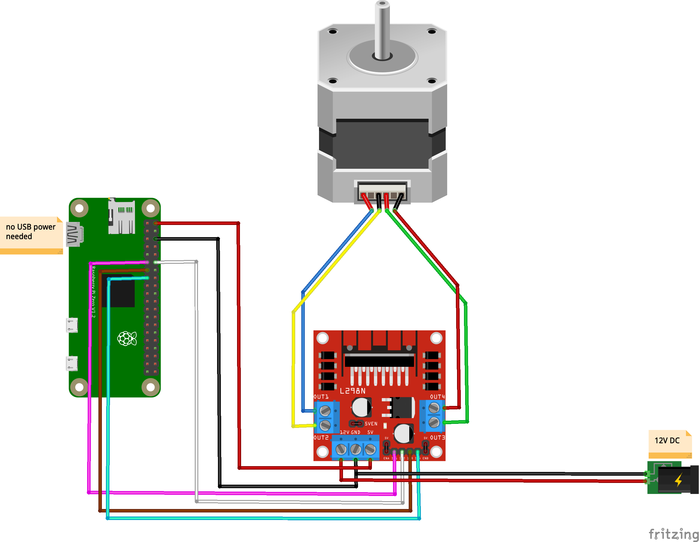
Circuit
Fritzing
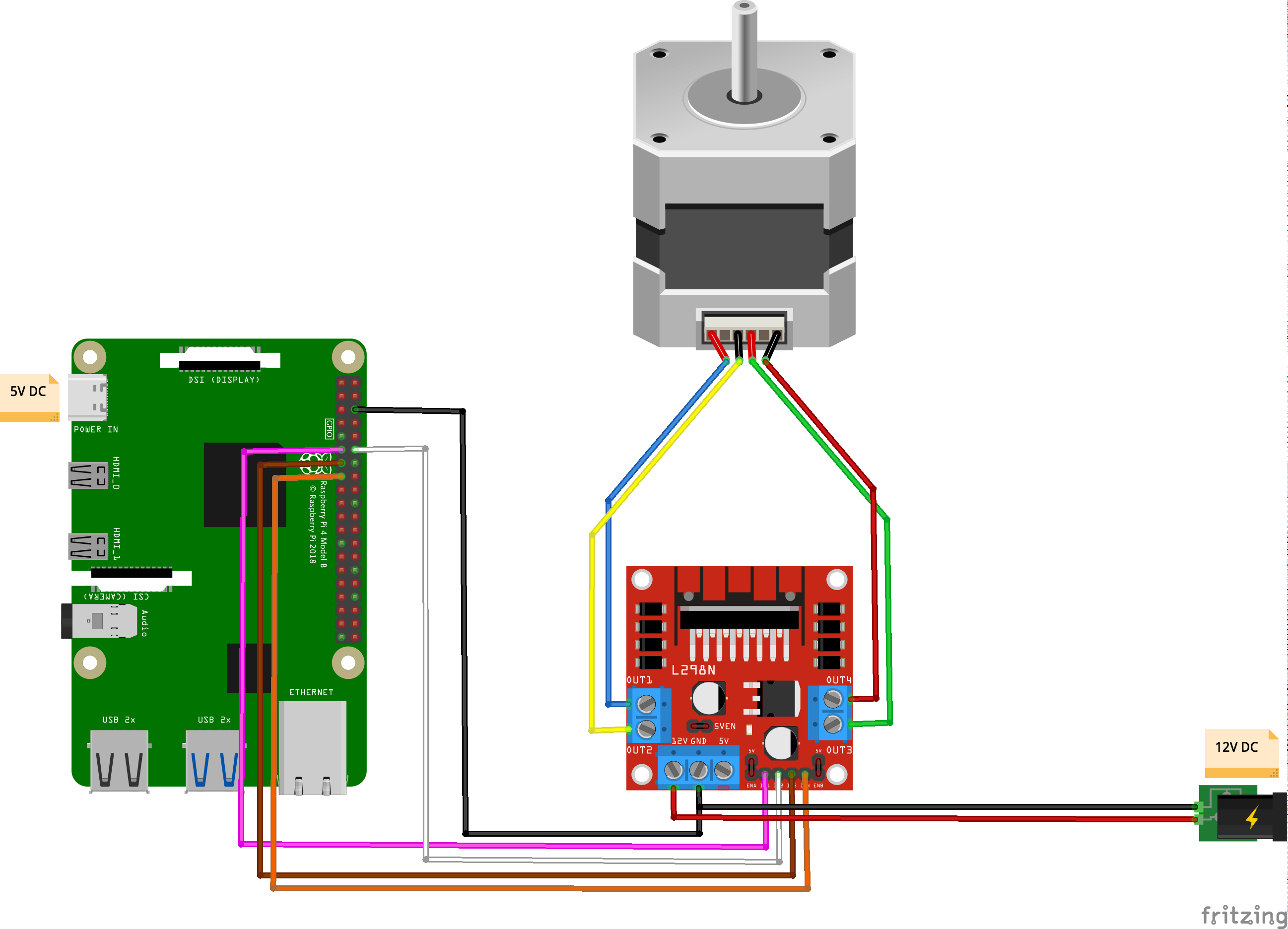
Code
[python]#!/usr/bin/python3
import RPi.GPIO as GPIO
import time
out1 = 17
out2 = 18
out3 = 27
out4 = 22
# careful lowering this, at some point you run into the mechanical limitation of how quick your motor can move
step_sleep = 0.002
step_count = 200
# setting up
GPIO.setmode( GPIO.BCM )
GPIO.setup( out1, GPIO.OUT )
GPIO.setup( out2, GPIO.OUT )
GPIO.setup( out3, GPIO.OUT )
GPIO.setup( out4, GPIO.OUT )
# initializing
GPIO.output( out1, GPIO.LOW )
GPIO.output( out2, GPIO.LOW )
GPIO.output( out3, GPIO.LOW )
GPIO.output( out4, GPIO.LOW )
def cleanup():
GPIO.output( out1, GPIO.LOW )
GPIO.output( out2, GPIO.LOW )
GPIO.output( out3, GPIO.LOW )
GPIO.output( out4, GPIO.LOW )
GPIO.cleanup()
# the meat
try:
i = 0
for i in range(step_count):
if i%4==0:
GPIO.output( out4, GPIO.HIGH )
GPIO.output( out3, GPIO.LOW )
GPIO.output( out2, GPIO.LOW )
GPIO.output( out1, GPIO.LOW )
elif i%4==1:
GPIO.output( out4, GPIO.LOW )
GPIO.output( out3, GPIO.LOW )
GPIO.output( out2, GPIO.HIGH )
GPIO.output( out1, GPIO.LOW )
elif i%4==2:
GPIO.output( out4, GPIO.LOW )
GPIO.output( out3, GPIO.HIGH )
GPIO.output( out2, GPIO.LOW )
GPIO.output( out1, GPIO.LOW )
elif i%4==3:
GPIO.output( out4, GPIO.LOW )
GPIO.output( out3, GPIO.LOW )
GPIO.output( out2, GPIO.LOW )
GPIO.output( out1, GPIO.HIGH )
time.sleep( step_sleep )
except KeyboardInterrupt:
cleanup()
exit( 1 )
cleanup()
exit( 0 )[/python]
Stuff you might need for this to run:
[bash]sudo apt-get update –fix-missing && sudo apt-get install python3-rpi.gpio[/bash]
This stepper motor is rated for rotating by 1.8° per step. This means that it takes 100 steps to rotate 180 degrees:
and 200 to do a full 360:
Power the Pi from the L298N?
As I alluded to earlier, the L298N comes with a 5V power output that is most convenient to power Pis and Arduinos as it allows you to eliminate one of the 2 power supplies to your system. Be advised that while it provides the right voltage, it does not provide enough amps to power a standard Raspberry Pi, and while it can power a Pi Zero, the later will not get enough power and crash if it works hard enough (having a camera and a live streaming server pushed it over the edge in my testing). It will power a Pi Zero on Wifi running Python which is enough for a lot of applications.
Here’s the circuit if you want to do this:
Fritzing