A much easier build than the tabletop version, but still quite a bit of work to document it all. I now have 2 or each kind :).
A much easier build than the tabletop version, but still quite a bit of work to document it all. I now have 2 or each kind :).
Awesome project! I started building it, but for some reason, the Raspberry Pi image does nothing for me. I flash it, plug the card into the Zero W, and nothing happens. The green LED flashes for a couple of seconds, then just stays solid indefinitely. Any idea what this could be? CHeers!
Hit “Send” too early 🙂 I noticed that in the instructions, there are 2 different links – the one in the “Download” section pointing to this:
http://ben.akrin.com/downloads/plottybot_2021-04-22.img
And one in the instructions for the Raspi Imager pointing here: http://ben.akrin.com/downloads/gondola_plottybot_2023-01-30.img
I tried with the first image, and that one seems to work (but probably not the right version for the vertical plotter?). Second one doesn’t seem to do anything. I also noticed that they are very different in size, first link aroun 1.7GB, second link around 400MB. Could the image in the second link be corrupt?
I think you’re the first to go through the instructions 🙂 You’re a trail blazer. Thank you for pointing out the outdated links. I just updated them with the most recent one, could you please give it another try?
Yep, now it works, thanks a lot! I have no idea why people don’t go crazy over this – this is such a great idea!! 😀
Nice! Sorry for the trouble, definitely let me know if you run into more documentation oddities. There’s no way I got it all right right off the bat, it helps others to remove all the errors. Thanks for trail blazing :).
Hi Ben,
Thanks for the instructions! I’m thinking of deploying one for myself, but am not sure what to do in terms of size.
So, could you give me some info about:
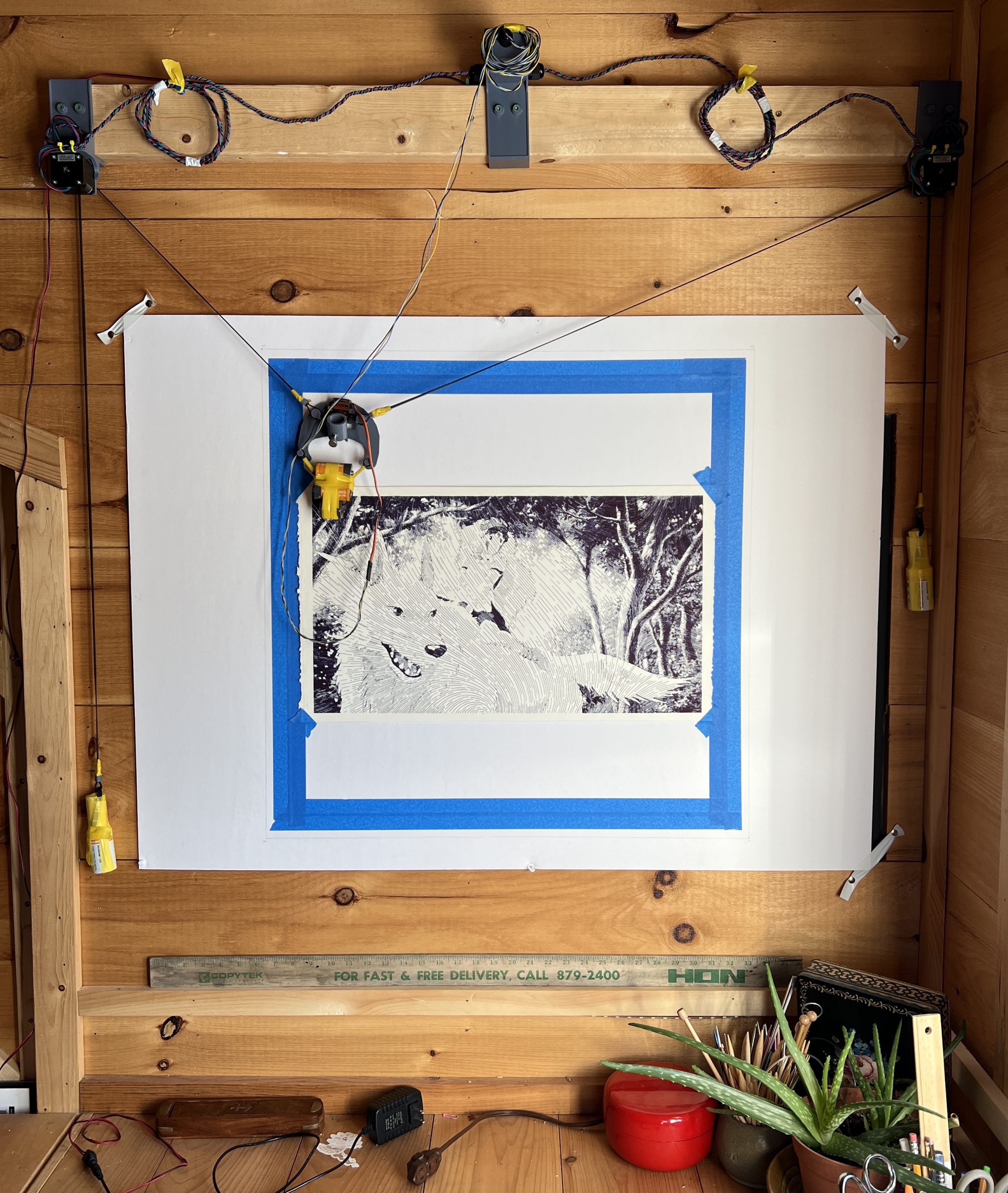
– Margins – Given the distance in your last picture, is the margin always a quarter of this distance, tying it to the plotters size?
Or is the margin always a specific width / height, which would make it independent from the plotters area?
– Accuracy – I’m thinking about making the plotter as big as I can on one wall in my office, also to use it to prepare flipcharts, etc. in advance. In order for this to work, the plotter would be roughly 2m x 2m in size, do you have any idea if the accuracy would be problematic here?
Hey Ryan,
the margins are defined as 20%, so not a fixed size. That’s what I landed on with various deployments so that’s the default, but it’s just 1 variable to adjust in the web interface. In my pictures, I think it’s set at 27% because my paper was smaller. Bottom line is you definitely want some margins on the edges, but you can play with the value, and weights on the plotter. What matters is that your belts stay straight and don’t sag. Extreme positions aren’t ideal for this hence the margin.
I don’t think you’ll have issues with accuracy at 2m, well, not from the motors at least but you’ll have to play with margins and weights. If the motors steps are too big (once again I don’t think they will be), I can help you enable microstepping.
Awesome, thanks for the info!
I’ll get to building next (which will take some time!) and get back to you afterwards 🙂
Hi Ben,
I’m in the process of building the PlottyBot now – but: What’s the WIFI password!?
1234567890 🙂 sorry it was missing in the instructions, fixing now.
Thanks!
Hi Ben,
After some back and forth with Amazon (subpar components) I was finally able to deploy my Gondola Plotty…
A couple of things I noticed – and hope I can fix with your help:
1: When booting, the left motor steadily moves to the upper left corner. I don’t think this is expected?
2: When testing, the right (bottom) motor pulls the gondola to the upper right corner – I think, that’s what I should expect.
Unfortunately, the left (bottom) motor lowers the carriage to the lower right corner. Both my motors are wired the same way, how can I fix this?!
…okay, sorry for that typo… I meant to type:
The right (bottom) […] and the left (top) […].
Hmm, seems I fixed both issues by (after powering down the PlottyBot) reversing the left motor cable…
Well, so much for that…
Now, on to reprinting everything in PETG as the PLA i initially chose is already warping due to the stepper driver’s heat…
I’m glad you figured it out, it sounded like a grounding issue or another miswiring.
Interestingly, I’ve used these drivers on PLA for hundreds or hours and didn’t experience heat issues, altough they do get toasty.
Out of curiosity, do you have a heatsink on them? Any chance you could send a picture of the warping? I’m curious to know how it affects the model.
Thank you!
Hi Ben,
I’m in the process of building the PlottyBot now – but: I can’t find the software image gondola plottyBot image.
Hi Jan,
it’s in the instructions, in the “Downloads” section: https://ben.akrin.com/gondola-plottybot/#Downloads
Sorry, I can’t read that small print on the Raspberry Pi imager screen dumps, too small, too blurry. please can you help me?
I’ve just made them so you can click on them to open them bigger. Try to reload the page and you should be able to click on them. Sorry about that.
Thank you very much but now …
Sorry, here I am again; the PlottyBot SD card image link is not working. What is the address?
No problem, it works for me:
http://ben.akrin.com/downloads/gondola_plottybot_2023-01-31.img
do you get any sort of error?
Yes, it looks like he wants to open a site but in the end nothing happens. I’ve tried this before, see Roger’s comment.
I’m not sure what to say it works for me. I can click on it and it starts to download the image file. Could you possibly try another browser? Do you have a non-standard internet connection? (satellite, cellular). Do you have a way to try from another internet connection?
Hi Ben, I found the problem; GOOGLE’s security was too high. I temporarily disabled security and then everything worked.
Thanks for the support!
Ah yeah ok, that’s not too surprising coming from them, they are over zealous with this and making sure you get ads too.
Hi Ben, I have made a test setup (and checked the connections) to check if everything works. I want to test the stepper motors and the pen movement in the Mechanics sector but nothing works. Do I have to log in somewhere or something like that?
When I report (with the test setup in operation) that I know what I am doing, I sometimes succeed in executing penup and pendown (usually not) but I cannot get the stepper motors to move.
It’s difficult to speculate on what might be going wrong with what little information you offer, and it would have been wise to not pursue the rest of the instructions when the first stepper didn’t turn. Are you soldering everything or using Dupont connectors? All I can think of here is loose connections. Did you get the exact same drivers I listed for the Stepper motors?
Hello
I built a plotter I did some tests and everything works fine, the problem started when I changed the margines, only once I managed to do it.
Many times RPi hung up turning off the power burned RPi.
Please advise how and when to change margines and what is your method of placing the drawing only on a piece of canvas for example in a corner not on the whole area
Hey Tomasz,
that’s odd I adjust the margins all the time without issue. Out of curiosity, what are you trying to set them to? I could try to do the same.
Hi
I set it once 30, change later unavailable, website does not connect to RPI,
Pi Zero 2W will be good? I wanted to buy one.
What is your method to place the drawing in one quarter, moving in Inkscape and doing g-code does not give the correct result
Tomasz, are you saying that the website became unavailable because you tried to changed the margin again? Or that it was unavailable and so you couldn’t change the margin? It sounds like your Pi is getting hung regardless of your trying to set the margins. If that’s the case you might have a loose connection somehewhere in your circuit, maybe a short. Do you have a voltmeter to verify that the Pi is getting 5V? If this is me, I’m unplugging everything from the Pi except power, I turn that on, make sure it work without getting hung, try a few operations like setting the margins, nothing will happen since everything is unplugged but that’s ok we’re just testing the Pi. Then I’m doing the same reintroducing one motor at a time.
I’m unclear on your questions about my process for sending drawings, but really it’s fairly irrelevant until you can get the machine to behave properly.
Thank you,
It could be a short circuit or a loose wire, I have 5V voltage, now RPi is broken,
I isn’t know that it could affect the execution of the program, I will be more careful and start connecting and checking as you wrote,
Do you think Pi Zero 2W will be good?
“Tomasz, are you saying that the website became unavailable because you tried to changed the margin again? Or that it was unavailable and so you couldn’t change the margin? ”
Yes, the page became unavailable after changing the margin, later I had to turn off Pi could not connect Wifi
I’m not sure if a Pi Zero 2W will work, I think it will but I haven’t tested a full build.
Hi Ben
Pi zero 2w works fine, unfortunately I still have a problem with setting margines, I did a lot of tests,
it always looks like this, after changing the margines value the page Panel or maybe raspberry does not respond, setting values undefined, the plotter panel not find any networks, waiting does not change anything only reset. I connected to Windows and Linux Mint nothing helps.
You have an idea?
Tomasz, what does happen if you just have it draw something without changing the margins? You don’t need to have a pen or even hook up the belt on the motors, just have it draw anything to see if the motors spin.
It’s so hard to believe, but it wouldn’t be the first time I ran into an IT challenge that was unbelievable :). When you set the margins, it doesn’t do anything to the electronics, it literally just changes 1 variable in software. Speaking of which, what happens if you change some of the other tunables in there? Is it just the margins that create this bizarre behavior?
Hi
Without changing the margines everything works fine, once I managed to change it to 50 but then
engines didn’t start, only the servo worked, I’ll try changing other values, maybe enter 0.3 as a percentage value
Thank you for your idea with zoom, I just solved the problem, simply pasting the margin value, ctrl+v and success, that’s the last idea I had, I’m starting to fight with g-code, I’ll definitely get back to you, Thank you
Oh ok! That gives me a clue about what it going on, but I’m still baffled about how it could result in taking down the Pi altogether. I’ll do some testing knowing this. Thank you for sticking with it and reporting this back.
Hi Ben it’s me again
can you suggest something about gcode
I have here an example of MerlinLOGO code in preview gcode,
letters are rounded, on PlottyBot they come out broken
I have this in many codes, I need arcs I have broken.
I use Inkscape
Can you see this code ? Please
%
(Header)
(Generated by gcodetools from Inkscape.)
(Using default header. To add your own header create file “header” in the output dir.)
M3
(Header end.)
G21 (All units in mm)
(Start cutting path id: polygon7833)
(Change tool to Default tool)
G00 Z5.000000
G00 X121.188134 Y53.194569
(Start cutting path id: path7829)
(Change tool to Default tool)
G00 Z5.000000
G00 X115.492950 Y36.865483
G01 Z-1.000000 F100.0(Penetrate)
G01 X115.492950 Y39.985284 Z-1.000000 F400.000000
G03 X114.712610 Y42.023056 Z-1.000000 I-3.050879 J-0.000000
G03 X113.043673 Y42.767730 Z-1.000000 I-1.668937 J-1.497845
G03 X111.335838 Y42.008909 Z-1.000000 I-0.000000 J-2.301272
G03 X110.557275 Y39.985284 Z-1.000000 I2.240601 J-2.023625
G01 X110.557275 Y36.865483 Z-1.000000
G01 X115.492950 Y36.865483 Z-1.000000
G00 Z5.000000
(End cutting path id: path7829)
(Start cutting path id: path7829)
(Change tool to Default tool)
G00 Z5.000000
G00 X119.908945 Y25.356173
G01 Z-1.000000 F100.0(Penetrate)
G01 X119.908945 Y17.893658 Z-1.000000 F400.000000
G01 X115.492627 Y17.893658 Z-1.000000
G01 X115.492627 Y34.504364 Z-1.000000
G01 X110.593750 Y34.504364 Z-1.000000
G01 X110.593750 Y17.893658 Z-1.000000
G01 X110.593750 Y12.792629 Z-1.000000
G01 X115.492627 Y12.792629 Z-1.000000
G01 X119.908945 Y12.792629 Z-1.000000
G01 X124.807499 Y12.792629 Z-1.000000
G01 X124.807499 Y17.893658 Z-1.000000
G01 X124.807499 Y25.481948 Z-1.000000
G02 X125.971810 Y28.488937 Z-1.000000 I4.465132 J-0.000000
G02 X128.518213 Y29.613815 Z-1.000000 I2.546403 J-2.319727
G02 X131.805562 Y27.293369 Z-1.000000 I0.000000 J-3.488797
G02 X132.117889 Y25.481948 Z-1.000000 I-5.096730 J-1.811421
G01 X132.117889 Y12.792629 Z-1.000000
G01 X136.018399 Y12.792629 Z-1.000000
G03 X136.526054 Y13.011384 Z-1.000000 I0.016728 J0.659604
G03 X137.017090 Y14.293126 Z-1.000000 I-1.427337 J1.281743
G01 X137.017090 Y25.356173 Z-1.000000
G03 X134.520791 Y32.243637 Z-1.000000 I-10.749650 J0.000000
G03 X128.518213 Y35.052566 Z-1.000000 I-6.002578 J-5.009182
G03 X122.447756 Y32.249895 Z-1.000000 I0.000000 J-7.975500
G03 X119.908945 Y25.356173 Z-1.000000 I8.089970 J-6.893721
G01 X119.908945 Y25.356173 Z-1.000000
G00 Z5.000000
(End cutting path id: path7829)
(Footer)
M5
G00 X0.0000 Y0.0000
M2
(Using default footer. To add your own footer create file “footer” in the output dir.)
(end)
%
That’s normal, my GCode parser does not support advanced instructions such as arc descriptions. I just translate X,Y points as I see them. The solution is that, when you save to GCode, you tell it to give you many more intermediary point. If memory serves in Inkscape they call this “Biarc interpolation tolerance”, if you make that setting lower when you save as GCode, I think that should do it.
I hope this helps.
Hi
Thank you very much for your help, changing BIARC helped, the drawings are smoothed
I watched the comments, you wrote that you can adapt your algorithm to other types of gcode
I think this algorithm works well and is interesting, but not good for PlottyBot
Maybe you could find some time to adapt it.
https://github.com/sameer/svg2gcode
It does seem to work well. I investigated every possible SVG->Gcode converter under the Sun several years ago and found them all to be lacking in some respect. Except one that I had to tweak so it could work on the enormous SVGs that I was throwing at it.
This one is new, and it seems to work quite well! I’ll do more testing with it in the future, I’m rethinking a lot of the PlottyBot stack and thinking about improvements as I’m about to port it to other devices. I was able to get it working by having it say “(Start cutting path id:)” and “(End cutting path id:)” around the pen strokes, it lets you do that in the settings (even though it has issues doing so exactly how I want it). But it did work and I was able to stick the GCode in the PlottyBot web interface and have it render.
Ultimately all my GCode parsing does is look for (Start cutting path id:) & (End cutting path id:). I will generalize this when I revisit this part of the stack :).
Great find!